Table of Contents
Advertisement
Quick Links
Module for Stepper
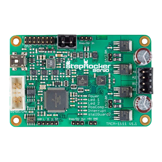
TMCM-1111 StepRocker Hardware Manual
Hardware Version V1.10 | Document Revision V1.02 • 2021-MAR-26
The TMCM-1111 StepRocker is a single axis motor controller/driver board for 2-phase bipolar step-
per motors. It supports S-shaped ramps in addition to linear ramps and closed-loop operation
together with an external encoder.
Applications
• Laboratory Automation
• Manufacturing
• Robotics
Simpli ed Block Diagram
©2021 TRINAMIC Motion Control GmbH & Co. KG, Hamburg, Germany
Terms of delivery and rights to technical change reserved.
Download newest version at:
www.trinamic.com
Read entire documentation.
• Factory Automation
• Test & Measurement
• Technology evaluation
Features
• Single axis controller/driver for 2-phase
bipolar stepper motor
• S-shaped ramps
linear ramps
• Closed-loop operation with external
encoder
• +10. . . 30V DC supply voltage
• Up to 2.8A RMS motor current
• RS485 & USB interface
• multi-purpose inputs and outputs
• First experiences with stepper
motors
• Hobby applications
MODULE
Advertisement
Table of Contents

Related Manuals for Trinamic StepRocker TMCM-1111


Summary of Contents for Trinamic StepRocker TMCM-1111
- Page 1 • Test & Measurement • Robotics • Technology evaluation • Hobby applications Simpli ed Block Diagram ©2021 TRINAMIC Motion Control GmbH & Co. KG, Hamburg, Germany Terms of delivery and rights to technical change reserved. Download newest version at: www.trinamic.com Read entire documentation.
-
Page 2: Table Of Contents
..........26 ©2021 TRINAMIC Motion Control GmbH & Co. KG, Hamburg, Germany Terms of delivery and rights to technical change reserved. -
Page 3: Features
• TMCL™ remote (direct mode) and standalone operation (memory for up to 1024 TMCL™ commands) • Fully supported by TMCL-IDE (PC based integrated development environment) ©2021 TRINAMIC Motion Control GmbH & Co. KG, Hamburg, Germany Terms of delivery and rights to technical change reserved. -
Page 4: Order Codes
RS485 and USB interfaces Table 1: TMCM-1111 StepRocker Order Code ©2021 TRINAMIC Motion Control GmbH & Co. KG, Hamburg, Germany Terms of delivery and rights to technical change reserved. Download newest version at www.trinamic.com... -
Page 5: Mechanical And Electrical Interfacing
4 x M3 screws Figure 1: Board Dimensions and Position of Mounting Holes (all Values in mm) ©2021 TRINAMIC Motion Control GmbH & Co. KG, Hamburg, Germany Terms of delivery and rights to technical change reserved. Download newest version at... -
Page 6: Connectors
Low pro le IDC socket connector, 10 ing bar, type 8380, 10 pin, DIN 41651, pin, DIN 41651, 2.54mm pitch 2.54mm pitch ©2021 TRINAMIC Motion Control GmbH & Co. KG, Hamburg, Germany Terms of delivery and rights to technical change reserved. Download newest version at www.trinamic.com... - Page 7 Two-pin-connector, 2.54mm pitch Female connector with 2.54mm pitch Table 2: Connector Types and Mating Connectors of the TMCM-1111 StepRocker ©2021 TRINAMIC Motion Control GmbH & Co. KG, Hamburg, Germany Terms of delivery and rights to technical change reserved. Download newest version at...
-
Page 8: Power Connector
0. . . +10V, resolution: 12bit (0. . . 4095) PHASE_A Encoder input channel A (+5V compatible, internal pull-up to +5V) ©2021 TRINAMIC Motion Control GmbH & Co. KG, Hamburg, Germany Terms of delivery and rights to technical change reserved. Download newest version at www.trinamic.com... -
Page 9: Motor Connector
Input for left limit switch (STOP_L) Input for right limit switch (STOP_R) Input for home switch (HOME) ©2021 TRINAMIC Motion Control GmbH & Co. KG, Hamburg, Germany Terms of delivery and rights to technical change reserved. Download newest version at... -
Page 10: Rs485 And Can Connector
It is not necessary to remove SN65HVD1050D 0.1µF capacitor the RS485 transceiver. Housing: SOIC8 Housing: 0603 ©2021 TRINAMIC Motion Control GmbH & Co. KG, Hamburg, Germany Terms of delivery and rights to technical change reserved. Download newest version at www.trinamic.com... -
Page 11: Usb Connector
Dir Out Motion controller direction output signal (+5V compati- ble) Table 10: Step/Dir Output Connector Pin Assignment ©2021 TRINAMIC Motion Control GmbH & Co. KG, Hamburg, Germany Terms of delivery and rights to technical change reserved. Download newest version at www.trinamic.com... -
Page 12: Output Connector
Table 12: Programming Pads on Bottom of PCB +3V3 SWDCLK SWDIO nRST Figure 3: TMCM-1111 StepRocker Programming Pads ©2021 TRINAMIC Motion Control GmbH & Co. KG, Hamburg, Germany Terms of delivery and rights to technical change reserved. Download newest version at www.trinamic.com... -
Page 13: Reset To Factory Default
7. Switch the supply power on and wait until LED1 ashes normally again. The TMCM-1111 StepRocker now runs with factory default settings. ©2021 TRINAMIC Motion Control GmbH & Co. KG, Hamburg, Germany Terms of delivery and rights to technical change reserved. -
Page 14: Jumper Settings
Jumper plugged: motor current up to 2.8A RMS Jumper unplugged: motor current up to 1A RMS Table 13: Jumpers of the TMCM-1111 StepRocker ©2021 TRINAMIC Motion Control GmbH & Co. KG, Hamburg, Germany Terms of delivery and rights to technical change reserved. Download newest version at... -
Page 15: Leds
The LED is connected to the SG_TST pin of the TMC262. Table 14: LED Description Figure 5: TMCM-1111 StepRocker LEDs ©2021 TRINAMIC Motion Control GmbH & Co. KG, Hamburg, Germany Terms of delivery and rights to technical change reserved. Download newest version at www.trinamic.com... -
Page 16: Communication
Certain RS485 interface converters available for PCs already include these additional resistors (e.g. USB-2-485). ©2021 TRINAMIC Motion Control GmbH & Co. KG, Hamburg, Germany Terms of delivery and rights to technical change reserved. Download newest version at... -
Page 17: Usb
(120 Ohm) keep distance as short as possible Figure 8: CAN bus structure with termination resistors ©2021 TRINAMIC Motion Control GmbH & Co. KG, Hamburg, Germany Terms of delivery and rights to technical change reserved. Download newest version at www.trinamic.com... - Page 18 Therefore, 120 Ohm termination resistors at both ends of the bus have to be added externally. ©2021 TRINAMIC Motion Control GmbH & Co. KG, Hamburg, Germany Terms of delivery and rights to technical change reserved. Download newest version at...
-
Page 19: Functional Description
TMCL™ high level commands like move to position a rapid and fast development of motion control applications is guaranteed. Whereas the boot loader is installed during production and testing at TRINAMIC and remains usually untouched throughout the whole lifetime, the rmware can be updated by the user. -
Page 20: Operational Ratings And Characteristics
Number of nodes connected to single RS485 network RS485 Table 16: Operational ratings of the RS485 interface ©2021 TRINAMIC Motion Control GmbH & Co. KG, Hamburg, Germany Terms of delivery and rights to technical change reserved. Download newest version at... -
Page 21: Abbreviations Used In This Manual
Root Mean Square value TMCL TRINAMIC Motion Control Language Table 17: Abbreviations used in this Manual ©2021 TRINAMIC Motion Control GmbH & Co. KG, Hamburg, Germany Terms of delivery and rights to technical change reserved. Download newest version at www.trinamic.com... -
Page 22: Figures Index
....TMCM-1111 StepRocker block diagram ©2021 TRINAMIC Motion Control GmbH & Co. KG, Hamburg, Germany Terms of delivery and rights to technical change reserved. Download newest version at... -
Page 23: Tables Index
....Document Revision ... ©2021 TRINAMIC Motion Control GmbH & Co. KG, Hamburg, Germany Terms of delivery and rights to technical change reserved. Download newest version at... -
Page 24: Supplemental Directives
14.5 Disclaimer: Life Support Systems TRINAMIC Motion Control GmbH & Co. KG does not authorize or warrant any of its products for use in life support systems, without the speci c written consent of TRINAMIC Motion Control GmbH & Co. KG. -
Page 25: Collateral Documents & Tools
In particular, this also applies to the stated possible applications or areas of applications of the product. TRINAMIC products are not designed for and must not be used in connection with any applications where the failure of such products would reasonably be expected to result in signi cant personal injury or death (safety-Critical Applications) without TRINAMIC’s speci c written consent. -
Page 26: Revision History
New product picture on rst page. 1.02 2021-MAR-26 Added reset to factory default. Table 19: Document Revision ©2021 TRINAMIC Motion Control GmbH & Co. KG, Hamburg, Germany Terms of delivery and rights to technical change reserved. Download newest version at www.trinamic.com...
Need help?
Do you have a question about the StepRocker TMCM-1111 and is the answer not in the manual?
Questions and answers