Table of Contents
Advertisement
Quick Links
MECHATRONIC DRIVE WITH STEPPER MOTOR
Hardware Version V1.4
HARDWARE MANUAL
+
+
U
F
:
NIQUE
EATURES
TRINAMIC Motion Control GmbH & Co. KG
Hamburg, Germany
www.trinamic.com
PD28-1-1021
+
PD28-3-1021
Stepper Motor NEMA11 / 28mm
0.06 - 0.12Nm
with Controller / Driver
up-to 0.7A RMS / 24V DC
sensOstep™ Encoder
RS485 Interface
+
PANdrive
Advertisement
Table of Contents

Related Manuals for Trinamic PD28-1-1021


Summary of Contents for Trinamic PD28-1-1021
- Page 1 Hardware Version V1.4 HARDWARE MANUAL PD28-1-1021 PD28-3-1021 Stepper Motor NEMA11 / 28mm 0.06 - 0.12Nm with Controller / Driver up-to 0.7A RMS / 24V DC sensOstep™ Encoder RS485 Interface NIQUE EATURES TRINAMIC Motion Control GmbH & Co. KG Hamburg, Germany www.trinamic.com...
-
Page 2: Table Of Contents
PD28-1-1021 / PD28-3-1021 V1.4 Hardware Manual (Rev. 1.03 / 2018-JAN-25) Table of Contents Features ................................... 3 Order Codes ................................... 5 Mechanical and Electrical Interfacing ........................6 3.1.1 Dimensions of PD28-1-1021 ........................6 3.1.2 Dimensions of PD28-3-1021 ........................7 Motor Characteristics ............................8 Integrated sensOstep™... -
Page 3: Features
PD28-1-1021 / PD28-3-1021 V1.4 Hardware Manual (Rev. 1.03 / 2018-JAN-25) Features The PANdrive™ PD28-1-1021 and PD28-3-1021 are small and compact full mechatronic solutions including NEMA11 / 28mm flange size stepper motors, the TMCM-1021 controller/ driver electronics and TRINAMIC sensOstep™ encoder for step-loss detection. The two PANdrives include stepper motor with different lengths and different holding torques (PD28-1-1021: 0.06Nm, PD28-3-1021: 0.12Nm) but, same electronics... - Page 4 PD28-1-1021 / PD28-3-1021 V1.4 Hardware Manual (Rev. 1.03 / 2018-JAN-25) TRINAMIC – E TMCL NIQUE EATURES ASY TO SE WITH stallGuard2™ stallGuard2 is a high-precision sensorless load measurement using the back EMF on the coils. It can be used for stall detection as well as other uses at loads below those which stall the motor.
-
Page 5: Order Codes
PD28-1-1021 / PD28-3-1021 V1.4 Hardware Manual (Rev. 1.03 / 2018-JAN-25) Order Codes The combination of motor and motor mounted controller/driver electronic is currently available with two stepper motors (different length and holding torque). The length of the PANdrives™ is specified without the length of the axis. For the overall length of the product please add 21 mm (see detailed drawings in chapter 3). -
Page 6: Mechanical And Electrical Interfacing
PD28-1-1021 / PD28-3-1021 V1.4 Hardware Manual (Rev. 1.03 / 2018-JAN-25) Mechanical and Electrical Interfacing The PD28-1-1021 consists of the NEMA11 / 28mm flange size stepper motor QSH2818-32-07-006 with controller / driver electronics TMCM-1021 mounted on its backside and integrated sensOstep™ encoder. The PD28-3-1021 uses the longer QSH2818-51-07-012 NEMA11 / 28mm stepper motor together with the same electronics and encoder. -
Page 7: Dimensions Of Pd28-3-1021
PD28-1-1021 / PD28-3-1021 V1.4 Hardware Manual (Rev. 1.03 / 2018-JAN-25) 3.1.2 Dimensions of PD28-3-1021 The PD28-3-1021 consists of the stepper motor QSH2818-51-07-012, the TMCM-1021 controller / driver electronics and integrated sensOstep™ encoder. Figure 3.2 PD28-3-1021 dimensions (all dimensions in mm) -
Page 8: Motor Characteristics
PD28-1-1021 / PD28-3-1021 V1.4 Hardware Manual (Rev. 1.03 / 2018-JAN-25) 3.2 Motor Characteristics Main characteristics of the two different motors available as part of the PD28-1-1021 (QSH2818-32-07-006) and PD28-3-1021 (QSH2818-51-07-012): Paramete Specification Units QSH2818-32-07-006 QSH2818-51-07-012 Related PANdrive PD28-1-1021 PD28-3-1021 Rated Voltage... -
Page 9: Integrated Sensostep™ Encoder
PD28-1-1021 / PD28-3-1021 V1.4 Hardware Manual (Rev. 1.03 / 2018-JAN-25) 3.3 Integrated sensOstep™ encoder The PD28-1-1021 and PD28-3-1021 PANdrive offer integrated sensOstep™ encoders based on hall sensor technology. As the name “sensOstep™” already indicates intended use of this type of compact and highly integrated encoder is step loss detection of motor movements. -
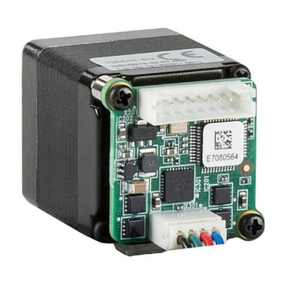
Page 10: Connectors
PD28-1-1021 / PD28-3-1021 V1.4 Hardware Manual (Rev. 1.03 / 2018-JAN-25) 3.4 Connectors The PD-1021 has two connectors, an 8-pin power and input/output connector and a 4-pin motor connector (used to connect the attached motor). Power / communication / I/Os Motor Figure 3.3 PD-1021 connectors... -
Page 11: Power, Communication And I/O Connector
For proper operation care has to be taken with regard to power supply concept and design. Due to space restrictions the PD28-1-1021 / PD28-3-1021 includes just about 20µF/35V (TMCM-1021 V1.2) resp. 30µF/35V (TMCM-1021 V1.4) of supply filter capacitors. These are ceramic capacitors which have been selected for high reliability and long life time. - Page 12 3.4.1.2 RS485 For remote control and communication with a host system the PD28-1-1021 / PD28-3-1021 provides a two wire RS485 bus interface. For proper operation the following items should be taken into account when setting up an RS485 network: BUS STRUCTURE: The network topology should follow a bus structure as closely as possible.
- Page 13 3.4.1.3 Digital Inputs IN_0 and IN_1 The eight pin connector of the PD28-1-1021 / PD28-3-1021 provides four general purpose inputs IN_0, IN_1, IN_2 and IN_3. The first two inputs have dedicated connector pins while the other two share pins with two general purpose outputs.
- Page 14 3.4.1.4 Inputs IN_2, IN_3, Digital Outputs OUT_0, OUT_1 The eight pin connector of the PD28-1-1021 / PD28-3-1021 provides two general purpose outputs. These two outputs are open-drain outputs and can sink up to 100mA each. Both outputs OUT_0 and OUT_1 share pins with two of the four inputs (IN_2 resp.
- Page 15 PD28-1-1021 / PD28-3-1021 V1.4 Hardware Manual (Rev. 1.03 / 2018-JAN-25) The inputs are protected using voltage resistor dividers together with limiting diodes against voltages below 0V (GND) and above +3.3V DC. The circuit of the two outputs and the two inputs connected in...
- Page 16 PD28-1-1021 / PD28-3-1021 V1.4 Hardware Manual (Rev. 1.03 / 2018-JAN-25) For hardware version 1.2: Do not connect either IN_2 or IN_3 directly to a low resistance supply voltage (e.g. directly to any power supply voltage). As the output transistors connected in parallel might briefly switch-on during power-up they might be damaged / destroyed if the current through the transistors to ground exceeds 100mA.
-
Page 17: Motor Connector
Therefore, make sure the motor current is properly set. Also with hardware version 1.4 the low current range is set as default. Do not use the high current range with the PD28-1-1021 and PD28-3-1021 PANdrives for prolonged time! -
Page 18: Motor Driver Current
TMCM-1021 hardware revision V1.4, only – not with hardware revision V1.2! Be careful when setting motor current! The stepper motors used for the PD28-1-1021 and PD28-3-1021 PANdrives have a rated current of 0.67A RMS. Therefore, it is not recommended to use any current setting significantly above the rated motor current –... - Page 19 PD28-1-1021 / PD28-3-1021 V1.4 Hardware Manual (Rev. 1.03 / 2018-JAN-25) Motor current Range setting Current Motor Motor setting in in software scaling step current current software (TMCL) (TMCL) (CS) COIL_PEAK COIL_RMS 80..87 0.378 0.267 88..95 0.413 0.292 96..103 0.447 0.316 104..111...
- Page 20 248..255 2.033 1.438 Please note: these settings clearly exceed motor current rating for the PD28-1-1021 and PD28-3-1021 configurations! In addition to the settings in the table the motor current may be switched off completely (free-wheeling) using axis parameter 204 (see TMCM-1021 firmware manual).
-
Page 21: Reset To Factory Defaults
PD28-1-1021 / PD28-3-1021 V1.4 Hardware Manual (Rev. 1.03 / 2018-JAN-25) Reset to Factory Defaults It is possible to reset the PD28-1-1021 / PD28-3-1021 to factory default settings without establishing a communication link. This might be helpful in case communication parameters of the preferred interface have been set to unknown values or got accidentally lost. -
Page 22: Operational Ratings
*) High current range available as new additional range with TMCM-1021 hardware revision V1.4 – not with hardware revision V1.2. High current range settings not recommended for PANdrives PD28-1-1021 and PD28- 3-1021 as the higher current settings will significantly exceed rated motor current of 0.67A RMS. - Page 23 PD28-1-1021 / PD28-3-1021 V1.4 Hardware Manual (Rev. 1.03 / 2018-JAN-25) Symbol Parameter Unit Number of nodes connected to single RS485 RS485 network Maximum bit rate supported on RS485 connection 9600 115200 bit/s RS485 Table 7.3 Operational ratings of RS485 interface...
-
Page 24: Torque Curves
0,07 0,06 0,05 0,04 0,03 0,02 0,01 0,00 1000 10000 speed[rpm] Figure 8.1 PD28-1-1021 torque vs. speed 24V / 0.7 A, 256 µsteps PD28-3-1021 - 0.7A RMS Phase Current, 256 uSteps 0,20 0,18 0,16 0,14 0,12 0,10 0,08 0,06 0,04... -
Page 25: Functional Description
PD28-1-1021 / PD28-3-1021 V1.4 Hardware Manual (Rev. 1.03 / 2018-JAN-25) Functional description The PD28-1-1021 and PD28-3-1021 are highly integrated mechatronic devices which can be controlled via RS485 serial interface. Communication traffic is kept low since all time critical operations, e.g. ramp calculations are performed on board. -
Page 26: Life Support Policy
PD28-1-1021 / PD28-3-1021 V1.4 Hardware Manual (Rev. 1.03 / 2018-JAN-25) 10 Life Support Policy TRINAMIC Motion Control GmbH & Co. KG does not authorize or warrant any of its products for use in life support systems, without the specific written consent of TRINAMIC Motion Control GmbH &... -
Page 27: Revision History
Figure 11.1: Document revision 11.2 Hardware Revision Please note: all current PD28-1-1021 and PD28-3-1021 PANdrives use controller driver electronics TMCM-1021 V1.4. Previous versions used TMCM-1021 V1.2. All other TMCM-1021 hardware versions listed below have been used for prototypes, only. The following list includes changes in hardware for the TMCM-1021 controller / driver electronics since initial hardware (prototype) version V1.0:... -
Page 28: References
PD28-1-1021 / PD28-3-1021 V1.4 Hardware Manual (Rev. 1.03 / 2018-JAN-25) Version Date Description / Modifications compared to previous versions extended current settings the module supports NEMA11 (28mm) bipolar stepper motors using the lower current range and also NEMA17 (42mm) bipolar stepper motors using the higher current range –... - Page 29 Mouser Electronics Authorized Distributor Click to View Pricing, Inventory, Delivery & Lifecycle Information: Trinamic PD28-3-1021-TMCL PD28-1-1021-TMCL PD-1021-CABLE...
Need help?
Do you have a question about the PD28-1-1021 and is the answer not in the manual?
Questions and answers