Table of Contents
Advertisement
Quick Links
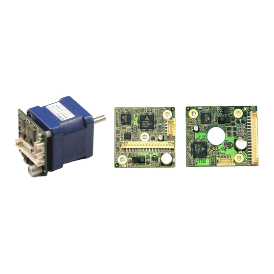
PANdrive PD013-42
and
TMCM-013 and TMCM-013-LA
Manual
STEPPER motor controller/driver module
1A RMS (1.5A peak) / 30V
with RS485 and step-/ direction interface
Trinamic Motion Control GmbH & Co. KG
Sternstraße 67
D – 20357 Hamburg, Germany
Phone +49-40-51 48 06 – 0
FAX: +49-40-51 48 06 – 60
http://www.trinamic.com
INFO@TRINAMIC.COM
Advertisement
Table of Contents

Related Manuals for Trinamic PANdrive PD013-42


Summary of Contents for Trinamic PANdrive PD013-42
- Page 1 Manual STEPPER motor controller/driver module 1A RMS (1.5A peak) / 30V with RS485 and step-/ direction interface Trinamic Motion Control GmbH & Co. KG Sternstraße 67 D – 20357 Hamburg, Germany Phone +49-40-51 48 06 – 0 FAX: +49-40-51 48 06 – 60 http://www.trinamic.com...
-
Page 2: Table Of Contents
Changes required for DC motor mode operation............... 23 6.5.2 Parameterizing with RS485 ....................24 6.5.3 Motion Control........................24 Revision History ..........................25 Documentation Revision ......................25 Firmware Revision ........................25 References ............................. 26 Copyright © 2005, TRINAMIC Motion Control GmbH & Co. KG... - Page 3 Table 6.6: Baud rate ..........................18 Table 6.7: Adjusting of Microstep Resolution ..................19 Table 6.8: External signals and motor reactions ................... 21 Table 7.1: Documentation Revisions..................... 25 Table 7.2: Firmware Revisions......................25 Copyright © 2005, TRINAMIC Motion Control GmbH & Co. KG...
-
Page 4: Features
59 x 42 x 42 PD3-013-42 PANdrive 0.49Nm 69 x 42 x 42 TMCM-013 Electronics module 14 x 42 x 42 TMCM-013-LA Electronics module 14 x 42 x 50 Table 1.1: Order codes Copyright © 2005, TRINAMIC Motion Control GmbH & Co. KG... -
Page 5: Life Support Policy
Specifications subject to change without notice. Copyright © 2005, TRINAMIC Motion Control GmbH & Co. KG... -
Page 6: Outer Description
RS485 remote control access A, TTL input RS485B RS485 remote control access B, TTL input OA1, OA2 Connections for motor coil A OB1, OB2 Connections for motor coil B Table 3.1: Pinning of TMCM-013 and TMCM-013-LA Copyright © 2005, TRINAMIC Motion Control GmbH & Co. KG... -
Page 7: Dimensions
12.5mm 5.4 mm 44.6 mm 50.0 mm Figure 3.3: Dimensions for TMCM-013LA 3.3 Connectors Both connectors are crimp connectors series B4B-PH-SM3-TB, PH-connector. Motor: 4 pin connector Control: 16 pin connector Copyright © 2005, TRINAMIC Motion Control GmbH & Co. KG... -
Page 8: Operational Ratings
DELAY Impulse active (falling) edge set up time before step Impulse µs SETUP Analog input voltage on GPI 0 .. 28 Environment temperature for °C operation Table 4.1: Operational Ratings Copyright © 2005, TRINAMIC Motion Control GmbH & Co. KG... -
Page 9: Step, Direction And Disable Inputs
E: Emitter Step Figure 4.1: Step, Direction and Disable Inputs Examples: = 5V undefined OPTON OPTOFF = 0V 1.5V 4.0V STEP = 20V undefined OPTON OPTOFF = 0V 16.5V 19.0V STEP Copyright © 2005, TRINAMIC Motion Control GmbH & Co. KG... -
Page 10: Getting Started
100% of nominal motor current (see motor data sheet). Mode 2 and mode 1 are mainly intended for slow, smooth and very exact movements, due to the high microstepping resolution. For dynamic operation choose mode 0. Copyright © 2005, TRINAMIC Motion Control GmbH & Co. KG... -
Page 11: Chopper Modes 0 (Spi / Default Mode) And 1 (Pwm)
12 V 466 mH 2300 mH 24 V 1720 mH 18 V 350 mA 1150 mH 12 V 666 mH Table 5.1: Maximum Supply Voltage regarding Motor Current and Inductivity Copyright © 2005, TRINAMIC Motion Control GmbH & Co. KG... -
Page 12: Figure 5.2: Maximum Supply Voltage Regarding Motor Current And Inductivity
Any combination of motor coil current and inductivity witch is above the curve for maximum supply voltage (V ) is possible to drive the motor in this mode. Check your motor statistics, please. Copyright © 2005, TRINAMIC Motion Control GmbH & Co. KG... -
Page 13: Motor Contact
Pin 4 Pin 3 Common Step Pin 2 Step Pin 1 Velocity Deceleration Acceleration const. PWR 7...28 V Figure 5.4: Contacts for Step-Direction The maximum step frequency is 350 kHz. Copyright © 2005, TRINAMIC Motion Control GmbH & Co. KG... -
Page 14: Connections For Rs485-Mode
Pin 14 Other direction: AV -50000 Current: AC 50 Acceleration: AA 400 Stop: AV 0 optional RS 485 Interface Pin 2 Pin 1 PWR 7...28 V Figure 5.5: Contacts for RS485 Copyright © 2005, TRINAMIC Motion Control GmbH & Co. KG... -
Page 15: Functional Description
EEPROM to obtain the changes after a restart. A Reset to factory default is possible. Default address byte is “A” and default baud rate is 9600 baud. Copyright © 2005, TRINAMIC Motion Control GmbH & Co. KG... -
Page 16: Rs485 Commands
1. S Select SPI Mode: AM 0 ⇒ ENTER 2. Read out the actual mode Am ⇒ ENTER ⇒ CR (carriage return) 3. Change Microstep resolution ¼ of max. resolution AZ 2 ⇒ ENTER Copyright © 2005, TRINAMIC Motion Control GmbH & Co. KG... -
Page 17: Example For Test Move
Motor stops when StallGuard value is reached and position is set zero -7..-1 (useful for reference run). StallGuard function is deactivated (default) 1..7 Motor stops when StallGuard value is reached and position is not set zero. Table 6.3: StallGuard Copyright © 2005, TRINAMIC Motion Control GmbH & Co. KG... -
Page 18: Limit Switch (L)
The parameter ‘U’ changes the baud rate of the module for RS485 communication. Parameter U Baud rate 9600 baud 14400 baud 19200 baud 28800 baud 38400 baud 57600 baud 76800 baud 115200 baud Table 6.6: Baud rate Copyright © 2005, TRINAMIC Motion Control GmbH & Co. KG... -
Page 19: Store Parameters To Eeprom (W)
The minimum supply voltage has to be above two times the nominal motor voltage. ⋅ ≤ ≤ ⋅ ⋅ COIL MOTOR It uses a chopper frequency of about 36kHz. Copyright © 2005, TRINAMIC Motion Control GmbH & Co. KG... -
Page 20: Chopper Mode 1 (Pwm)
If x is in the range 0.5 to 1.0, try operating your motor and check if motor or driver gets too hot. If x is above 1.0, choose one of the other chopper modes. See also chapter 5.2.1.2 for graphical demonstration. Copyright © 2005, TRINAMIC Motion Control GmbH & Co. KG... -
Page 21: Step-Direction
6.3.1 Direction Description: The Direction signal changes the motors rotation from clockwise (CW) to counterclockwise (CCW) and vice versa. Function Table: open wire = 5…24V motor CW motor CCW turn Copyright © 2005, TRINAMIC Motion Control GmbH & Co. KG... -
Page 22: Step
3 of the free contacts for a 6-pin connector on the backside of the module. See Figure 6.3. Turn on the module and switch it off again to remove the short-circuit. All settings are now at factory default. pin 1 pin 3 Figure 6.3: Reset to factory default Copyright © 2005, TRINAMIC Motion Control GmbH & Co. KG... -
Page 23: Option: Pseudo Dc-Motor Mode
R = 3,3k ATMEGA168 Figure 6.4: Layout Changes for act like DC-Motor option R = 100k R = 3.3k TMCM-013LA TMCM-013 TMCM-013-LA Keep in mind: This Changes can be made externally also. Copyright © 2005, TRINAMIC Motion Control GmbH & Co. KG... -
Page 24: Parameterizing With Rs485
Change the voltage at GPI between 7…28V. The motor will accelerate and decelerate relative to the specified zero point. Additional parameters like resolutions of microsteps can be stored in the EEPROM. Copyright © 2005, TRINAMIC Motion Control GmbH & Co. KG... -
Page 25: Revision History
(LED) now command ‘O’. Switched default mode to SPI. Table 7.1: Documentation Revisions 7.2 Firmware Revision Version Comment Description 1.05 First Release Full functionality (except DC-Motor) with some possibilities to expand Table 7.2: Firmware Revisions Copyright © 2005, TRINAMIC Motion Control GmbH & Co. KG... -
Page 26: References
TMCM-013 Manual (V1.14 / January 17th, 2006) 8 References Copyright © 2005, TRINAMIC Motion Control GmbH & Co. KG...
Need help?
Do you have a question about the PANdrive PD013-42 and is the answer not in the manual?
Questions and answers