Table of Contents
Advertisement
Quick Links
Module for Stepper
TMCM-3230 Hardware Manual
Hardware Version V1.30 | Document Revision V1.20 • 2019-MAR-01
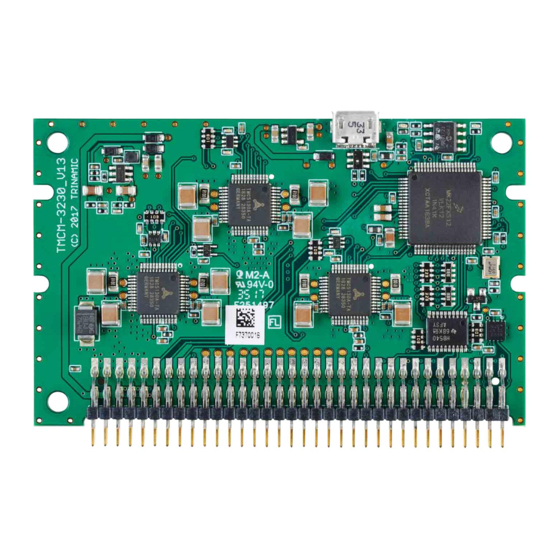
The TMCM-3230 is a compact and easy to use 3-axes stepper motor controller and driver unit for
embedded applications. It offers CAN bus, UART and USB interfaces for communication and sup-
ports stand-alone operation, also. The TMCM-3230 features stealthChop™ for absolute silent mo-
tor control, spreadCycle™ for high speed stepper motor commutation, a fully integrated hardware
motion controller with sixPoint™ motion ramps, as well as stallGuard2™ and coolStep™.
Applications
• Laboratory Automation
• Manufacturing
• Semiconductor Handling
Simpli ed Block Diagram
TMCM-3230
USB
CAN
UART
8
Inputs
8
Outputs
©2019 TRINAMIC Motion Control GmbH & Co. KG, Hamburg, Germany
Terms of delivery and rights to technical change reserved.
Download newest version at:
www.trinamic.com
Read entire documentation.
• Robotics
• Factory Automation
• Test & Measurement
EEPROM
I2C
TMC5130
µC
SPI
(ARM)
Features
• 3-axes stepper motor controller /
driver
• Supply Voltage +12 to +24V DC (9V
.. 28.5V max.)
• CAN, UART and USB interfaces
• TMCL or CANopen protocol
• Integrated sixPoint™ ramp motion
controller
• stealthChop™ silent PWM mode
• spreadCycle™ smart mixed decay
• stallGuard2™ load detection
• coolStep™ autom. current scaling
• Life Science
• Biotechnology
• Liquid Handling
DC
12..24V
DC
5V
3x
+5V
+5V
REF0L, REF0R
MODULE
Advertisement
Table of Contents

Subscribe to Our Youtube Channel
Related Manuals for Trinamic TMCM-3230


Summary of Contents for Trinamic TMCM-3230
- Page 1 Hardware Version V1.30 | Document Revision V1.20 • 2019-MAR-01 The TMCM-3230 is a compact and easy to use 3-axes stepper motor controller and driver unit for embedded applications. It offers CAN bus, UART and USB interfaces for communication and sup- ports stand-alone operation, also.
-
Page 2: Table Of Contents
TMCM-3230 Hardware Manual • Hardware Version V1.30 | Document Revision V1.20 • 2019-MAR-01 2 / 22 Contents Features General Features .......... -
Page 3: Features
3 / 22 1 Features The TMCM-3230 is a compact three axes 2-phase stepper motor controller and driver module. It provides a complete motion control solution at a very small size for embedded applications. The board can be easily plugged into a customized baseboard offering a single 68pin connector. -
Page 4: Trinamic's Unique Features
TMCM-3230 Hardware Manual • Hardware Version V1.30 | Document Revision V1.20 • 2019-MAR-01 4 / 22 1.2 TRINAMIC’s Unique Features 1.2.1 stealthChop™ stealthChop is an extremely quiet mode of operation for low and medium velocities. It is based on a voltage mode PWM. -
Page 5: Coolstep
Figure 4: Energy E ciency Example with coolStep 1.2.5 sixPoint Motion Controller TRINAMIC’s sixPoint motion controller is a new type of ramp generator, which offers faster machine operation compared to the classical linear acceleration ramps. The sixPoint ramp generator allows adapting ©2019 TRINAMIC Motion Control GmbH &... - Page 6 TMCM-3230 Hardware Manual • Hardware Version V1.30 | Document Revision V1.20 • 2019-MAR-01 6 / 22 the acceleration ramps to the torque curves of a stepper motor and uses two different acceleration settings each for the acceleration phase and for the deceleration phase Figure 5: Typical motion pro le with TRINAMIC’s sixPoint motion controller...
-
Page 7: Order Codes
TMCM-3230 Hardware Manual • Hardware Version V1.30 | Document Revision V1.20 • 2019-MAR-01 7 / 22 2 Order Codes Order Code Description Size (LxWxH) TMCM-3230-TMCL 3-axes stepper motor controller / driver 80mm x 50mm x 6mm +24V / 1A RMS... -
Page 8: Mechanical And Electrical Interfacing
TMCM-3230 Hardware Manual • Hardware Version V1.30 | Document Revision V1.20 • 2019-MAR-01 8 / 22 3 Mechanical and Electrical Interfacing 3.1 TMCM-3230 Dimensions The dimensions of the controller/driver unit are approx. 80mm x 50mm. There are three mounting holes for M3 screws and two slots on each side for optional card holders. -
Page 9: Connectors And Leds
4 Connectors and LEDs 4.1 Main Connector The TMCM-3230 has been designed as plug-in module. It offers one 68pin connector with 2mm pitch for connection of supply (driver and optional +5V digital supply), communication interfaces (CAN, UART - e.g. RS232, RS422 or RS485 with external transceiver), up-to eight digital outputs (0..+5V), up-to eight analog or digital inputs (0..+5V), reference switch inputs for all three axes (may be used as Step/Direction inputs) and... -
Page 10: Usb Connector
4.2 USB Connector The TMCM-3230 offers one Micro-USB connector. This connector is located at the upper end of the plug-in module. It has been integrated for quick and easy parameter setting and rmware udpates of the module - either in-system or even while the main connector is un-plugged. -
Page 11: Can Connection
Figure 8: TMCM-3230 USB Connector 4.3 CAN Connection For remote control and communication with a host system the TMCM-3230 provides a CAN bus interface with on-board CAN transceiver. For proper operation the following items should be taken into account when setting up a CAN network: Bus Structure The network topology should follow a bus structure as closely as possible. -
Page 12: Leds
12 / 22 4.4 LEDs The TMCM-3230 offers two LEDs: one green and one red LED. Both LEDs are connected to the processor. Function of the LEDs depends on the rmware version / type of rmware (e.g. TMCL / CANopen). See gure for the LED location. -
Page 13: Motor Driver Current
TMCM-3230 Hardware Manual • Hardware Version V1.30 | Document Revision V1.20 • 2019-MAR-01 13 / 22 5 Motor driver current The on-board stepper motor driver operates current controlled. The driver current may be programmed in software with 32 effective current scaling steps (CS) in hardware. - Page 14 TMCM-3230 Hardware Manual • Hardware Version V1.30 | Document Revision V1.20 • 2019-MAR-01 14 / 22 Motor current Current scaling Motor current Motor current setting in soft- step in hardware PEAK ware (TMCL) (CS) 144..151 0.891 0.630 152..159 0.938 0.663 160..167...
-
Page 15: Functional Description
TMCM-3230 Hardware Manual • Hardware Version V1.30 | Document Revision V1.20 • 2019-MAR-01 15 / 22 6 Functional Description The TMCM-3230 contains the following main parts: • 3x TMC5130 combined stepper motor controller and driver • processor running the TMCL interpreter or the CANopen stack (depending on rmware version) •... -
Page 16: Operational Ratings And Characteristics
TMCM-3230 Hardware Manual • Hardware Version V1.30 | Document Revision V1.20 • 2019-MAR-01 16 / 22 7 Operational Ratings and Characteristics 7.1 Absolute Maximum Ratings Parameter Unit DC Power supply voltage for operation 28.5 +5V DC input (optional) Motor coil current / sine wave peak... -
Page 17: Other Requirements
TMCM-3230 Hardware Manual • Hardware Version V1.30 | Document Revision V1.20 • 2019-MAR-01 17 / 22 7.4 Other Requirements Speci cations Description or Value Cooling Free air Working environment Avoid dust, water, oil mist and corrosive gases, no condensation, no frosting... -
Page 18: Figures Index
TMCM-3230 Hardware Manual • Hardware Version V1.30 | Document Revision V1.20 • 2019-MAR-01 18 / 22 9 Figures Index Motor coil sine wave current using TMCM-3230 mechanical dimensions stealthChop (measured with current (all values in mm, (x/y)) .. -
Page 19: Tables Index
TMCM-3230 Hardware Manual • Hardware Version V1.30 | Document Revision V1.20 • 2019-MAR-01 19 / 22 10 Tables Index Order Codes ....I/O Ratings .... -
Page 20: Supplemental Directives
11.5 Disclaimer: Life Support Systems TRINAMIC Motion Control GmbH & Co. KG does not authorize or warrant any of its products for use in life support systems, without the speci c written consent of TRINAMIC Motion Control GmbH & Co. KG. -
Page 21: Collateral Documents & Tools
In particular, this also applies to the stated possible applications or areas of applications of the product. TRINAMIC products are not designed for and must not be used in connection with any applications where the failure of such products would reasonably be expected to result in signi cant personal injury or death (safety-Critical Applications) without TRINAMIC’s speci c written consent. -
Page 22: Revision History
TMCM-3230 Hardware Manual • Hardware Version V1.30 | Document Revision V1.20 • 2019-MAR-01 22 / 22 12 Revision History 12.1 Hardware Revision Version Date Author Description 1.00 2016-JUN-30 Initial prototpyes. 1.10 2016-NOV-11 Major redesign. 1.20 2107-FEB-28 Minor corrections in order to improve compatibility with previous generation TMCM-343 / TMCM-303 1.30...
Need help?
Do you have a question about the TMCM-3230 and is the answer not in the manual?
Questions and answers