Sign In
Upload
Manuals
Brands
Trinamic Manuals
Control Unit
PANdrive TMCM-013-LA
Trinamic PANdrive TMCM-013-LA Manuals
Manuals and User Guides for Trinamic PANdrive TMCM-013-LA. We have
2
Trinamic PANdrive TMCM-013-LA manuals available for free PDF download: Manual
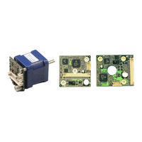
Trinamic PANdrive TMCM-013-LA Manual (27 pages)
STEPPER motor controller / driver module
Brand:
Trinamic
| Category:
Control Unit
| Size: 0 MB
Table of Contents
Table of Contents
2
1 Features
4
Table 1.1: Order Codes
4
2 Life Support Policy
5
3 Outer Description
6
Pinning
6
Figure 3.1: Pinning of TMCM-013 and TMCM-013-LA
6
Table 3.1: Pinning of TMCM-013 and TMCM-013-LA
6
Dimensions
7
Connectors
7
Figure 3.2: Dimensions for TMCM-013
7
Figure 3.3: Dimensions for TMCM-013LA
7
4 Operational Ratings
8
Table 4.1: Operational Ratings
8
Step, Direction and Disable Inputs
9
Figure 4.1: Step, Direction and Disable Inputs
9
5 Getting Started
10
Assembly of Parts
10
Motor
10
Motor Choice
10
Figure 5.1: Assembly of Parts
10
Chopper Mode 2 (PHASE)
11
Chopper Modes 0 (SPI / Default Mode) and 1 (PWM)
11
Motor Velocity
11
Table 5.1: Maximum Supply Voltage Regarding Motor Current and Inductivity
11
Connecting Motor and Power Supply
12
Power Supply Requirements
12
Figure 5.2: Maximum Supply Voltage Regarding Motor Current and Inductivity
12
Figure 5.3: Connecting Motor and Power Supply
12
Connections for Step/Direction-Mode
13
Connections for RS485 Interface
13
Figure 5.4: Contacts for Step-Direction
13
Control with Terminal Program
14
Figure 5.5: Contacts for RS485 with an Adapter
14
Figure 5.6: Connection Settings for RS485
14
Interface Installation
14
6 Functional Description
15
Disable
15
RS485 Control Interface
15
RS485 Commands
16
Table 6.1: RS485 Commands
16
Example for Test Move
17
Failure Readout (E)
17
Motor Current (C)
17
Table 6.2: Motor Current Examples
17
Table 6.3: Failure Readout in SPI Mode
17
Alert Settings (N)
18
Limit Switch (L)
18
Stallguard (G)
18
Table 6.4: Stallguard
18
Table 6.5: Limit Switch
18
Table 6.6: Alert Adjustments
18
Baud Rate (U)
19
Figure 6.1: Alarm and GPO
19
I/Os Readout (Q)
19
Output Setting (O)
19
Table 6.7: Output Adjustment
19
Table 6.8: I/Os Readout
19
Table 6.9: Baud Rate
19
Velocity Mode (V)
19
Microstep Resolution (Z)
20
Store Parameters to EEPROM (W)
20
Chopper Modes
20
Chopper Mode 0 (SPI) / Default Mode
20
Table 6.10: Adjustment of Microstep Resolution
20
Chopper Mode 1 (PWM)
21
Chopper Mode 2 (PHASE)
21
Chopper Mode 3 (Phase and SPI)
22
Chopper Mode 4 (PWM and SPI)
22
Step / Direction
22
Table 6.11: Chopper Mode 3 Switching Velocities
22
Table 6.12: External Signals and Motor Reactions
22
Direction
23
Figure 6.2: Step-Direction Signals and Motor Reactions
23
Step
23
Firmware Update
24
Figure 6.3: Step and Direction Signal
24
Figure 6.4: Firmware Update Tool
24
Reset to Factory Default
25
Option: Pseudo DC-Motor Mode (Not Supported by Software Yet)
25
Changes Required for DC Motor Mode Operation
25
Figure 6.5: Reset to Factory Default
25
Figure 6.6: GPI Wiring Scheme
25
Parameterizing with RS485
26
Motion Control
26
Figure 6.7: External Changes for Act Like DC-Motor Option
26
7 Revision History
27
Documentation Revision
27
Firmware Revision
27
Table 7.1: Documentation Revisions
27
Table 7.2: Firmware Revisions
27
Advertisement
Trinamic PANdrive TMCM-013-LA Manual (26 pages)
STEPPER motor controller/driver module 1A RMS (1.5A peak) / 30V with RS485 and step-/ direction interface
Brand:
Trinamic
| Category:
Computer Hardware
| Size: 0 MB
Table of Contents
Table of Contents
2
Features
4
Table 1.1: Order Codes
4
Life Support Policy
5
Outer Description
6
Pinning
6
Figure 3.1: Pinning of TMCM-013 and TMCM-013-LA
6
Table 3.1: Pinning of TMCM-013 and TMCM-013-LA
6
Dimensions
7
Connectors
7
Figure 3.2: Dimensions for TMCM-013
7
Figure 3.3: Dimensions for TMCM-013LA
7
Operational Ratings
8
Table 4.1: Operational Ratings
8
Step, Direction and Disable Inputs
9
Figure 4.1: Step, Direction and Disable Inputs
9
Getting Started
10
Assembly of Parts
10
Motor
10
Motor Choice
10
Figure 5.1: Assembly of Parts
10
Chopper Modes 0 (SPI / Default Mode) and 1 (PWM)
11
Chopper Mode 2 (PHASE)
11
Table 5.1: Maximum Supply Voltage Regarding Motor Current and Inductivity
11
Figure 5.2: Maximum Supply Voltage Regarding Motor Current and Inductivity
12
Motor Contact
13
Connections for Step-Direction-Mode
13
Figure 5.3: Motor Contacts
13
Figure 5.4: Contacts for Step-Direction
13
Connections for RS485-Mode
14
Figure 5.5: Contacts for RS485
14
Functional Description
15
Disable
15
RS485 Control Interface
15
RS485 Commands
16
Table 6.1: RS485 Commands
16
Example for Test Move
17
Motor Current (C)
17
Stallguard (G)
17
Table 6.2: Motor Current Examples
17
Table 6.3: Stallguard
17
Limit Switch (L)
18
I/Os Readout (Q)
18
Baud Rate (U)
18
Table 6.4: Limit Switch
18
Table 6.5: I/Os Readout
18
Table 6.6: Baud Rate
18
Store Parameters to EEPROM (W)
19
Microstep Resolution (Z)
19
Chopper Modes
19
Chopper Mode 0 (SPI) / Default Mode
19
Table 6.7: Adjusting of Microstep Resolution
19
Chopper Mode 1 (PWM)
20
Chopper Mode 2 (PHASE)
20
Step-Direction
21
Direction
21
Figure 6.1: Step-Direction Signals and Motor Reactions
21
Table 6.8: External Signals and Motor Reactions
21
Step
22
Reset to Factory Default
22
Figure 6.2: Step and Direction Signal
22
Figure 6.3: Reset to Factory Default
22
Option: Pseudo DC-Motor Mode
23
Changes Required for DC Motor Mode Operation
23
Figure 6.3: Layout Changes for Act Like DC-Motor Option
23
Parameterizing with RS485
24
Motion Control
24
Revision History
25
Documentation Revision
25
Firmware Revision
25
Table 7.1: Documentation Revisions
25
Table 7.2: Firmware Revisions
25
References
26
Advertisement
Related Products
Trinamic PANdrive TMCM-013
Trinamic TMCM-1021 TMCL
Trinamic TMCM-1076
Trinamic TMCM-1240
Trinamic TMCM-6214
Trinamic TMCM-3351
Trinamic TMCM-341
Trinamic TMCM-171
Trinamic TMCM-111-56
Trinamic StepRocker TMCM-1111
Trinamic Categories
Controller
Control Unit
Motherboard
Computer Hardware
Engine
More Trinamic Manuals
Login
Sign In
OR
Sign in with Facebook
Sign in with Google
Upload manual
Upload from disk
Upload from URL