Table of Contents

Related Manuals for Trinamic PANDrive PD-109-57


Summary of Contents for Trinamic PANDrive PD-109-57
- Page 1 PANDrive PD-109-57 57mm / NEMA-23 Stepper Motor Mechatronic Module TMCM-109-57 Electronics Manual Version: 1.10 October 17 , 2007 Trinamic Motion Control GmbH & Co KG Sternstraße 67 D - 20 357 Hamburg, Germany http://www.trinamic.com...
-
Page 2: Table Of Contents
TMCM-109 Operational Description ........................19 Calculation: Velocity and Acceleration vs. Microstep- and Fullstep Frequency ......19 Software..................................20 Revision History................................21 Documentation Revision..........................21 Firmware Revision............................21 10 References ..................................21 Copyright © 2006, TRINAMIC Motion Control GmbH & Co. KG... - Page 3 Table 5.3: Optimum motor settings ..........................15 Table 5.4: LEDs ..................................17 Table 7.1: TMC428 Velocity parameters ........................19 Table 9.1: Documentation Revisions ..........................21 Table 9.2: Firmware Revisions............................21 Copyright © 2006, TRINAMIC Motion Control GmbH & Co. KG...
-
Page 4: Features
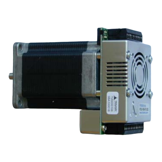
PD-109-57 / TMCM-109-57 Manual (V1.10 / October 17th, 2007) 1 Features The PANdrive PD-109-57 is a full mechatronic solution including a 57mm flange motor. It is based on the TMCM-109-57 electronics and offers RS232, RS485 or step/direction interface. The power supply, interface and the multi purpose I/Os can be connected via two pluggable screw terminal connectors. -
Page 5: Life Support Policy
Specifications subject to change without notice. Copyright © 2006, TRINAMIC Motion Control GmbH & Co. KG... -
Page 6: Electrical And Mechanical Interfacing
Height: 22mm (allow for a minimum additional 3mm distance to the motor, 4-5mm are recommended) Four mounting holes in QMOT motor configuration (M3). Mouning TMCM-109-57 holes 28.0 mm 30.0 mm 23.0 mm 5.0 mm 86.0 mm Figure 3.1: Dimensions of base PCB Copyright © 2006, TRINAMIC Motion Control GmbH & Co. KG... -
Page 7: Pandrive Dimensions
The connectors onboard of the module are 10 and a 12 pin female connector from RIACON: Type 183, RM 3.5mm Fitting male connectors with screw terminals are: RIACON Type 169, RM 3.5mm. Please refer to www.riaconnect.com for more detailed information. Copyright © 2006, TRINAMIC Motion Control GmbH & Co. KG... -
Page 8: Connecting The Module
Direction input / General purpose input 2 (positive optocoupler input) OC_GND Optocoupler ground RS485- RS485- RS485+ RS485+ RS485- RS485- (same as terminal 6) RS485+ RS485+ (same as terminal 7) Ground Ground +18..55V DC power supply Table 3.1: Connector 1 Copyright © 2006, TRINAMIC Motion Control GmbH & Co. KG... -
Page 9: Connector 2: Rs232 And Additional I/O
Connect one motor coil to connector 3 and the other motor coil to connector 4. The direction of the motor shaft can be reversed by changing the polarity of one coil. Do not connect or disconnect the motor while power on. Damage to the module may occur. Copyright © 2006, TRINAMIC Motion Control GmbH & Co. KG... -
Page 10: Operational Ratings
50% duty cycle (no cooling) Table 4.1: Operational Ratings 1) Attention: First samples (until Oct. 05) are limited to a maximum of 38V supply voltage 2) Forced cooling might be required Copyright © 2006, TRINAMIC Motion Control GmbH & Co. KG... -
Page 11: Step, Direction And Disable Inputs
TMCM-109 install the extra firmware TMCM109_StepDir.hex (please refer to chapter 5.13). It is available on TechLibCD and www.trinamic.com. The inputs disable, dir and step are electrically isolated from the module. Their functional voltages... -
Page 12: Functional Description
5V Power Supply Figure 5.1: Main parts of the TMCM-109 System Architecture The TMCM-109 integrates a microcontroller with the TMCL (Trinamic Motion Control Language) operating system. The motion control real-time tasks are realized by the TMC428. 5.1.1 Microcontroller (µC) The flash ROM of the microcontroller holds the TMCL operating system and the EEPROM memory of the microcontroller is used to permanently store configuration data, while an additional EEPROM memory holds the user TMCL programs. -
Page 13: Power Supply Requirements
(10 References). When using the RS485 interface, the devices can be daisy- chained. Bus termination resistors in the range of 100 Ohms are typically required at each of the two ends of the cables. Copyright © 2006, TRINAMIC Motion Control GmbH & Co. KG... -
Page 14: Motor Current Setting
Despite the possibility to set up to 64 microsteps, the motor physically will be positioned to a maximum of about 24 Microsteps, when operated in 32 or 64 microstep setting. Copyright © 2006, TRINAMIC Motion Control GmbH & Co. KG... -
Page 15: Optimum Motor Settings
Frequency: The maximum step input frequency is 350 kHz. The minimum logic ”0” time is 0.7 µs and the minimum logic “1” time is 2.0 µs. Copyright © 2006, TRINAMIC Motion Control GmbH & Co. KG... -
Page 16: Reference Switches
An optional cooling fan can be mounted to cope with higher environment temperatures, when problems are perceived. The 5V power supply output can be used to operate a small fan. Copyright © 2006, TRINAMIC Motion Control GmbH & Co. KG... -
Page 17: Leds
6. Turn the power on and wait until the LED flashes normally (this can take some seconds). All settings are now restored to factory default, and the module can be used again normally. Copyright © 2006, TRINAMIC Motion Control GmbH & Co. KG... -
Page 18: Putting The Tmcm-109 Into Operation
On the basis of a small example it is shown step by step how the TMCM-109 is set into operation. Users who are already familiar with TMCL and other Trinamic modules may skip this chapter. Example: The following application is to be implemented on the TMCM-109 module using the TMCL- IDE Software development environment. -
Page 19: Tmcm-109 Operational Description
The change in the pulse rate per time unit (microstep frequency change per second – the acceleration a) is given by ⋅ pulse ramp This results in an acceleration in fullsteps of: with af: acceleration in fullsteps usrs Copyright © 2006, TRINAMIC Motion Control GmbH & Co. KG... -
Page 20: Software
Windows which allows easy development of TMCL applications. All the manuals are provided on the TMC TechLib CD and on the web site of TRINAMIC Motion Control GmbH & Co. KG (http://www.trinamic.com). Also the latest versions of the firmware (TMCL operating system) and PC software (TMCL IDE) can be found there. -
Page 21: Revision History
Step / Direction firmware information (chapter 4.1 and 5.8) Table 9.1: Documentation Revisions Firmware Revision Version Comment Description 3.24 Initial Release Please refer to TMCL documentation Table 9.2: Firmware Revisions 10 References [TMCL] TMCL manual (see http://www.trinamic.com) Copyright © 2006, TRINAMIC Motion Control GmbH & Co. KG...
Need help?
Do you have a question about the PANDrive PD-109-57 and is the answer not in the manual?
Questions and answers