Table of Contents
Advertisement
Quick Links
Module for Stepper
TMCM-1110 StepRocker Hardware Manual
Hardware Version V2.30 | Document Revision V1.13 • 2021-MAR-25
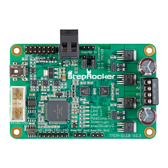
The TMCM-1110 StepRocker is a single axis motor controller/driver board for 2-phase bipolar step-
per motors. It features the TRINAMIC controller/driver chain consisting of TMC429 and TMC262
in combination with an ARM Cortex-M4™ (MK20DX128VLK7) processor. The module is intended to
be a fully functional development platform. A stepRocker can be extended to a full 3-axes system
using two additional boards, because the TMCM-1110 StepRocker board can be both, master or
slave.
Applications
• Laboratory Automation
• Manufacturing
• Robotics
Simpli ed Block Diagram
©2021 TRINAMIC Motion Control GmbH & Co. KG, Hamburg, Germany
Terms of delivery and rights to technical change reserved.
Download newest version at:
www.trinamic.com
Read entire documentation.
• Factory Automation
• Test & Measurement
• Technology evaluation
Features
• Single axis controller/driver for 2-phase
bipolar stepper motor
• 2 and 3 axes systems are possible
with additional boards con gured
as slaves
• +10. . . 30V DC supply voltage
• Up to 2.8A RMS motor current
• RS485 & USB interface
• Multi-purpose inputs and outputs
• First experiences with stepper
motors
• Hobby applications
MODULE
Advertisement
Table of Contents

Related Manuals for Trinamic TMCM-1110 StepRocker


Summary of Contents for Trinamic TMCM-1110 StepRocker
- Page 1 TMCM-1110 StepRocker Hardware Manual Hardware Version V2.30 | Document Revision V1.13 • 2021-MAR-25 The TMCM-1110 StepRocker is a single axis motor controller/driver board for 2-phase bipolar step- per motors. It features the TRINAMIC controller/driver chain consisting of TMC429 and TMC262 in combination with an ARM Cortex-M4™...
-
Page 2: Table Of Contents
TMCM-1110 StepRocker Hardware Manual • Hardware Version V2.30 | Document Revision V1.13 • 2021-MAR-25 2 / 26 Contents 1 Features 2 Order Codes 3 Mechanical and Electrical Interfacing 3.1 Size of board .......... -
Page 3: Features
ARM Cortex-M4™ (MK20DX128VLK7) processor. The module is intended to be a fully functional development platform. A TMCM-1110 StepRocker can be extended to a full 3-axes system using two ad- ditional boards, because the TMCM-1110 StepRocker board can be both, master or slave. -
Page 4: Order Codes
TMCM-1110 StepRocker Hardware Manual • Hardware Version V2.30 | Document Revision V1.13 • 2021-MAR-25 4 / 26 2 Order Codes The standard version of the TMCM-1110 StepRocker has RS485 and USB interfaces (CAN transceiver not assembled). The module is pre-programmed with TRINAMICs TMCL™ rmware with all available features. -
Page 5: Mechanical And Electrical Interfacing
TMCM-1110 StepRocker Hardware Manual • Hardware Version V2.30 | Document Revision V1.13 • 2021-MAR-25 5 / 26 3 Mechanical and Electrical Interfacing 3.1 Size of board The board with the controller/driver electronics has an overall size of 85mm x 55mm x 15mm without mating connectors. -
Page 6: Connectors
TMCM-1110 StepRocker Hardware Manual • Hardware Version V2.30 | Document Revision V1.13 • 2021-MAR-25 6 / 26 4 Connectors The TMCM-1110 StepRocker has nine connectors altogehter. There are two screw connectors for power and motor and two interface connectors (mini-USB and RS485). Furthermore, the TMCM-1110 StepRocker... -
Page 7: Power Connector
TMCM-1110 StepRocker Hardware Manual • Hardware Version V2.30 | Document Revision V1.13 • 2021-MAR-25 7 / 26 Connector Connector type on-board Mating connector type GPIO Multi-pin-connector, 14 pin, 2.54mm Female connector with 2.54mm pitch pitch Ref. switches Multi-pin-connector, 7pin, 2.54mm Female connector with 2.54mm pitch... -
Page 8: Motor Connector
TMCM-1110 StepRocker Hardware Manual • Hardware Version V2.30 | Document Revision V1.13 • 2021-MAR-25 8 / 26 Label Direction Description PWMU_0 in/out General purpose I/O (+5V compatible, default: output) PWMD_1 in/out General purpose I/O (+5V compatible, default: input) PWMU_1 in/out... -
Page 9: Reference Switch Connector (Tmc429)
TMCM-1110 StepRocker Hardware Manual • Hardware Version V2.30 | Document Revision V1.13 • 2021-MAR-25 9 / 26 Do not connect or disconnect motor during operation! Motor cable and mo- NOTICE tor inductivity might lead to voltage spikes when the motor is (dis)connected while energized. -
Page 10: Upgrade The Tmcm-1110 Steprocker For Can Communication
Table 8: USB Connector Pin Assignment 4.7 Step/Dir Input Connector (Motor 0) The TMCM-1110 StepRocker is equipped with a step/dir input connector for motor 0. Via this connector an external motion controller can be used together with the on-board driver electronics. For selecting an external motion controller instead of the on-board TMC429 motion controller two jumpers have to be set (please refer to chapter 6). -
Page 11: Step/Dir Output Connectors (Motor 1 And Motor 2)
4.8 Step/Dir Output Connectors (Motor 1 and Motor 2) The TMC429 motion controller on the TMCM-1110 StepRocker is able to control up to three stepper mo- tors. Its Step/Dir outputs (TTL level) for motor 1 and motor 2 are available via connectors Step/Dir Out 1 and Step/Dir Out 2. -
Page 12: Reset To Factory Default
Figure 3: TMCM-1110 StepRocker Programming Pads 5 Reset to Factory Default It is possible to reset all settings of the TMCM-1110 StepRocker to factory default without establishing a working communication connection. This might be helpful in case communication parameters of the preferred interface have been set to unknown values or got lost. -
Page 13: Jumper Settings
TMCM-1110 StepRocker Hardware Manual • Hardware Version V2.30 | Document Revision V1.13 • 2021-MAR-25 13 / 26 6 Jumper Settings The TMCM-1110 StepRocker offers a number of jumpers for selection of different settings in hardware. Select Select motion motor controller... -
Page 14: Leds
TMCM-1110 StepRocker Hardware Manual • Hardware Version V2.30 | Document Revision V1.13 • 2021-MAR-25 14 / 26 7 LEDs LED Description Status Label Description Power on POWER This orange LED lights up upon the power supply is available LED1 without pre-de ned functionality... -
Page 15: Communication
8 Communication 8.1 RS485 For remote control and communication with a host system the TMCM-1110 StepRocker provides a two wire RS485 bus interface. For proper operation the following items should be taken into account when setting up an RS485 network: 1. -
Page 16: Usb
Figure 7: RS485 Bus Lines with Resistor Network 8.2 USB For remote control and communication with a host system the TMCM-1110 StepRocker provides a USB 2.0 full-speed (12Mbit/s) interface (mini-USB connector). As soon as a USB-Host is connected the module will accept commands via USB. - Page 17 Especially for longer busses and/or multiple nodes connected to the bus and/or high communication speeds, the bus should be properly terminated at both ends. The TMCM-1110 StepRocker does not integrate any termination resistor. Therefore, 120 Ohm termination resistors at both ends of the bus have to be added externally.
-
Page 18: Functional Description
TMCM-1110 StepRocker Hardware Manual • Hardware Version V2.30 | Document Revision V1.13 • 2021-MAR-25 18 / 26 9 Functional Description The TMCM-1110 StepRocker is a highly integrated single axis controller/driver module for stepper motors. It can be controlled via RS485 or USB serial interfaces (CAN retro- t option) and comes with the PC based software development environment TMCL-IDE for the Trinamic Motion Control Language (TMCL™). -
Page 19: Extensions Of The Tmcm-1110 Steprocker
9.1 Extensions of the TMCM-1110 StepRocker The TMCM-1110 StepRocker can be extended for multi-axes systems with up-to 3 axes. The module itself can be con gured as master or slave. An example for a three axes system is shown below. The TMCM- 1110 StepRocker at the top is con gured as master while the other two are con gured as slave. -
Page 20: Operational Ratings And Characteristics
TMCM-1110 StepRocker Hardware Manual • Hardware Version V2.30 | Document Revision V1.13 • 2021-MAR-25 20 / 26 10 Operational Ratings and Characteristics Never Exceed the absolute maximum ratings! Keep the power supply voltage NOTICE below the upper limit of +30V! Otherwise the board electronics will seriously be damaged! Especially, when the selected operating voltage is near the upper limit a regulated power supply is highly recommended. -
Page 21: Abbreviations Used In This Manual
TMCM-1110 StepRocker Hardware Manual • Hardware Version V2.30 | Document Revision V1.13 • 2021-MAR-25 21 / 26 11 Abbreviations used in this Manual Abbreviation Description Integrated Development Environment Light Emmitting Diode Root Mean Square value TMCL TRINAMIC Motion Control Language Table 16: Abbreviations used in this Manual ©2021 TRINAMIC Motion Control GmbH &... -
Page 22: Figures Index
TMCM-1110 StepRocker Hardware Manual • Hardware Version V2.30 | Document Revision V1.13 • 2021-MAR-25 22 / 26 12 Figures Index Board Dimensions and Positions of RS485 Bus Structure with Termina- Mounting Holes (all Values in mm) tion Resistors .... -
Page 23: Tables Index
TMCM-1110 StepRocker Hardware Manual • Hardware Version V2.30 | Document Revision V1.13 • 2021-MAR-25 23 / 26 13 Tables Index TMCM-1110 StepRocker Order Code Step/Dir Output Connector Pin As- Connector Types and Mating Connec- signment .... -
Page 24: Supplemental Directives
14.5 Disclaimer: Life Support Systems TRINAMIC Motion Control GmbH & Co. KG does not authorize or warrant any of its products for use in life support systems, without the speci c written consent of TRINAMIC Motion Control GmbH & Co. KG. -
Page 25: Collateral Documents & Tools
In particular, this also applies to the stated possible applications or areas of applications of the product. TRINAMIC products are not designed for and must not be used in connection with any applications where the failure of such products would reasonably be expected to result in signi cant personal injury or death (safety-Critical Applications) without TRINAMIC’s speci c written consent. -
Page 26: Revision History
TMCM-1110 StepRocker Hardware Manual • Hardware Version V2.30 | Document Revision V1.13 • 2021-MAR-25 26 / 26 15 Revision History 15.1 Hardware Revision Version Date Author Description V1.3 2013-NOV-26 Series version with Samsung Cortex-M0 processor V2.2 2016-SEP-26 Processor changed to Cortex-M4 microcontroller V2.3...
Need help?
Do you have a question about the TMCM-1110 StepRocker and is the answer not in the manual?
Questions and answers