
Subscribe to Our Youtube Channel
Related Manuals for Kobold HEINRICH DWF-S


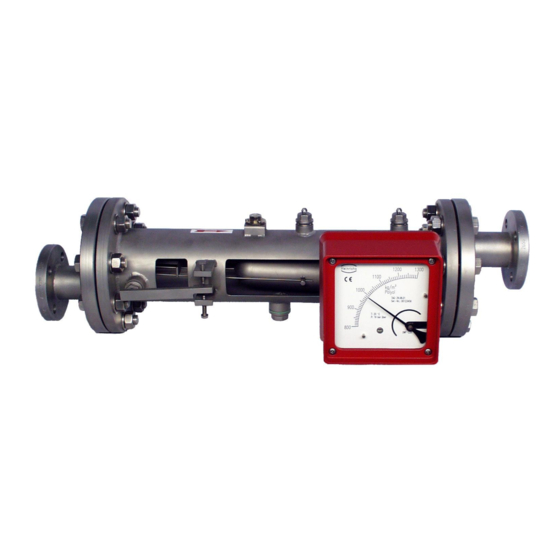
Summary of Contents for Kobold HEINRICH DWF-S
- Page 1 Density meter DWF Installation and operating manual Read these Operation Instructions thoroughly and keep them available for reference! Page 1 Installation and operating manual DWF...
-
Page 2: Table Of Contents
Table of Contents I. Steps prior to operation Safety first! Safety advisory for the user Hazard warnings Proper use of the device Returning your sensor for servicing or calibration Definition of the device Applications Operating principle and system configuration Technical Data Construction Type of dimensions Construction details... - Page 3 11. Electrical connection ® 11.1 Wiring diagram for ES transmitter (signal output 4-20 mA with HART 11.2 Wiring diagram for ES with 4-20 mA output and 2 limit contacts 11.3 Wiring diagram for ES with 4- 20 mA output, pulse output and limit contacts 11.4 Wiring diagram for two inductive limit contacts 12.
-
Page 4: Steps Prior To Operation
I. Steps prior to operation It is essential that you read these operating instructions before installing and operat- ing the device. The device is to be installed and serviced by a qualified technician only. The density - meter DWF is to be used exclusively to measure density, as well as liquid, in conjunction with technical specification by Heinrichs Messtechnik. -
Page 5: Safety First
We reserve the right to change the technical data herein in the light of any technical progress that might be made. For updates regarding the product herein, visit our website at www.heinrichs-mt.com, where you will also find contact information for the Heinrichs Messtechnik distribu- tor nearest you. -
Page 6: Proper Use Of The Device
Danger means that failure to take the prescribed precautions will result in death, severe bodily injury, or substan- tial material damage. Warning means that failure to take the prescribed precautions could result in death, severe bodily injury, or sub- stantial material damage. Caution means that the accompanying text contains important information about the product, handling the product or about a section of the documentation that is of particular importance. -
Page 7: Definition Of The Device
2. Definition of the device Vendor / Manufacture Heinrichs Messtechnik GmbH Robert – Perthel - Str. 9 D-50739 Köln Phone +49 (221) 49708 - 0 +49 (221) 49708 - 178 Internet: http://www.heinrichs-mt.com/ E-Mail: mailto:info@heinrichs-mt.com Product type and designation Mechanical density - meter DWF Manual issue date 30.06.2020 Version No. -
Page 8: Operating Principle And System Configuration
4. Operating principle and system configuration The measuring element is composed of a measuring chamber (1), measuring spring-rods (3), float (2) and a magnetic coupling system (4+5). If a liquid medium flows through the horizontal meas- uring chamber (1) and in direction to the arrow, the float surrounded by the liquid is lifted until a state of balance between the lift force (A), the measuring spring-rods (3) and the float weight (G... -
Page 9: Technical Data
5. Technical Data Equipment execution: DWF-S Stainless steel DWF-H Hastelloy Process - connection DIN / EN Body 1 Ø D=108mm 25 PN40 Body 2 Ø D=140mm 50 PN40 Body 3 Ø D=194mm 50 PN40 Max. process pressure PN16 higher pressure on request Ambient conditions dimension 700mm... -
Page 10: Construction
6. Construction Type of dimensions DN / EN Ø D (mm) A (mm) B(mm) DWF Nr. Page 10 Installation and operating manual DWF... -
Page 11: Construction Details
Construction details Pos. Bezeichnung Pos. Bezeichnung process connection - flow inlet measuring scale spring-rods - float suspension follow magnet indication system measuring range adjustment 10 indication part compl. measuring spring -rods 11 coupling magnet 12 float measuring chamber closing screw - Transport-safety device G1/2" 13 zero point adjustment compl. -
Page 12: Output
Output Various electrical contact makers or converter may be installed in the indicator unit. KEI 1 or KEI 2 limit switches 1 or 2 limit switches, type SJ 3,5N, make Pepperl + Fuchs to the connection to NAMUR electrical circuits to EN 60974-5-6. (special switch possible, e.g. -
Page 13: Operating Conditions
Influence of ambient temperature Without electrical equipment and with limit switches without influence With ES transmitter: +/- 0.5 % / 10 K reference temperature 22°C Influence of fluid temperature Deviations in fluid temperature from the temperature observed during calibration can result in a propor- tional display fault because of the corresponding change in density. -
Page 14: Mounting/Start-Up
Mounting/start-up The device must be mounted in horizontal direction of flow from left to right The nominal size of the device and that of the pipes must be the same. The pressure stages and, hence, the dimensions of the flanges must coincide. The surface roughness of the flange-sealing surface must be suitable for the prescribed gaskets. -
Page 15: Device Settings
Device settings The measuring equipment is delivered ready for operation according to your order specifications. The limit transducers are set to the desired values. If you have submitted no requirements, the basic setting for: 1 contact device: - Minimum contact switching point at 10% of descending density (damped / closed-circuit principle). -
Page 16: Operation In Hazardous Areas
10. Operation in hazardous areas 10.1 Without electrical equipment The basic version of the density meter is a non-electrical device without its own ignition sources and meets DIN EN 13463-1 requirements. It can be used in hazardous areas that require Category 2 equip- ment. -
Page 17: Example For Built-In Sensor Type Es
10.2.2 Example for built-in sensor Type ES: = 70°C = 60°C = 0.2 Tamb Tamb 10.3 Marking for the electric device 10.3.1 Marking when the SJ 3,5...N... -
Page 18: Electrical Connection
11. Electrical connection Wiring To connect the auxiliary power, remove the indicator cover, insert the connector cable into the cable gland and attach it to the terminals according to terminal diagram. Tighten the cable gland securely, remount the indicator cover and close it tightly. ®... -
Page 19: Wiring Diagram For Es With 4-20 Ma Output And 2 Limit Contacts
11.2 Wiring diagram for ES with 4-20 mA output and 2 limit contacts 11.3 Wiring diagram for ES with 4- 20 mA output, pulse output and limit contacts Page 19 Installation and operating manual DWF... -
Page 20: Wiring Diagram For Two Inductive Limit Contacts
11.4 Wiring diagram for two inductive limit contacts Page 20 Installation and operating manual DWF... -
Page 21: Indicator Unit
12. Indicator unit Analog indicator approx. 90° with pointer Customized product scale ES transmitter with freely programmable user interface Parameters may be changed based on the ES Operating Instructions. 13. Auxiliary power see Electrical connection 14. CE mark The measuring system meets the statutory requirements of the following EU directives: Directive 2014/34/EU (Equipment and Protective Systems for Use in Potentially Explosive Atmospheres), the Elec- tromagnetic Compatibility (EMC) Directive 2014/30/EU and the Pressure Equipment Directive 2014/68/EU. -
Page 22: Safety Advisories
18. Safety advisories 18.1 Intended purpose The DWF density-meter may be used only for density measurements of fluid media. The manufacturer shall not be liable for damages that may result from unintended or inappropriate use. When dealing with an aggressive medium, clarify the material durability of all wetted parts. When using the device in hazardous areas, follow the applicable national installation rules. -
Page 23: Replacement Parts
21. Replacement parts The following parts can be ordered as replacement parts: Indicator cover with window/gasket/screws Scale with standard scaling (required serial number) Pointer Limit value indicator Pointer stop Limit value initiator 22. Packaging, storage, transport Carefully unpack the device to avoid damaging it. -
Page 24: Exploded Views
23. Exploded views 23.1 Complete indicator unit, local with scale Name Part no. Mounting plate with 1 thread M 20 x 1.5 Bearing unit Fixing screws for bearing unit Dummy plug M 20 x 1.5 Cable gland Scale, product scale according to original shipment (order no. -
Page 25: Complete Indicator Unit With 2 Sj 3,5 N Limit Transducers
23.3 Complete indicator unit with 2 SJ 3,5 N limit transducers Name Part no. Mounting plate with 1 thread M 20 x 1.5 Bearing unit Fixing screws for bearing unit Dummy plug M 20 x 1.5 Cable gland Scale, product scale according to original shipment (order no. -
Page 26: Declaration Of Conformity
24. Declaration of conformity Page 26 Installation and operating manual DWF... - Page 27 Page 27 Installation and operating manual DWF...
- Page 28 Page 28 Installation and operating manual DWF...
-
Page 29: Notes
25. Notes Page 29 Installation and operating manual DWF... -
Page 30: Decontamination Certificate For Device Cleaning
26. Decontamination certificate for device cleaning Company name:............Address:............Department:..............Name (Contact):........... Phone: ..............Information pertaining to the enclosed DWF Model DWF............. Was operated using the following fluid: ................................... In as much as this fluid is *: toxic health hazard- corrosive radioactive safe...
Need help?
Do you have a question about the HEINRICH DWF-S and is the answer not in the manual?
Questions and answers