Table of Contents
Advertisement
Quick Links
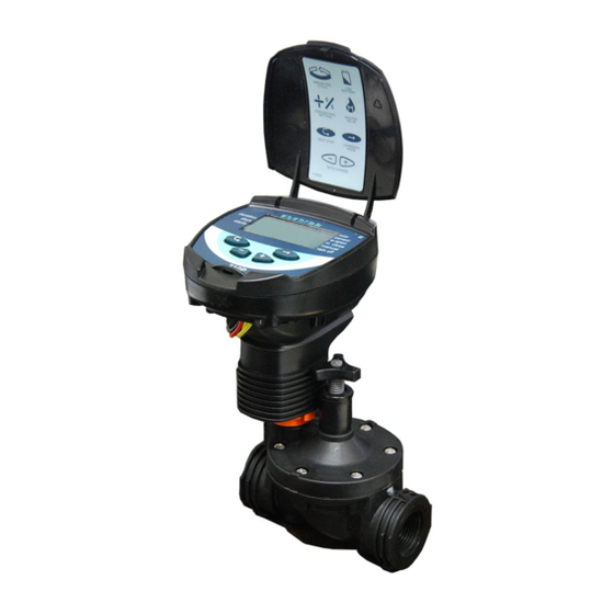
Single, Four & Six Station
Battery Operated Controllers
Features
• Weekly or cyclical program
• Four start times per day in weekly mode
• Irrigation duration – from 1 minute to 12 hours in 1 minute increments
• Water budget from -95% to +95% in 5% increments
• Semi-automatic or manual operation
• Rain delay up to 30 days
• Simple, four button keypad programming
• Withstands harsh climatic conditions
° Completely waterproof
• Can be mounted on a valve or on valve box wall
• Available with 3/4", 1", 1 1/2", 2" valves and 3/4" and
1" actuators to convert most manual antisiphon valves
• Available with rain sensor connection
• Operates using 1, 9-volt alkaline battery
• Up to 2 year battery life
• Uses the DIG R710DC solenoid with 18" wire
with internal manual bleed
740-000
710, 740 & 746 Series
710-075
710-011
Advertisement
Table of Contents

Subscribe to Our Youtube Channel
Related Manuals for DIG Irrigation-Mart 710 Series


Summary of Contents for DIG Irrigation-Mart 710 Series
- Page 1 Single, Four & Six Station Battery Operated Controllers Features • Weekly or cyclical program • Four start times per day in weekly mode • Irrigation duration – from 1 minute to 12 hours in 1 minute increments • Water budget from -95% to +95% in 5% increments • Semi-automatic or manual operation • Rain delay up to 30 days • Simple, four button keypad programming • Withstands harsh climatic conditions ° Completely waterproof • Can be mounted on a valve or on valve box wall • Available with 3/4”, 1”, 1 1/2”, 2” valves and 3/4” and 1” actuators to convert most manual antisiphon valves • Available with rain sensor connection • Operates using 1, 9-volt alkaline battery • Up to 2 year battery life • Uses the DIG R710DC solenoid with 18” wire with internal manual bleed 710-011 740-000 710-075...
-
Page 2: Table Of Contents
table of contents IntRODUCtIOn ……………………………………………………………… 3 1. About the controllers …………………………………………………… 3 2. Parts identification ……………………………………………………… 3 3. System components …………………………………………………… 4 4. Valve or wall mounting ………………………………………………… 4 4.1 Valve mounting …………………………………………………… 4 4.2 Wall mounting … …………………………………………………… 4 5. Installation … …………………………………………………………… 5 5.1 Valve and solenoid assembly and installation … ……………………… 5 5.2 4 & 6-station installation …………………………………………… 7 5.3 Actuator assembly and installation …………………………………... -
Page 3: Table Of Contents
After reading this manual and having been familiarized with the basic functionality of the controller, this manual can be used as a reference for less common tasks in the future. 1. about the controllers the 700 series battery operated controller’s employ the latest engineering improvements for better operation. the 700 series controllers are available in single, four and six-station configurations and provide advanced and simple programming features for all types of light commercial applications. the 700 series is powered by 1, 9-volt battery and wrapped in a compact housing design that provides enhanced waterproofing capability. the 710, 740 and 746 controllers operate in conjunction with DIG’s 2-wire DC latching solenoid (R710DC). DIG in-line globe valves are also available in sizes 3/4” to 2” with the solenoid pre-installed. 2. Parts identification 1. Cover 2. Battery compartment cover 3. Controller display 4. Programming buttons 5. Controller bracket 6. Valve mounting bracket 7. Wall mounting bracket 8. Solenoid wires 9. Sensor wires (optional) 10. Master valve wires (740 & 746 only) 4-Station... -
Page 4: System Components
3. system comPonents To properly install 700 series controllers the following components are needed: OPtIOn 1 • 710-000 Single station controller with R710DC solenoid or with DIG in-line valve assembly • Optional valve adapter (see below) OPtIOn 2 • 740-000 Four station or 746-000 Six station controller • DIG in-line valve assembly or R710DC solenoid (one for each valve used) if using existing valves • Optional valve adapter (see below) Model #P00-996 Model #P00-995 VALVE ADAPtER • Models P00-995 and P00-996 are used with RAIn BIRD, DV, PGA, PEB (3/4” and 1” only), GB, EFB-CP, BPE, O-ring 200-021 PESB and ASVF valves (adapter sold separately). Model #03-077 4. -
Page 5: Installation
5. installation 5.1 VALVE ANd SOLENOId ASSEMBLy NOTE: Suggested operating pressure: 10-120 PSI (.7 to 10.5 BAR) Use DIG’s DC valve assembly or solenoid model R710DC. 1. Shut off the mainline to the valve. 2. Install the DIG valve and latching solenoid assembly or unscrew the conventional solenoid from the valve used and remove the solenoid housing, solenoid stem, plunger, spring, and O-ring (if necessary). 3. Converting SUPERIOR valves: First, remove the SUPERIOR solenoid and O-ring and replace with one O-ring (DIG part #30-492) inside the solenoid thread cavity (this O-ring is included). Install the adapter then, slip the manual handle into the adapter. Attach the solenoid with the plunger and position the handle at a 45° angle towards the valve outlet (see B1-C). this creates a manual lever, helpful for manual on/off. Firmly tighten the Additional system components Additional system components solenoid by hand, but do not over tighten. Additional system components 4. Converting IRRItROL (HARDIE) valves: Leave Irritrol manual handle in place (not applicable for 205 series). Screw the provided adapter into Irritrol adapter or directly into valve (205 series only). DO nOt use the orange manual handle provided with this installation. Screw the R710 DC solenoid with the plunger into the adapter. 5. Converting RAIn BIRD valves: Unscrew and remove Rain Bird AC solenoid. Install adapter model P00-996 into a Rain Bird valve and tighten the adapter with a wrench. next, install the R710DC latching solenoid directly into the adapter clockwise and hand tight. DO nOt... - Page 6 USE CONVENTIONAL dry-SpLICE WATErprOOF CONNECTOrS. Leave some slack on each side of the wires so that repairs, if needed, can be carried out easily (see d). NOTE: Subsequent 710 Models (only) will have the solenoids hard wired into the controller eliminating the need for waterproof connectors. 7. Mount the controller – see section 4 on page 4 for wall or valve mounting (see E, G, h). 8. After installation is complete, turn on the water supply and pressurize the mainline. the valves will open momentarily and then shut off. test each valve in manual operation by moving the manual handle from left to right to open and right to left to close. Do this to make sure that the valve is operating correctly (see F).
-
Page 7: 6-Station Installation
5.2 4 & 6-station instaLLation (740-000 & 746-000 onLy) notE: Each zone requires a dedicated pair of wires from the controller. the four (740-000) and six (746-000) station controllers have red and black pairs of wires numbered for each valve. notice there are 2 extra sets of wires. One set of wires (black and red) is stamped with the letter M representing the master valve, and one set of wires (yellow) with the letter S representing the rain sensor connection. Connect each of the controller wire sets (each with red and black) to each solenoid wire (red and black). Connect the red wire from the controller to the red wire on the solenoids and each of the black wires from the controller to each black wire on the solenoids using waterproof connectors (see I). NOTE: If you install a master valve, it will open automatically with each valve. no special programming needed. NOTE: Do not strip the master valve or sensor wires unless using master valve or rain sensor. IMpOrTANT: If a valve remains open in manual operation, you may need to examine the solenoid and the adapter to see that they are installed correctly. Make sure the adapter is firmly secured but do not over tighten the solenoid to the valve (and do not cross thread the adapter into the solenoid cavity). NOTE: the solenoid operates only with standard 2-way normally closed valves. CAUTION: For all valves with built-in internal manual bleed lever, make sure the lever is in closed position. Do not move the manual lever after installing the solenoid using the valve adapter. If the manual lever on the valve is used, it can damage the adapter outlet port causing the valve to stay open. -
Page 8: Actuator Assembly And Installation
5.3 dC ACTUATOr ASSEMBLy ANd INSTALLATION NOTE: Subsequent 710 Models (only) will have the solenoids hard wired into the controller eliminating the need for waterproof connectors. the actuator comes factory assembled to fit 3/4” CHAMPIOn and ORBIt brass manual anti-siphon valves. Included in the package are adapters to fit 1” CHAMPIOn, ORBIt brass manual anti-siphon valves, and 3/4” and 1” RAIn BIRD and ORBIt plastic manual anti-siphon valves. Maximum operating pressure: 125 pSI NOTE: Please select the proper adapter. warning: FaiLUrE TO USE waTErprOOF cOnnEcTOrS wiLL vOid ManUFacTUrEr’S warranTy. -
Page 9: Adapter/Seat Washer Installation
5.4. AdApTEr/SEAT WAShEr INSTALLATION the actuator is factory setup to fit 3/4 in. brass manual anti-siphon valves. to install the actuator on 1 in. brass anti-siphon valves and all other manual plastic valves, the 3/4 in. seat washer Valve and adapters must be removed and replaced body with the 1 in. adapter and seat washer which are Figure A included in this box. 1. turn the actuator so that the seat washer and the 3/4 in. threaded adapter facing up. 2. Using pliers, remove the seat washer screw by turning counter clockwise and pull off the 3/4 in. seat washer assembly (see Figure A). 3. Push the 3/4 in. threaded adapter down (see Figure B Figure B). 4. Place your thumb on one side of the retainer clip and with a pair of pliers grip the other side of the retainer clip and pull outwards then upwards, removing it from the base of the 3/4 in. adapter threaded. next, pull off the 3/4 in. threaded adapter from the actuator stem Figure C (see Figure C). 5. Install the 1 in. threaded adapter by pushing it onto the actuator stem and making sure the notch on the adapter lines up with the notch on the stem of the actuator (see Figure D). 6. Spread the retainer clip with your thumbs and push the retainer into the adapter until it clicks Figure D (see Figure E). 7. Install the 1 in. seat washer assembly making sure the plastic is on top and the rubber is facing down. Insert the seat washer screw into the bottom of the actuator stem and tighten with pliers by turning clockwise (see Figure E). -
Page 10: Using A Sensor
inSTaLLaTion Flow control knob 1. Shut off main water supply. 2. Remove the manual stem from the existing valve and manual Stem temporarily remove the anti-siphon cap (see A). anti-Siphon Cap 3. Replace any existing worn washers with the new ones provided. 4. Install the actuator with the controller into the manual anti-siphon valve body by turning actuator clockwise. tighten firmly, but do not over tighten (see B). 5. turn on main water supply. 6. Splice the solenoid hot wires (red) to the controller color-coded wires (red). Splice the solenoid white wire to the single incoming black wire. USE CONVENTIONAL dry-SpLICE WATErprOOF CONNECTOrS. Leave slack on each side of the wires so that repairs, if needed, can be carried out easily. 7. After installation is complete, test each valve in manual mode through the controller (see section 16 on page 16). Adjust the flow by turning the flow control knob, making sure that each valve is operating correctly. 8. Program the controller (see section 8 on page 12). 6. usinG a sensor 1. Carefully strip each of the controller’s two yellow sensor wires. 2. Select a normally open sensor, or configure the sensor to be normally open (see sensor instructions). 3. Connect 1 of each yellow wire from the controller to each of the normally open wires from the sensor USING WATErprOOF CONNECTOrS. -
Page 11: Battery Installation
7. battery installation Rotate the battery compartment cover handle counter clockwise to the “11 o’clock” position to remove the cover (see A). Insert one 9-volt alkaline battery onto the terminal clips and slide the battery into the sleeve. Insert the battery into the battery compartment and reinstall the cover (see B-C). the controller display appears briefly followed by a water droplet on the lower left side of the display. the droplet will flash momentarily and shut off. When the display flashes “12:00” the controller is ready to be programmed. IMpOrTANT: to replace the battery compartment cover, insert the battery compartment cover with the handle in the “11 o’clock” position and then rotate the cover 1/4” clockwise to avoid breaking the cover guide pin. IMpOrTANT: Do not install battery before splicing controller/solenoid wires (see section 5). C... -
Page 12: Programming
8. ProGramminG this section explains the programming features, use of buttons and the steps necessary to assign irrigation schedules. to program the controller use the left button to select the desired programming mode, the right button to make the entry flash and the plus minus buttons to change the value. Note: Only a flashing character can be changed. DIG controllers are programmed with the aid of four buttons: Use to select the desired programming mode Use to lower the value of the selected parameter (e.g. deducts an hour) U se to raise the value of the selected parameter (e.g. adds an hour) U se to select the parameter to be changed (hour, minute, etc.). to implement the changes, the selected parameter must be flashing. If no changes are implemented, the controller will always revert to the main screen. 9. settinG current time and day of the WeeK to enable the controller to operate properly, the current time and current day of the week must first be set. the steps below explain how to set the day and time. Press and the hour digit will flash. Use the or to set the current hour (note AM and PM designations). Press and the minute digit flashes. Set the current minute using or . Press and a flashing arrow will appear under “M” for “Monday”. Use the or to move the arrow to current day. Press to proceed... -
Page 13: Time Format (Switching Between Am/Pm And 24 Hour)
10. time format (sWitchinG betWeen am/Pm and 24 hour) the default time format is AM/PM. there is also a 24 hour time format option. It is a simple process to switch between the two formats. Press several times until appears. Press and the hour digit will flash. Press the and simultaneously. the clock reading switches from AM/PM to a 24 hour time display or vice versa. NOTE: the time display format can be switched at any step in the programming process. 11. ValVe selection (740-000 & 746-000 only) the four and six station controllers allow each station to be independently programmed. First select the desired valve following these steps: Press until appears with an arrow above the valve number. Press . the arrow above the valve number will flash. Move the flashing arrow to the desired valve number by pressing or . Press to proceed to the next step. to program other station, first select the station number then repeat programming the station. -
Page 14: Selecting Watering Frequency
13. selectinG WaterinG frequency this setting determines which days the controller will operate. Choose either A) Watering According to the days of the Week or B) One-time Irrigation or C) Cyclical Irrigation. Press until appears. Press and a flashing arrow appears at the top of the display, under Monday. At this stage select one of 3 options: A. Watering according to the days of the week B. One-time only watering or cyclical watering C. Cyclical Mode A. WATErING ACCOrdING TO ThE dAyS OF ThE WEEk to select a watering according to the days of the week, press and move the flashing arrow to the desired day of the week. Press and the... -
Page 15: Setting A Start Time - Water According To Days Of Week
C. CyCLICAL MOdE TO WATEr EVEry x dAyS Press until appears. Press several times (to advance all the days of the week) until appears, and flashes on the display. With the display flashing, press or . the number of days between watering appears on the display. For example, if “every 30 days” appears, watering will take place once every thirty days for the irrigation period as set in duration. to change the number of days press or . Press to proceed to the next step. 14. settinG a start time – WaterinG accordinG to days of WeeK In this step, up to 4 separate irrigation start times can be programmed in the weekly mode (watering according to the days of the week). Press until StARt I appears. the word OFF (or the last start time entered) appears. Press the word OFF flashes. Press or to set the desired start time hour (note AM... -
Page 16: Setting A Start Time - Cyclical Or One-Time Watering
15. settinG a start time – cyclical or one-time WaterinG (With oPtion to delay ValVe start time) this program is used to pre-set the valve start time (only one start time available) and the number of day(s) to delay the valve start time. the number of day(s) to delay option will appear on the display to the right of the irrigation start time above the word “days”. In this feature 0 days = program starts today; where 1 = program starts tomorrow, etc. (start can be delayed up to 30 days). Press until StARt I appears or the last opening time entered appears on the display. Press and the hours and the AM/PM digits flash. Set the desired opening hour by pressing the or (note: AM and PM designations appear to the left of the hour digits). Press and the minute digits flash. Repeat the same steps for setting the minutes. to delay watering press again. the number above “days” flashes. Press or to change the number of days to delay the start time from today. 16. -
Page 17: Rain Off (Shutdown)
for the pre-programmed duration. If watering needs to be stopped before the full duration; simply press the button again. method 2: Press until appears. Press to open the valve. the word On is displayed and a water droplet appears on the lower left side of the display. After 5 seconds, a count down of the remaining irrigation duration appears. to close the valve manually before the end of the manual cycle press until On appears again. Press to close the valve. 17. rain off (shutdoWn) this option is used to temporarily suspend the controller operation. the irrigation schedule remains stored in the controller memory, but is not implemented until the suspension is canceled. the suspension option disables the valve. Press until appears. Press and hold down for 5 seconds until appears flashing. the controller is now suspended. to restore control to the controller, press until appears, and then press and hold down the until the disappears. RAIn OFF can be used while a valve has been activated. If an attempt is made to operate the valve manually while the controller has been suspended, or if the valve is programmed to open, the word “rain” appears, and the valve will not open. -
Page 18: Budget
18. budGet Watering durations may need to be increased in hot weather and decreased in cool or wet weather. this can be done without affecting programmed schedules by specifying a percentage increase or decrease. Press until appears, wait until no digit is flashing. Press simultaneously until 00+% is displayed. Press and the 00 flashes. Press or to increase or decrease the percentage as necessary (in 5% increments from -95% to +95%). Displayed on the “now ” screen is +% or –% when a budget choice is entered. 19. sensor oPeration to connect a sensor to the 700 series controllers, see section 6 on page 9. In the current time mode, the sensor icon will appear when the sensor is tripped and “ FF” will appear in the manual mode if a manual start is attempted. 20. missinG ProGram data During “manual” operation via the irrigation controller “no Prog” appears on the display (see section 16 on page 15), indicating that no time duration has been set for the valve. In this case, automatic opening of the valve is disabled. -
Page 19: Flashing Low Battery Warning
21. flashinG loW battery WarninG When the batteries are low, a flashing battery icon appears. In this state, the batteries still enable valve operation, but must be promptly replaced. After replacing the batteries, press any button to resume controller operation. Programmed data is retained if batteries are replaced within a 30 second time period. hINT: Simply replace one battery at a time. 22. constant loW battery WarninG When the batteries are low and not replaced in a timely manner, the battery icon is displayed. All other display elements disappear and all valves are closed. Replace batteries promptly, and press any button to resume controller operation. Programmed data is retained if batteries are replaced within a 30 second time period. -
Page 20: Maintenance, Troubleshooting And Repairs
23. maintenance, troubleshootinG and rePairs • Batteries should be removed if the irrigation controller will not be operated for a prolonged period. • Under normal usage, batteries (alkaline) will last for a minimum of 1 year to a maximum of 2 years. • It is good operating practice to replace old batteries with new ones at the start of the irrigation season. • In-line valve recommended operating water pressure range: 10-80 PSI. • In-line valve operating pressure range: 10-150 PSI. • Actuator recommended operating water pressure range: 25-90 PSI. prOBLEM: In-line valve does not open during automatic operation or during “manual” operation via irrigation controller CAUSE: Weak battery SOLUtIOn: Replace battery prOBLEM: no display CAUSE: Weak battery SOLUtIOn: Replace battery prOBLEM: Valve does not close despite solenoid activation CAUSE: Valve is installed backwards SOLUtIOn: Reverse valve prOBLEM: In-line valve does not close despite solenoid activation CAUSE: Outlet flow may be too low S OLUtIOn: Increased flow rate by adding drip emitters or micro sprinklers CAUSE: the solenoid orifice or adapter inlet if used is blocked SOLUtIOn: Flush and clear port prOBLEM: In-line valve does not fully close CAUSE: Debris stuck in diaphragm SOLUtIOn: Remove bonnet and diaphragm and clean diaphragm... -
Page 21: Warranty
COrpOrATION ShALL IN NO EVENT BE LIABLE FOr ANy INCIdENTAL Or CONSEQUENTIAL dAMAGES OF ANy kINd; ThE SOLE OBLIGATION OF dIG BEING LIMITEd TO rEpAIr Or rEpLACEMENT OF dEFECTIVE prOdUCTS. SOME STATES dO NOT ALLOW ThE ExCLUSION Or LIMITATION OF INCIdENTAL Or CONSEQUENTIAL dAMAGES, SO ThE ABOVE LIMITATION Or ExCLUSION MAy NOT AppLy TO yOU. -
Page 22: Technical Assistance
25. technical assistance Should you encounter any problem(s) with this product or if you do not understand its many features, please refer to this instruction manual first. If further assistance is required, DIG offers the following customer support: tECHnICAL SERVICE USA • Irrigation-Mart's Technical Service Team is available to answer questions from 8:00 AM to 5:00 PM (CST) Monday-Friday (except holidays) at 800- SAY-RAIN. • Questions can be emailed to info@irrigation-mart.com. • Specification documents and manuals are available for downloading at www.digcorp.com.
Need help?
Do you have a question about the Irrigation-Mart 710 Series and is the answer not in the manual?
Questions and answers