Table of Contents
Advertisement
Quick Links
Advertisement
Table of Contents

Subscribe to Our Youtube Channel
Summary of Contents for pandaboard OMAP 4 Series
- Page 1 OMAP 4 PandaBoard System Reference Manual Arrow.com. Downloaded from...
- Page 2 DEVELOPMENT, DEMONSTRATION, OR EVALUATION PURPOSES ONLY and is not considered by PandaBoard.org to be a finished end-product fit for general consumer use. Persons handling the product(s) must have electronics training and observe good engineering practice standards. As such, the goods being provided are not intended to be complete in terms of required design-, marketing-, and/or...
- Page 3 The user assumes all responsibility and liability for proper and safe handling of the goods. Further, the user indemnifies PandaBoard.org from all claims arising from the handling or use of the goods. Due to the open construction of the product, it is the user’s responsibility to take any and all appropriate precautions with regard to electrostatic discharge.
- Page 4 Reference Manual DOC-21010 WARRANTY: The PandaBoard is warranted against defects in materials and workmanship for a period of 90 days from purchase. This warranty does not cover any problems occurring as a result of improper use, modifications, exposure to water, excessive voltages, abuse, or accidents. All boards will be returned via standard mail if an issue is found.
- Page 5 About This Manual This manual should be used by software and hardware developers of applications based on the OMAP4430 chipset. This document describes the OMAP4430 PandaBoard hardware. This document also gives the user information about the different interfaces on the OMAP4430 PandaBoard.
- Page 6 Revision 0.4 OMAP 4 PandaBoard System September 22, 2010 Reference Manual DOC-21010 Revision History Revision History Changes Date Preliminary Release 24 Aug. 2010 Re-release after initial feedback 2 Sept. 2010 Document Board ID bits 8 Sept. 2010 Add information for schematics, PCB information 22 Sept.
-
Page 7: Table Of Contents
Reference Manual DOC-21010 Contents Introduction ............................... 11 OMAP4430 PandaBoard Overview ......................12 Overview of the OMAP4430 PandaBoard Kit Contents................13 OMAP4430 PandaBoard Architecture ...................... 14 Overview of the PandaBoard Architecture....................14 System Clock Distribution ........................17 OMAP4430 Processor ..........................17 TWL6030 Power Companion IC....................... - Page 8 Camera Expansion Connector Pin Multiplexing.................. 56 3.2.3 Expansion Connector (J3 & J6) Pin Multiplexing ................57 OMAP4430 PandaBoard Key Components ....................59 OMAP4430 PandaBoard Key Component Datasheet URLs ..............60 3.4.1 Connector Datasheets........................... 60 3.4.2 Key Electronic Component Datasheets....................61 Test/Debug Information ..........................
- Page 9 Reference Manual DOC-21010 Figures Figure 1 – OMAP4430 PandaBoard Architectural Block Diagram ............15 Figure 2 – OMAP4430 PandaBoard (Top View) ..................16 Figure 3 – SYSBOOT[5:0] Resistor Locations ..................24 Figure 4 – PandaBoard Input Power Circuitry Block Diagram..............25 Figure 5 –...
- Page 10 C4 Device Addresses....................51 Table 18: Board ID Read Values ........................ 52 Table 19: PandaBoard OMAP4430 Pin Multiplexing ................56 Table 20: Camera Expansion Connector (J17) Pin Multiplexing Options ..........57 Table 21: Expansion Connector (J3 & J6) Pin Multiplexing Options ............58 Table 22: OMAP4430 PandaBoard Key H/W Components...............
-
Page 11: Introduction
DOC-21010 1 Introduction This document is the System Reference Manual for the PandaBoard, a low cost OMAP4430 based board supported through http://pandaboard.org. This includes system setup and debugging. This document provides detailed information on the overall design and usage of the PandaBoard from the System perspective. -
Page 12: Omap4430 Pandaboard Overview
DOC-21010 OMAP4430 PandaBoard Overview PandaBoard is an OMAP4430 platform designed to provide access to as many of the powerful features of the OMAP4430 Multimedia Processor as possible, while maintaining a low cost. This will allow the user to develop software to utilize the features of the powerful OMAP4430 processor. In addition, by providing expandability via onboard connectors, the PandaBoard supports development of additional capabilities/functionality. -
Page 13: Overview Of The Omap4430 Pandaboard Kit Contents
The OMAP4430 PandaBoard kit contains the following items: 1 PandaBoard Board packing material 1 Shipping Box The following items can be used with the PandaBoard, but are NOT included in the kit. USB Cable (mini-AB to Type A) HDMI Cable (Type A) DB-9 Male-to-female cable (null-modem) HDMI-A Male to DVI-D Cable DC wall supply (+5Vdc) –... -
Page 14: Omap4430 Pandaboard Architecture
See Figure 2 on page 16 for a top side view of the Panda Platform. The core components of the PandaBoard will be discussed in this section of the document. This would include the OMAP4430 Processor and its POP LPDDR2 memory, the input clock circuitry, the TWL6030 Power Companion IC, and the TWL6040 Audio Companion IC. -
Page 15: Figure 1 - Omap4430 Pandaboard Architectural Block Diagram
Connector (J18) CLK32KG LS Research WL1271 Module (WLAN, BT, FM) JTAG/Trace RS-232 Female Connector 9-pin D-Sub (J8) (P4) Figure 1 – OMAP4430 PandaBoard Architectural Block Diagram Page 15 of 83 Arrow.com. Arrow.com. Arrow.com. Arrow.com. Arrow.com. Arrow.com. Arrow.com. Arrow.com. Arrow.com. Arrow.com. -
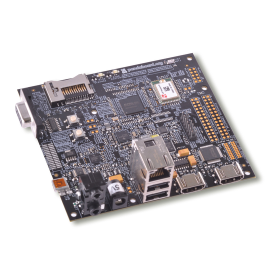
Page 16: Figure 2 - Omap4430 Pandaboard (Top View)
Revision 0.4 OMAP 4 PandaBoard System September 22, 2010 Reference Manual DOC-21010 Figure 2 – OMAP4430 PandaBoard (Top View) Page 16 of 83 Arrow.com. Arrow.com. Arrow.com. Arrow.com. Arrow.com. Arrow.com. Arrow.com. Arrow.com. Arrow.com. Arrow.com. Arrow.com. Arrow.com. Arrow.com. Arrow.com. Arrow.com. Arrow.com. Downloaded from... -
Page 17: System Clock Distribution
DOC-21010 System Clock Distribution The OMAP4430 PandaBoard implements a 38.4 MHz 1.8V CMOS square-wave oscillator that directly drives the FREF_SLICER_IN input (ball AG8) of the OMAP4430 processor and the MCLK input to the TWL6040 Audio Companion IC. This clock is used as an input to the PLLs within the OMAP4430 processor so that it can generate all the internal clock frequencies required for system operation. -
Page 18: Twl6030 Power Companion Ic
Platform. Shown below is a feature list of the major functions/interfaces provided by the TWL6030 device that are utilized on the Panda platform. This list below doesn’t include all device functionality, just that which is used on the PandaBoard. A power management system (FSM) 1 HS-I2C interface (≤... -
Page 19: Twl6030 V1V8 Smps Output
2.4.2 TWL6030 V1V8 SMPS Output The TWL6030 V1V8 SMPS provides the I/O voltage for the PandaBoard (net name VIO_1v8). This is a 1200mA SMPS that provides a 1.8V output that is used to power many balls on the OMAP4430 processor that set the I/O voltage for the device. It also sources onboard peripherals that require an operating voltage referenced to processor I/Os. -
Page 20: Twl6030 Clock Circuitry
USB transceiver. The only ball powered by this LDO is the VDDA_USBA0OTG_3P3V ball (ball A5). The VPP LDO is adjustable LDO that powers the VPP_CUST and VPP_STD balls on OMAP (balls J8 and Y22). This LDO is only needed for eFuse operations and can be left disabled for normal PandaBoard operation. 2.4.7 TWL6030 Clock Circuitry The TWL6030 has an 32.768 KHz crystal connected across its OSC32KIN and OSC32KOUT balls. -
Page 21: Sysboot Configuration
Revision 0.4 OMAP 4 PandaBoard System September 22, 2010 Reference Manual DOC-21010 o Earpiece Output o FM Input o Aux Output o Hands-free 8 ohm driver o Dual Vibrator Misc Control o GPO o I2C (high speed) o Power on/off... -
Page 22: Table 2: Sysboot[5:0] Definitions - Peripheral Preferred Booting
Revision 0.4 OMAP 4 PandaBoard System September 22, 2010 Reference Manual DOC-21010 Booting Devices Order SYSBOOT[5:0] 000000 MMC2(1) 000001 000010 XIPWAIT 000011 NAND 000100 EMIF 000101 MMC1 000110 OneNAND 000111 OneNAND MMC2(1) 001000 UART MMC2(1) 001001 UART 001010 UART XIPWAIT... -
Page 23: Table 3: Sysboot[5:0] Definitions - Memory Preferred Booting
Revision 0.4 OMAP 4 PandaBoard System September 22, 2010 Reference Manual DOC-21010 Booting Devices Order SYSBOOT[5:0] 100000 MMC2(1) 100001 100010 XIPWAIT 100011 NAND 100100 EMIF 100101 MMC1 100110 OneNAND 100111 OneNAND MMC2(1) 101000 MMC2(1) UART 101001 UART 101010 XIPWAIT UART... -
Page 24: Miscellaneous Power Circuitry
The input power circuitry may be found on sheet 2 of the board schematic. A block diagram of this circuitry is shown in Figure 4 below. The PandaBoard may be run either with or without a DC wall supply plugged into the input power jack at P3. -
Page 25: Figure 4 - Pandaboard Input Power Circuitry Block Diagram
LDO at U23, which provides a 4.2V “battery” voltage for the TWL6030 and TWL6040 Companion ICs. An acceptable DC supply that may be used with the PandaBoard is one manufactured by CUI, Incorporated (P/N ETS050400UTC-P5P-SZ). A datasheet for this supply may be found at http://products.cui.com/getPDF.aspx?filename=20+W+desktop.pdf. -
Page 26: Usb/Ethernet Power Circuitry
PandaBoard. The memory device has four dies, with each die being a separate 2Gb LPDDR2. Debug UART Interface A single RS-232 port is provided on the PandaBoard via 9-pin D-sub female connector at location P4. It provides access to the UART3 interface of the OMAP4430. See Figure 5 for the implementation of the RS232 port. -
Page 27: Sd/Mmc Connector
2.10 SD/MMC Connector The OMAP4430 PandaBoard supports removable memory storage via onboard SD/MMC card cage. It is an eight-bit card cage that supports 1.8V or 3.0V cards. Card detect functionality is supported via the TWL6030 power companion IC. See Figure 6 for a block diagram of the interface signaling to the card cage. -
Page 28: Hdmi Interface
Type A connector at location P2. The interface is provided using the internal HDMI module provided by the OMAP4430. See Figure 7 for a block diagram of the PandaBoard HDMI circuitry. This interface includes a Texas Instruments TPD12S015 HDMI Port Protection/Interface device. A datasheet for the TPD12S015 may be found at http://focus.ti.com/docs/prod/folders/print/tpd12s015.html. -
Page 29: Figure 7 - Panda Hdmi Interface Block Diagram
Revision 0.4 OMAP 4 PandaBoard System September 22, 2010 Reference Manual DOC-21010 (P2) Figure 7 – Panda HDMI Interface Block Diagram In addition to providing ESD protection on the signals coming from the connector, this device performs voltage translation on the control signals in the HDMI interface (SCL, SDA, CEC, and HPD) from the 1.8V levels of the OMAP4430 to the 5V levels required by a TV set. -
Page 30: Display Interface
(J1 and J4). Both of these possible options are discussed in the following paragraphs. See Figure 8 for a diagram of the PandaBoard Display Interface. The path shown in red in Figure 8 is the as-shipped default configuration. -
Page 31: Figure 9 - Panda Dvi-D Output Block Diagram
Revision 0.4 OMAP 4 PandaBoard System September 22, 2010 Reference Manual DOC-21010 (U3) Figure 9 – Panda DVI-D Output Block Diagram See Table 5 for the GPIOs used on the Parallel display interface and a description of their function. This table does not include the 28 parallel display signals (DATA[23:0], PCLK, VSYNC, HSYNC, and DE). -
Page 32: 2.12.2 Parallel Display Expansion Connector Interface
2.12.2 Parallel Display Expansion Connector Interface The second parallel display option for the PandaBoard is to plug an external display module into parallel display expansion connectors J1 and J4. See Figure 10 on page 33 for a diagram of this configuration. To enable this configuration, rework would have to be done to the board. -
Page 33: Figure 10 - Panda Display Expansion Block Diagram
Revision 0.4 OMAP 4 PandaBoard System September 22, 2010 Reference Manual DOC-21010 Figure 10 – Panda Display Expansion Block Diagram Page 33 of 83 Arrow.com. Arrow.com. Arrow.com. Arrow.com. Arrow.com. Arrow.com. Arrow.com. Arrow.com. Arrow.com. Arrow.com. Arrow.com. Arrow.com. Arrow.com. Arrow.com. Arrow.com. Arrow.com. -
Page 34: Table 6: Lcd Expansion Connector "A" Pin Definitions (J1)
Revision 0.4 OMAP 4 PandaBoard System September 22, 2010 Reference Manual DOC-21010 Pin# Signal Description DC_5V PWR DC rail from the Main DC supply DC_5V PWR DC rail from the Main DC supply EXP_DSS_DAT1 LCD Pixel Data bit 1 EXP_DSS_DAT0... -
Page 35: Figure 11 - Panda Display Rmux "A" Resistor Locations (Top Side Of Pcb)
Revision 0.4 OMAP 4 PandaBoard System September 22, 2010 Reference Manual DOC-21010 Pin# Signal Description DVI_DATA6 LCD Pixel Data bit 6 DVI_CLK+ DVI Clock DVI_DEN Data Enable DVI_HSYNC Horizontal Sync PWR Ground bus PWR Ground bus Table 7: LCD Expansion Connector “B” Pin Definitions (J4) Figure 11 –... -
Page 36: Bluetooth/Wlan Interfaces
Information for this module may be found at: http://www.lsr.com/products/radio_modules/802.11_BGN_BT/tiwi.shtml. See Figure 13 for a diagram of the PandaBoard connectivity to this module. The resistor (R61) that is shaded in Figure 13 and has an asterisk by its reference designator is not installed on the current PCB. -
Page 37: Figure 13 - Pandaboard Wlan/Bluetooth Interface Block Diagram
GPIO_52 FM_IRQ GPIO_49 BT_FUNCT2 GPIO_48 FM_EN R61* AUXLP FM_ANA_L_IN AUXRP FM_ANA_R_IN AFML FM_ANA_L_OUT AFMR FM_ANA_R_OUT Figure 13 – PandaBoard WLAN/Bluetooth Interface Block Diagram Page 37 of 83 Arrow.com. Arrow.com. Arrow.com. Arrow.com. Arrow.com. Arrow.com. Arrow.com. Arrow.com. Arrow.com. Arrow.com. Arrow.com. Arrow.com. Arrow.com. -
Page 38: Audio Interfaces
2.14 Audio Interfaces See Figure 14 for a block diagram of the audio connectivity on the PandaBoard. In this block diagram, the signals with a red background in the box specifying their direction are analog I/Os while all others are 1.8V digital I/Os. -
Page 39: Usb Interfaces
2.15 USB Interfaces The PandaBoard utilizes two USB interfaces. The first is a DP/DM interface from the internal transceiver within OMAP to the mini-AB connector J18. The second interface utilizes the 12-wire ULPI interface (USBB1) to an onboard USB phy, whose DP/DM I/Os are interfaced to a Hub IC which provides four downstream USB Host ports, and an Ethernet interface. -
Page 40: 2.15.2 Usbb1 Phy Interface
Host USB ports, and an Ethernet interface. Two of the USB Host Ports are available via the combo connector J9, while the other two ports are available via Expansion Connector J6. The Ethernet interface is available via a tab-up RJ-45 connector at J9. See Figure 16 for a block diagram of the PandaBoard USBB1 interface connectivity. -
Page 41: Figure 16 - Panda Usbb1 Interface Block Diagram
Revision 0.4 OMAP 4 PandaBoard System September 22, 2010 Reference Manual DOC-21010 (J9) USBDP2 USBB1_ULPIPHY_CLK/GPIO_84 CLKOUT USBDM2 USBB1_ULPIPHY_STP/GPIO_85 USBDP3 USBB1_ULPIPHY_DIR/GPIO_86 USBDM3 USBB1_ULPIPHY_NXT/GPIO_87 USBB1_ULPIPHY_DAT0/GPIO_88 DAT0 USBB1_ULPIPHY_DAT1/GPIO_89 DAT1 USBDP0 USBB1_ULPIPHY_DAT2/GPIO_90 DAT2 USBDM0 USBB1_ULPIPHY_DAT3/GPIO_91 DAT3 USBB1_ULPIPHY_DAT4/GPIO_92 DAT4 USBB1_ULPIPHY_DAT5/GPIO_93 DAT5 n_RESET USBB1_ULPIPHY_DAT6/GPIO_94 DAT6 USBDP4... -
Page 42: Expansion Connectors (J3 & J6)
1 and odd numbered pins are on the top row of the connector, and even numbered pins are on the bottom row. See Figure 17 for the placement and orientation of these two connectors on the PandaBoard. The distance between pin 1 of the two connectors is 300 mils or 7.62mm. Note that since these are through-hole connectors, boards can be designed to plug into the PandaBoard from either top or bottom, depending on user preference. -
Page 43: Table 10: Expansion Connector "A" Pin Definitions (J3)
Revision 0.4 OMAP 4 PandaBoard System September 22, 2010 Reference Manual DOC-21010 OMAP Secondary Primary Function Description of PandaBoard Usage Pin # Ball # Function VIO_1V8 1.8V I/O Power DC_5V 5Vdc Input Power GPMC_AD7 SDMMC2_DAT7 GPMC Address/Data Bit 7 AH23... -
Page 44: Camera Expansion Connector (J17)
2.17 Camera Expansion Connector (J17) The PandaBoard does not provide an onboard camera sensor, but does provision for a 30-pin camera connector. This camera connector receives the five CSI-2 lanes of the OMAP4430 CSI21 camera interface as well as GPIOs for use on a plug-in camera module. -
Page 45: Composite Video (J12)
2.18 Composite Video (J12) The PandaBoard provides the possibility of user access to the composite video output of OMAP. It is connected to two-pin header at J12, however, this connector is not installed on the current PCBs. See Figure 18 for a diagram of the composite video connectivity, and see Figure 19 for the orientation of the signals on the two pin header at J12. -
Page 46: Figure 18 - Composite Video Connectivity
Revision 0.4 OMAP 4 PandaBoard System September 22, 2010 Reference Manual DOC-21010 Figure 18 – Composite Video Connectivity Figure 19 – Composite Video Connector J12 PCB Orientation Page 46 of 83 Arrow.com. Arrow.com. Arrow.com. Arrow.com. Arrow.com. Arrow.com. Arrow.com. Arrow.com. Arrow.com. -
Page 47: Jtag Connector (J8)
JTAG Connector (J8) The PandaBoard provides a 14-pin 0.1” (2.54mm) pitch through-hole connector at J8 as shown in Figure 20 below. In the figure below, pin 1 is the lower left pin and pin 2 is directly above it. Odd number pins are on the bottom side of the connector, and even numbered pins are along the top. -
Page 48: Led Indicators
DC input jack (through a voltage divider to set the appropriate threshold). If a DC supply of more than 5V is plugged into the PandaBoard, the U20 output reset will be negated, which will turn on the red LED at D3 and disable load switches U15 and U17 on sheet 2 of the schematic, which will remove 5V power to the remainder of the PandaBoard circuitry. -
Page 49: User Interface Features
4 PandaBoard System September 22, 2010 Reference Manual DOC-21010 Figure 21 – PandaBoard LED Locations 2.21 User Interface Features Described below are the user features that are incorporated in the OMAP4430 PandaBoard. Page 49 of 83 Arrow.com. Arrow.com. Arrow.com. Arrow.com. Arrow.com. -
Page 50: 2.21.1 S1 - Push Button Switch
2.21.2 S2 - Push Button Switch S2 is a momentary push-button switch that whose output is tied to GPIO_121 on the PandaBoard. Depressing this switch will momentarily ground GPIO_121. For proper operation of this switch, the internal pull on this signal must be enabled, and it must be set to a pull-up NOT a pull-down. -
Page 51: Omap I C3
Revision 0.4 OMAP 4 PandaBoard System September 22, 2010 Reference Manual DOC-21010 2.22.3 OMAP I Device Function I2C Address Control of television set connected DVI-D connector (P1) via P1 Camera Expansion connector Camera Module Control (J17) Table 16: OMAP I C3 Device Addresses 2.22.4 OMAP I... -
Page 52: Pandaboard S/W Interface
See Table 19 for a listing of the OMAP pin multiplexing required for the OMAP4430 processor on the PandaBoard. This table only includes the GPIOs that are connected and required for operation of the as- shipped configuration of the PandaBoard. Unused pins are not included here as well as any GPIOs that go to the onboard connectors. - Page 53 Revision 0.4 OMAP 4 PandaBoard System September 22, 2010 Reference Manual DOC-21010 OMAP GPIO Signal Name Description of PandaBoard Usage Ball # Mode H_GPIO_0 DVI-D Transmitter (TFP410) Power Down HUB_NPD Ethernet/USB Hub LDO Power Enable DPM_EMU0 JTAG Emulator 0 I/O...
- Page 54 Revision 0.4 OMAP 4 PandaBoard System September 22, 2010 Reference Manual DOC-21010 OMAP GPIO Signal Name Description of PandaBoard Usage Ball # Mode AF17 ULPIPHY_DAT3 USBB1 ULPI Data Bit 3 (Hub) AH17 ULPIPHY_DAT4 USBB1 ULPI Data Bit 4 (Hub) AE16...
- Page 55 OMAP 4 PandaBoard System September 22, 2010 Reference Manual DOC-21010 OMAP GPIO Signal Name Description of PandaBoard Usage Ball # Mode UART3_RTS Debug Terminal RS-232 Request to Send UART3_RX Debug Terminal RS-232 Receive Data UART3_TX Debug Terminal RS-232 Transmit Data...
-
Page 56: Camera Expansion Connector Pin Multiplexing
SYSBOOT Input 7 WK31 FREF_CLK3_OUT USBB1 Phy Reference Clock (19.2 MHz) Table 19: PandaBoard OMAP4430 Pin Multiplexing 3.2.2 Camera Expansion Connector Pin Multiplexing See Table 20 for a description of the pin multiplexing possibilities for the camera expansion board signals. -
Page 57: Expansion Connector (J3 & J6) Pin Multiplexing
Revision 0.4 OMAP 4 PandaBoard System September 22, 2010 Reference Manual DOC-21010 OMAP GPIO Signal Name Description of PandaBoard Usage Ball # Mode GPIO_40 Camera Expansion Connector (pin 16) GPIO_42 Camera Expansion Connector (pin 28) GPIO_44 Camera Expansion Connector (pin 26) -
Page 58: Table 21: Expansion Connector (J3 & J6) Pin Multiplexing Options
Revision 0.4 OMAP 4 PandaBoard System September 22, 2010 Reference Manual DOC-21010 OMAP GPIO Function1 Function2 Function3 Function4 Ball # Mode 0/1/3/5 GPMC_AD8 KPD_ROW0 GPIO_32 SDMMC1_DAT0 0/1/3/5 GPMC_AD9 KPD_ROW1 GPIO_33 SDMMC1_DAT1 0/1/3/5 GPMC_AD10 KPD_ROW2 GPIO_34 SDMMC1_DAT2 0/1/3/5 GPMC_AD11 KPD_ROW3 GPIO_35... -
Page 59: Omap4430 Pandaboard Key Components
September 22, 2010 Reference Manual DOC-21010 OMAP4430 PandaBoard Key Components See Table 22 for a listing of the manufacturers and manufacturer part numbers for some of the key components used on the OMAP4430 PandaBoard. Under Device / Interface Manufacture P/N NDA? -
Page 60: Omap4430 Pandaboard Key Component Datasheet Urls
Samtec Connector TFM-115-32-S-D-A Table 22: OMAP4430 PandaBoard Key H/W Components OMAP4430 PandaBoard Key Component Datasheet URLs Shown below for convenience are links to datasheets for key PandaBoard components. 3.4.1 Connector Datasheets • Combo Ethernet/2x USB Host Port Connector (J9) http://www.tycoelectronics.com/catalog/products/en?q=6620004-1 •... -
Page 61: Key Electronic Component Datasheets
Revision 0.4 OMAP 4 PandaBoard System September 22, 2010 Reference Manual DOC-21010 http://products.cui.com/adtemplate.asp?brand=electronic- components&invky=7106&catky=619701&subcatky1=447353&subcatky2=632366&sub catky3=405514 • Dual Audio Jack (J16) http://domino2.kycon.com/catalog_PDF/STX4235.pdf • DVI-D & HDMI Connectors (P1 & P2) http://portal.fciconnect.com/portal/page/portal/FcicntPublic/Product_Type?appname=cat Landing • Camera Expansion Connector (J17) http://www.samtec.com/documents/webfiles/pdf/TFM_SM.PDF 3.4.2 Key Electronic Component Datasheets •... -
Page 62: Test/Debug Information
Reference Manual DOC-21010 4 Test/Debug Information This chapter contains information to allow easier debug access to signals on the OMAP4430 PandaBoard. PandaBoard Clock Signal Access The following sections show where various clock signals on the PandaBoard may be accessed. 4.1.1 H_FREF_ALTCLK_IN_OMAP Probe Point This signal is the input clock to OMAP and the TWL6040 Audio Companion IC from the onboard 38.4... -
Page 63: Usbb1_Phy_Refclk Probe Point
Revision 0.4 OMAP 4 PandaBoard System September 22, 2010 Reference Manual DOC-21010 Figure 22 – 38.4 MHz Input Clock Probe Point (h_FREF_ALTCLK_IN_OMAP) 4.1.2 USBB1_PHY_REFCLK Probe Point The 19.2 MHz reference input clock to the USBB1 Phy device may be probed at R44-1 or U5-4 as shown below in red. -
Page 64: Pandaboard Power Rail Signal Access
Reference Manual DOC-21010 Figure 24 – 32KHz Audio Clock Probe Point (CLK32K_AUD) PandaBoard Power Rail Signal Access 4.2.1 TWL6030 SMPS Output Probe Points The outputs of the seven Phoenix SMPS output supplies may be probed around the TWL6030 IC at U12 as shown in Figure 25 below. -
Page 65: Vcxio Ldo Output Probe Point
Revision 0.4 OMAP 4 PandaBoard System September 22, 2010 Reference Manual DOC-21010 Figure 25 – TWL6030 SMPS Output Probe Points 4.2.2 VCXIO LDO Output Probe Point The outputs of the TWL6030 VCXIO LDO may be probed at SMPS output supplies may be probed around the bottom of the OMAP4430 and near the oscillator Y3 as shown in Figure 26 below. -
Page 66: Pandaboard Interface Signal Access
September 22, 2010 Reference Manual DOC-21010 Figure 26 – TWL6030 VCXIO LDO Output Probe Points PandaBoard Interface Signal Access 4.3.1 TWL6040 PDM Interface Probe Points The PDM interface which is the digital audio interface between the OMAP4430 and the TWL6040 Audio Companion IC, may be probed at testpoints above the TWL6040 IC at U19 as shown in Figure 27 below. -
Page 67: Pandaboard Schematic
Figure 27 – TWL6040 PDM Interface Probe Points PandaBoard Schematic The following pages contain the PDF schematics for the PandaBoard. The schematics are included in this document for convenience, and this manual will be periodically updated, but for the latest information be sure and check on the PandaBoard.org website. - Page 68 DOC-21010 These design materials are *NOT SUPPORTED* and DO NOT constitute a reference design. Only “community” support is allowed via resources at http://pandaboard.org/content/community/home. THERE IS NO WARRANTY FOR THE DESIGN MATERIALS, TO THE EXTENT PERMITTED BY APPLICABLE LAW. EXCEPT WHEN OTHERWISE STATED IN WRITING THE COPYRIGHT HOLDERS AND/OR OTHER PARTIES PROVIDE THE DESIGN MATERIALS “AS IS”...
- Page 69 Revision 0.4 OMAP 4 PandaBoard System September 22, 2010 Reference Manual DOC-21010 Page 69 of 83 Arrow.com. Arrow.com. Arrow.com. Arrow.com. Arrow.com. Arrow.com. Arrow.com. Arrow.com. Arrow.com. Arrow.com. Arrow.com. Arrow.com. Arrow.com. Arrow.com. Arrow.com. Arrow.com. Arrow.com. Arrow.com. Arrow.com. Arrow.com. Arrow.com. Arrow.com. Arrow.com. Arrow.com.
- Page 70 Revision 0.4 OMAP 4 PandaBoard System September 22, 2010 Reference Manual DOC-21010 Page 70 of 83 Arrow.com. Arrow.com. Arrow.com. Arrow.com. Arrow.com. Arrow.com. Arrow.com. Arrow.com. Arrow.com. Arrow.com. Arrow.com. Arrow.com. Arrow.com. Arrow.com. Arrow.com. Arrow.com. Arrow.com. Arrow.com. Arrow.com. Arrow.com. Arrow.com. Arrow.com. Arrow.com. Arrow.com.
- Page 71 Revision 0.4 OMAP 4 PandaBoard System September 22, 2010 Reference Manual DOC-21010 Page 71 of 83 Arrow.com. Arrow.com. Arrow.com. Arrow.com. Arrow.com. Arrow.com. Arrow.com. Arrow.com. Arrow.com. Arrow.com. Arrow.com. Arrow.com. Arrow.com. Arrow.com. Arrow.com. Arrow.com. Arrow.com. Arrow.com. Arrow.com. Arrow.com. Arrow.com. Arrow.com. Arrow.com. Arrow.com.
- Page 72 Revision 0.4 OMAP 4 PandaBoard System September 22, 2010 Reference Manual DOC-21010 Page 72 of 83 Arrow.com. Arrow.com. Arrow.com. Arrow.com. Arrow.com. Arrow.com. Arrow.com. Arrow.com. Arrow.com. Arrow.com. Arrow.com. Arrow.com. Arrow.com. Arrow.com. Arrow.com. Arrow.com. Arrow.com. Arrow.com. Arrow.com. Arrow.com. Arrow.com. Arrow.com. Arrow.com. Arrow.com.
- Page 73 Revision 0.4 OMAP 4 PandaBoard System September 22, 2010 Reference Manual DOC-21010 Page 73 of 83 Arrow.com. Arrow.com. Arrow.com. Arrow.com. Arrow.com. Arrow.com. Arrow.com. Arrow.com. Arrow.com. Arrow.com. Arrow.com. Arrow.com. Arrow.com. Arrow.com. Arrow.com. Arrow.com. Arrow.com. Arrow.com. Arrow.com. Arrow.com. Arrow.com. Arrow.com. Arrow.com. Arrow.com.
- Page 74 Revision 0.4 OMAP 4 PandaBoard System September 22, 2010 Reference Manual DOC-21010 Page 74 of 83 Arrow.com. Arrow.com. Arrow.com. Arrow.com. Arrow.com. Arrow.com. Arrow.com. Arrow.com. Arrow.com. Arrow.com. Arrow.com. Arrow.com. Arrow.com. Arrow.com. Arrow.com. Arrow.com. Arrow.com. Arrow.com. Arrow.com. Arrow.com. Arrow.com. Arrow.com. Arrow.com. Arrow.com.
- Page 75 Revision 0.4 OMAP 4 PandaBoard System September 22, 2010 Reference Manual DOC-21010 Page 75 of 83 Arrow.com. Arrow.com. Arrow.com. Arrow.com. Arrow.com. Arrow.com. Arrow.com. Arrow.com. Arrow.com. Arrow.com. Arrow.com. Arrow.com. Arrow.com. Arrow.com. Arrow.com. Arrow.com. Arrow.com. Arrow.com. Arrow.com. Arrow.com. Arrow.com. Arrow.com. Arrow.com. Arrow.com.
- Page 76 Revision 0.4 OMAP 4 PandaBoard System September 22, 2010 Reference Manual DOC-21010 Page 76 of 83 Arrow.com. Arrow.com. Arrow.com. Arrow.com. Arrow.com. Arrow.com. Arrow.com. Arrow.com. Arrow.com. Arrow.com. Arrow.com. Arrow.com. Arrow.com. Arrow.com. Arrow.com. Arrow.com. Arrow.com. Arrow.com. Arrow.com. Arrow.com. Arrow.com. Arrow.com. Arrow.com. Arrow.com.
- Page 77 Revision 0.4 OMAP 4 PandaBoard System September 22, 2010 Reference Manual DOC-21010 Page 77 of 83 Arrow.com. Arrow.com. Arrow.com. Arrow.com. Arrow.com. Arrow.com. Arrow.com. Arrow.com. Arrow.com. Arrow.com. Arrow.com. Arrow.com. Arrow.com. Arrow.com. Arrow.com. Arrow.com. Arrow.com. Arrow.com. Arrow.com. Arrow.com. Arrow.com. Arrow.com. Arrow.com. Arrow.com.
- Page 78 Revision 0.4 OMAP 4 PandaBoard System September 22, 2010 Reference Manual DOC-21010 Page 78 of 83 Arrow.com. Arrow.com. Arrow.com. Arrow.com. Arrow.com. Arrow.com. Arrow.com. Arrow.com. Arrow.com. Arrow.com. Arrow.com. Arrow.com. Arrow.com. Arrow.com. Arrow.com. Arrow.com. Arrow.com. Arrow.com. Arrow.com. Arrow.com. Arrow.com. Arrow.com. Arrow.com. Arrow.com.
- Page 79 Revision 0.4 OMAP 4 PandaBoard System September 22, 2010 Reference Manual DOC-21010 Page 79 of 83 Arrow.com. Arrow.com. Arrow.com. Arrow.com. Arrow.com. Arrow.com. Arrow.com. Arrow.com. Arrow.com. Arrow.com. Arrow.com. Arrow.com. Arrow.com. Arrow.com. Arrow.com. Arrow.com. Arrow.com. Arrow.com. Arrow.com. Arrow.com. Arrow.com. Arrow.com. Arrow.com. Arrow.com.
- Page 80 Revision 0.4 OMAP 4 PandaBoard System September 22, 2010 Reference Manual DOC-21010 Page 80 of 83 Arrow.com. Arrow.com. Arrow.com. Arrow.com. Arrow.com. Arrow.com. Arrow.com. Arrow.com. Arrow.com. Arrow.com. Arrow.com. Arrow.com. Arrow.com. Arrow.com. Arrow.com. Arrow.com. Arrow.com. Arrow.com. Arrow.com. Arrow.com. Arrow.com. Arrow.com. Arrow.com. Arrow.com.
- Page 81 Revision 0.4 OMAP 4 PandaBoard System September 22, 2010 Reference Manual DOC-21010 Page 81 of 83 Arrow.com. Arrow.com. Arrow.com. Arrow.com. Arrow.com. Arrow.com. Arrow.com. Arrow.com. Arrow.com. Arrow.com. Arrow.com. Arrow.com. Arrow.com. Arrow.com. Arrow.com. Arrow.com. Arrow.com. Arrow.com. Arrow.com. Arrow.com. Arrow.com. Arrow.com. Arrow.com. Arrow.com.
- Page 82 Revision 0.4 OMAP 4 PandaBoard System September 22, 2010 Reference Manual DOC-21010 Page 82 of 83 Arrow.com. Arrow.com. Arrow.com. Arrow.com. Arrow.com. Arrow.com. Arrow.com. Arrow.com. Arrow.com. Arrow.com. Arrow.com. Arrow.com. Arrow.com. Arrow.com. Arrow.com. Arrow.com. Arrow.com. Arrow.com. Arrow.com. Arrow.com. Arrow.com. Arrow.com. Arrow.com. Arrow.com.
-
Page 83: Pandaboard Bill Of Materials
Reference Manual DOC-21010 PandaBoard Bill of Materials The Bill of Material for the PandaBoard is provided at the following location: http://pandaboard.org/content/resources/references These design materials are *NOT SUPPORTED* and DO NOT constitute a reference design. Only “community” support is allowed via resources at http://pandaboard.org/content/community/home.
Need help?
Do you have a question about the OMAP 4 Series and is the answer not in the manual?
Questions and answers