Table of Contents
Advertisement
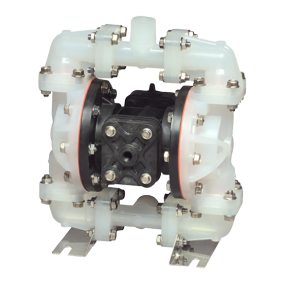
SERVICE & OPERATING MANUAL
Model S05 Non-Metallic Design Level 2
Table of Contents
Engineering Data and Temperature Limitations ........................................................1
Explanation of Pump Nomenclature .........................................................................2
Performance Curve...................................................................................................3
Dimensions ...............................................................................................................4
Metric Dimensions ....................................................................................................5
Principle of Pump Operation .....................................................................................6
Installation and Start-up ...........................................................................................6
Air Supply .................................................................................................................6
Air Valve Lubrication .................................................................................................6
Air Line Moisture .......................................................................................................6
Air Inlet and Priming .................................................................................................6
Between Uses ..........................................................................................................6
Installation Guide ......................................................................................................7
Troubleshooting .......................................................................................................8
Warranty ...................................................................................................................8
Important Safety Information ....................................................................................9
Material Codes .......................................................................................................10
Composite Repair Parts Drawing ...........................................................................12
Overlay Option Drawing, Muffler Option Drawing ...................................................12
Available Service and Conversion Kits ...................................................................12
Composite Repair Parts List ...................................................................................13
Air Valve Assembly Drawing and Parts List ...........................................................14
Air Valve Assembly Servicing .................................................................................15
Air Valve with Stroke Indicator Assembly Drawing and Parts List ...........................16
Air Valve with Stroke Indicator Assembly Servicing ................................................17
Pilot Valve Servicing, Assembly Drawing, and Parts List ........................................18
WARREN RUPP , INC. • A Unit of IDEX Corporation • P .O.Box 1568, Mansfield, Ohio 44901-1568 USA • Telephone (419) 524-8388 • Fax (419) 522-7867 • www.warrenrupp.com
s05nmdl2sm-REV1107
II 2GD T5
U.S. Patent #
400,210; 5,996,627;
6,241,487
Solenoid Shifted Air Valve Drawing ........................................................................19
Solenoid Shifted Air Valve Parts List ......................................................................19
Solenoid Shifted Air Distribution Valve Option ........................................................20
Intermediate Assembly Drawing, Parts List and Servicing .....................................21
Check Valve Drawing and Servicing .......................................................................22
Diaphragm Service Drawing, Non-Overlay .............................................................23
Diaphragm Service Drawing, with Overlay .............................................................23
Diaphragm Servicing ..............................................................................................24
Overlay Diaphragm Servicing ................................................................................24
Dual Port Option Drawing .......................................................................................25
Dual Porting Options ..............................................................................................26
Dual porting of both suction and discharge ends of the pump ...............................26
Single porting of the suction and dual porting of the pump discharge ...................26
Dual porting of the suction and single porting of the pump discharge ...................26
Single Port Suction Repair Parts List .....................................................................27
Single Port Discharge Repair Parts List .................................................................27
Dual Port Suction and Discharge Repair Parts List ................................................27
Pumping Hazardous Liquids ...................................................................................28
Converting the pump for piping the exhaust air ......................................................28
Exhaust Conversion Drawing .................................................................................28
Converted Exhaust Illustration ................................................................................28
Pulse Output Kit Drawing .......................................................................................29
Pulse Output Kit Option ..........................................................................................29
Muffler Options .......................................................................................................30
Grounding The Pump .............................................................................................31
CE Declaration of Conformity .................................................................................32
CE
©Copyright 2007 Warren Rupp, Inc. All rights reserved.
Advertisement
Table of Contents

Related Manuals for Warren rupp Sandpiper S05 Non-Metallic


Summary of Contents for Warren rupp Sandpiper S05 Non-Metallic
-
Page 1: Table Of Contents
CE Declaration of Conformity .................32 Pilot Valve Servicing, Assembly Drawing, and Parts List ........18 WARREN RUPP , INC. • A Unit of IDEX Corporation • P .O.Box 1568, Mansfield, Ohio 44901-1568 USA • Telephone (419) 524-8388 • Fax (419) 522-7867 • www.warrenrupp.com s05nmdl2sm-REV1107... -
Page 3: Engineering Data And Temperature Limitations
-10°F with highly polar solvents like acetone and MEK, ozone, chlorinated hydrocarbons and nitro hyrdrocarbons. 88°C -23°C For specific applications, always consult the Warren Rupp “Chemical Resistance Chart” SANDPIPER pumps are designed to be powered only by compressed air. ®... -
Page 4: Explanation Of Pump Nomenclature
Explanation of Pump Nomenclature S05 Non-Metallic · Design level 2· Ball Valve Check Diaphragm/ Check Non-Wetted Shipping Model Pump Pump Valve Design Wetted Check Valve Valve Material Porting Pump Pump Weight Brand Size Type level Material Materials Seat Options Options Style Options Options lbs. -
Page 5: Performance Curve
Performance Curve, S05 Non-Metallic Design level 2 MODEL S05 Non-Metallic Performance Curve Performance based on the following: elastomer fitted pump, flooded suction, water at ambient conditions. The use of other materials and varying hydraulic conditions may result in deviations in excess of 5%. 2 (3.5) 4 (7) 6 (10) -
Page 6: Dimensions
Dimensions: S05 Non-Metallic Dimensions in Inches Dimensional tolerance: ± " *Discharge Port 1/2" NPT (Internal) 1" NPT (External) Manifold Can Rotate ±90° From Vertical Centerline Standard Encapsulated Muffler: Air Inlet 1/4" NPT 3/8" NPT Exhaust Port For Optional Muffler Styles or Piping Exhaust Air In Submerged Applications. -
Page 7: Metric Dimensions
Metric Dimensions: S05 Non-Metallic Dimensions in millimeters Dimensional tolerance: ±3mm * Discharge Port 1/2" NPT (Internal) 44mm 1" NPT (External) Manifold Can Rotate ± 90° From Vertical Centerline. Standard Encapsulated Muffler: Air Inlet 1/4" NPT 3/8" NPT Exhaust Port For Optional Muffler Styles or Piping Exhaust Air In Submerged Applications. -
Page 8: Principle Of Pump Operation
(available at restart.) In freezing temperatures at discharge heads over 200 feet (61 the suction line diameter. from Warren Rupp) set to deliver one the pump must be completely drained meters) of water. For installations of rigid piping, drop of SAE 10 non-detergent oil for between uses in all cases. -
Page 9: Installation Guide
INSTALLATION GUIDE Top Discharge Ball Valve Unit Available from Surge Warren Rupp Dampener Limited to DA05 Surge Dampener 100 psi 020-049-000 Filter/Regulator Air Dryer CAUTION The air exhaust should be piped to an area for safe disposition of the product being pumped, in the event of a diaphragm failure. -
Page 10: Troubleshooting
Most connectors and a Warren Rupp seating. Replace if necessary. Refer local Warren Rupp Distributor or factory diaphragm pumps are designed for 1:1 Tranquilizer ® Surge Suppressor. -
Page 11: Important Safety Information
RECyClINg IMPORTANT SAfETy WARNINg INfORMATION Many components of SANDPIPER ® Take action to prevent static AODD pumps are made of recyclable sparking. Fire or explosion materials (see chart on page 10 for can result, especially when handling flammable liquids. material specifications). We encourage The pump, piping, valves, pump users to recycle worn out parts IMPORTANT... -
Page 12: Material Codes
Philthane (Tuftane) PTFE (Bronze and moly filled) Warren Rupp, SANDPIPER, Portapump, Oil Impregnated Carboxylated Nitrile Filled PTFE Tranquilizers and SludgeMaser are registered Die Cast Zinc Fluorinated Nitrile Blue Gylon tradenames of Warren Rupp, Inc. s05nmdl2sm-REV1107 Model S05 Non-Metallic Page 10... - Page 13 s05nmdl2sm-REV1107 Model S05 Non-Metallic Page 11...
-
Page 14: Composite Repair Parts Drawing
Composite Repair Parts Drawing ILLUSTRATION SHOWS DIRECTION OF DIAPHRAGMS Available Service And Conversion kits 476-219-000 AIR END kIT Seals, O-ring, Gaskets, Retaining Rings, Air Valve Assembly and Pilot Valve Assembly 476-220-000 AIR END kIT (Air Valve with Stroke Indicator Pin) Seals, O-ring, Gaskets, Retaining Rings, Air Valve Assembly Pilot Valve Assembly 476-202-360... -
Page 15: Composite Repair Parts List
ATEX Compliant Composite Repair Parts list 286-095-360 Diaphragm 286-116-000 Diaphragm, One-Piece Item Part Number Description 286-096-600 Diaphragm, Overlay 031-166-000 Air Valve Assembly 312-106-520 Elbow, Suction 031-166-002 Air Valve Assembly (with PTFE Coated Hardware) 312-106-521 Elbow, Suction 031-166-003 Air Valve Assembly (with Conductive Polypropylene) 312-106-542 Elbow, Suction 031-167-000... -
Page 16: Air Valve Assembly Drawing And Parts List
Air Distribution Valve Assembly Drawing MAIN AIR VAlVE ASSEMBly PARTS lIST Item Part Number Description 031-166-000 Air Valve Assembly 095-106-551 Body, Air Valve 031-132-000 Sleeve and Spool Set 560-101-360 O-Ring 165-122-551 End Cap 560-026-360 O-Ring 675-062-115 End Cap Retainer 530-031-550 Muffler 165-109-551 Muffler Cap... -
Page 17: Air Valve Assembly Servicing
AIR DISTRIBUTION VAlVE Inspect the inner diameter of the Install the remaining end cap with IMPORTANT SERVICINg sleeve (part of item 1-B) for dir t, o-rings and retainer. To service the air valve first shut scratches, or other contaminants. Fasten the air valve assembly (item Read these instructions Remove the sleeve if needed and 1) and gasket (item 23) to the pump,... -
Page 18: Air Valve With Stroke Indicator Assembly Drawing And Parts List
Air Valve with Stroke Indicator Assembly Drawing, Parts list MAIN AIR VAlVE ASSEMBly PARTS lIST Item Part Number Description 031-167-000 Air Valve Assembly 095-106-559 Body, Air Valve 031-134-000 Sleeve and Spool Set 560-101-360 O-Ring 132.030.552 Bumper 165-123-147 End Cap 560-029-360 O-Ring 675-062-115 End Cap Retainer... -
Page 19: Air Valve With Stroke Indicator Assembly Servicing
AIR DISTRIBUTION VAlVE WITh Inspect the inner diameter of the Fasten the air valve assembly (item IMPORTANT S T RO k E I N D I C ATO R O P T I O N sleeve (part of item 1-B) for dirt, 1) and gasket (item 23) to the pump, SERVICINg scratches, or other contaminants. -
Page 20: Pilot Valve Servicing, Assembly Drawing, And Parts List
Pilot Valve Servicing, Assembly Drawing & Parts list PIlOT VAlVE ASSEMBly PARTS lIST ITEM PART NUMBER DESCRIPTION 095-091-000 Pilot Valve Assembly 095-087-551 Valve Body 755-051-000 Sleeve (With O-rings) 560-033-360 O-ring (Sleeve) 775-055-000 Spool (With O-rings) 560-023-360 O-ring (Spool) 675-037-080 Retaining Ring PIlOT VAlVE SERVICINg STEP #2: Disassembly of the pilot STEP #3: Re-assembly of the pilot... -
Page 21: Solenoid Shifted Air Valve Drawing
Solenoid Shifted Air Valve Drawing Note: Pumps equipped with Explosion-Proof Solenoid Coils are ATEX compliant. SOlENOID ShIfTED AIR VAlVE PARTS lIST (Includes all items used on Composite Repair Parts List except as shown) Item Part Number Description 114-023-551 Bracket, Intermediate 893-099-000 Solenoid Valve, NEMA4 219-001-000... -
Page 22: Solenoid Shifted Air Distribution Valve Option
SOlENOID ShIfTED AIR Wiring DISTRIBUTION VAlVE OPTION Solenoid Connector Diagram Warren Rupp’s solenoid shifted, air distribution valve option utilizes electrical 3rd Terminal for signals to precisely control your ground. Before wiring, remove SANDPIPER’s speed. The solenoid coil terminal block from... -
Page 23: Intermediate Assembly Drawing, Parts List And Servicing
Intermediate Assembly Drawing Intermediate Assembly Servicing ACTUATOR PlUNgER SERVICINg Step #3: Re-install the pilot valve To service the actuator plunger first assembly into the inter mediate shut off the compressed air supply, assembly. bleed the pressure from the pump, and Be careful to align the ends of disconnect the air supply line from the the stem between the plungers when... -
Page 24: Check Valve Drawing And Servicing
Check Ball Valve Drawing MODUlAR ChECk BAll VAlVE IMPORTANT SERVICINg Before servicing the check valves, Read these instructions first shut off the suction line and then completely, before in- the discharge line to the pump. Next, stallation and start-up. It is the responsibility of shut off the compressed air supply, the purchaser to retain bleed air pressure from the pump, and... -
Page 25: Diaphragm Service Drawing, Non-Overlay
Diaphragm Service Drawing Diaphragm Service Drawing, Diaphragm Service Drawing with Overlay with One-Piece Bonded (Use With TPE Diaphragms Only) (286-116-000 only) s05nmdl2sm-REV1107 Model S05 Non-Metallic Page 23... -
Page 26: Diaphragm Servicing
DIAPhRAgM SERVICINg 3/4" wrench or socket to remove the possible. Make sure the bumper (item 6) A small amount of grease may be To service the diaphragms first outer diaphragm plate (item 27) by is installed over the diaphragm rod. applied between the inner plate and the shut off the suction, then shut off the turning counterclockwise. -
Page 27: Dual Port Option Drawing
Dual Port Option Drawing 1" NPT or 1" BSP Tapered External ½" NPT or ½" BSP Tapered Internal Connection ½" NPT or ½" BSP Tapered Connection ½" NPT or ½" BSP Tapered Connection Illustration for Dual Port Suction and Single or Dual Port Discharge Illustration for Single Port Suction with Dual Port Discharge s05nmdl2sm-REV1107... -
Page 28: Dual Porting Options
DUAl PORTINg OPTIONS SINglE PORTINg Of ThE SUCTION IMPORTANT Several dual porting options are AND DUAl PORTINg Of ThE PUMP possible. The pump can be converted DISChARgE Read these instructions to a dual port arrangement on both To conver t the pump from the completely, before in- the suction and the discharge ends. -
Page 29: Single Port Suction Repair Parts List
SINglE PORT SUCTION REPAIR PARTS lIST 544-005-115 Nut, Flanged 5/16-18 Item Part Number Description 544-005-308 Nut, Flanged 5/16-18 171-063-115 Capscrew, Flanged 5/16-18 x 1.25 115-144-305 Bracket, Free Standing (replaces 115-140-115) 171-063-308 Capscrew, Flanged 5/16-18 x 1.25 115-144-306 Bracket, Free Standing (replaces 115-140-115) 312-112-520N Elbow, ½NPT (replaces 312-112-520) 171-068-115... -
Page 30: Pumping Hazardous Liquids
PUMPINg hAzARDOUS lIQUIDS IMPORTANT INSTAllATION NOTE: CONVERTED EXhAUST IllUSTRATION When a diaphragm fails, the pumped The manufacturer recommends PUMP INSTAllATION AREA liquid or fumes enter the air end of installing a flexible hose or connection SAfE AIR the pump. Fumes are exhausted into between the pump and any rigid EXhAUST DISPOSAl... -
Page 31: Pulse Output Kit Drawing
Pulse Output kit Drawing PUlSE OUTPUT kIT OPTION This pump can be fitted with a Pulse Output Kit. This converts the mechanical strokes of the pump to an electrical signal which interfaces with the Stroke Counter/ Batch Controller or user control devices such as a PLC. -
Page 32: Muffler Options
Optional Muffler Configurations, Drawing OPTION 0 530-031-550 Integral Muffler uses (1) Cap and (4) 706-027-115 Machine Screw to hold it in place. OPTION 1 530-024-000 Sound Dampening Muffler screws directly into the Air Valve body. This muffler is equipped with a porous plastic element. -
Page 33: Grounding The Pump
grounding The Pump To be fully groundable, the pumps must be ATEX Compliant. Refer to pump data sheet for ordering. One eyelet end is fastened to the pump hardware. This optional 8 foot long (244 centimeters) Ground Strap (920-025-000) is available for easy ground connection. The other end is installed to a true earth ground. -
Page 34: Ce Declaration Of Conformity
Declaration of Conformity Warren Rupp, Inc., 800 North Main Street, Mans eld, Ohio, certi es that Air-Operated Double Diaphragm Pumps Series: HDB, HDF, M Non-Metallic, S Non-Metallic, M Metallic, S Metallic, Containment Duty, Gas, UL, High Pressure, W, Submersible and Tranquilizers comply with the European Community Directive 98/37/EC, Safety of Machinery.
Need help?
Do you have a question about the Sandpiper S05 Non-Metallic and is the answer not in the manual?
Questions and answers