Advertisement
Quick Links
SERVICE & OPERATING MANUAL
Original Instructions
Certified Quality
Certified Quality
ISO 9001 Certified
ISO 14001 Certified
Warren Rupp, Inc.
A Unit of IDEX Corporation
800 N. Main St.,
Mansfield, Ohio 44902 USA
Telephone 419.524.8388
Fax 419.522.7867
SANDPIPERPUMP.COM
© Copyright 2017 Warren Rupp, Inc.
All rights reserved
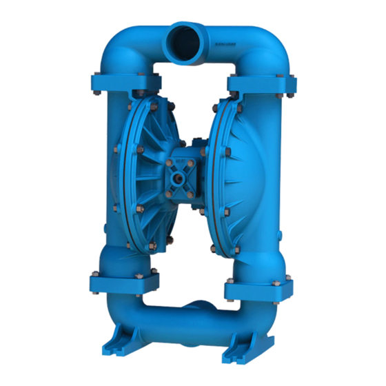
Model S30
Metallic
Design Level 1
OPTIMIZED PERFORMANCE
s a n d p i p e r p u m p. c o m
Advertisement

Subscribe to Our Youtube Channel
Related Manuals for Warren rupp SANDPIPER S30


Summary of Contents for Warren rupp SANDPIPER S30
- Page 1 A Unit of IDEX Corporation 800 N. Main St., Mansfield, Ohio 44902 USA Telephone 419.524.8388 Fax 419.522.7867 SANDPIPERPUMP.COM © Copyright 2017 Warren Rupp, Inc. All rights reserved s a n d p i p e r p u m p. c o m...
-
Page 2: Safety Information
The use of non-OEM replacement parts will void (or negate) agency certifications, including CE, ATEX, CSA, 3A and EC1935 compliance (Food Contact Materials). Warren Rupp, Inc. cannot ensure nor warrant non-OEM parts to meet the stringent requirements of the certifying agencies. - Page 3 Temperature Tables Table 1. Category 1 & Category 2 ATEX Rated Pumps Ambient Temperature Process Temperature Temperature Maximum Surface Tem- Range [°C] Range [°C] Class perature [°C] -20°C to +80°C T100°C -20°C to +108°C T135°C -20°C to +60°C -20°C to + 160°C T200°C -20°C to +177°C (225°C) T2 Per CSA standards ANSI LC6-2018 US & Canadian Technical Letter R14, G-Series Natural Gas Models are restricted to (-20°C to + 80°C) process temperature Table 2. Category 2 ATEX Rated Pumps Equipped with Pulse Output Kit or Integral Solenoid: Options Ambient Temperature Process Temperature...
- Page 4 Table of Contents SECTION 1: PUMP SPECIFICATIONS ....1 • Explanation of Nomenclature • Performance • Materials • Dimensional Drawings SECTION 2: INSTALLATION & OPERATION ...5 • Principle of Pump Operation • Recommended Installation Guide • Troubleshooting Guide SECTION 3: EXPLODED VIEW ......8 •...
- Page 5 Explanation of Pump Nomenclature Your Model #: S __ ____ ____ (fill in from pump nameplate) Pump Pump Check Design Wetted Diaphragm/ Check Valve Non-Wetted Porting Pump Pump Brand Size Valve Level Material Check Valve Seat Material Options Style Options Options Model #: Pump Brand...
- Page 6 Performance S30 METALLIC SUCTION/DISCHARGE PORT SIZE • 3" NPT or 3" BSP Tapered • 3" ANSI Flange or 3" DIN Flange MODEL S30 Metallic Performance Curve CAPACITY Performance based on the following: elastomer fitted pump, flooded suction, water at ambient conditions. The use of other materials and varying hydraulic conditions may result in deviations in excess of 5%.
- Page 7 Dimensional Drawings S30 Metallic, Threaded Ports Dimensional Tolerance:±1/8" [ ±3mm] FRONT VIEW 16.72 19.65 8.84 3.74 SIDE VIEW DISCHARGE PORT 3" NPT (3" BSPT) METALLIC MUFFLER DIMENSION 32.08 29.97 17.15 SUCTION PORT 3" NPT (3" BSPT) 2.35 3.74 2.46 7.23 11.76 14.46 15.75...
- Page 8 Dimensional Drawings S30 Metallic, Flanged Ports Dimensions in Inches. Dimensional Tolerance:±1/8" [ ±3mm] 16.72 15.75 FRONT VIEW SIDE VIEW 4.15 DISCHARGE PORT 3" RAISED FACE ANSI STYLE (150# LB) FLANGE OR 80 DIN (10 BAR) FLANGE METALLIC MUFFLER DIMENSION 35.66 31.75 18.93 SUCTION PORT...
- Page 9 Principle of Pump Operation Air-Operated Double Diaphragm (AODD) pumps are powered by compressed air or nitrogen. The main directional (air) control valve distributes ① compressed air to an air chamber, exerting uniform pressure over the inner surface of the diaphragm .
-
Page 10: Available Accessories
Recommended Installation Guide Available Accessories: 1. Surge Suppressor Unregulated Air 2. Filter/Regulator Supply to Surge Surge Suppressor Suppressor 3. Air Dryer Pressure Gauge Shut-Off Valve Pipe Connection Note: Surge Suppressor and (Style Optional) Piping must be supported after Flexible Connector Discharge the flexible connection Check Valve Shut-Off... -
Page 11: Troubleshooting Guide
Troubleshooting Guide Symptom: Potential Cause(s): Recommendation(s): Pump Cycles Once Deadhead (system pressure meets or exceeds air Increase the inlet air pressure to the pump. Pump is designed for 1:1 pressure ratio at zero flow. supply pressure). (Does not apply to high pressure 2:1 units). Air valve or intermediate gaskets installed incorrectly. - Page 12 Composite Repair Parts Drawing ITEM NO. PART NUMBER Torque: 90 In-Lbs. 031.XXX.XXX AIR VA (10 N-m) 050.XXX.XXX 070.006.170 Torque: 095.110.XXX 360 In-Lbs. (Alum, Stainless) (40 N-m) 114.024.XXX 500 In-Lbs. (Cast Iron) (56 N-m) 132.035.360 135.034.506 165.116.XXX 170.055.330 170.060.XXX 170.069.XXX 170.006.XXX 171.059.XXX 196.164.XXX 196.165.XXX...
- Page 13 Composite Repair Parts List Item Part Number Description Item Part Number Description 031.173.000 Air Valve Assembly (000 muffler) 518.144.156 Manifold, Discharge - NPT (w/ alum wetted) 031.173.001 Air Valve Assembly (000 muffler w/ SS hardware) 518.144.010 Manifold, Discharge - NPT (w/ cast iron wetted) 031.179.000 Air Valve Assembly (w/ cast iron or stainless center) 518.144.110...
- Page 14 Material Codes - The Last 3 Digits of Part Number 000..Assembly, sub-assembly; 364..EPDM Rubber • Delrin and Hytrel are registered tradenames of E.I. DuPont. and some purchased items Color coded: BLUE 010..Cast Iron 365..Neoprene Rubber • Nylatron is a registered tradename 015..Ductile Iron Color coded: GREEN of Polymer Corp.
- Page 15 Air Distribution Valve Assembly (Use with Aluminum Centers ONLY) Air Valve Assembly Parts List Air Distribution Valve Servicing Item Part Number Description See repair parts drawing, remove screws. 031-173-000 Air Valve Assembly Step 1: Remove Hex Head Cap Screws (1-F). 1-A 095-109-157 Body, Air Valve...
- Page 16 Air Distribution Valve Assembly Note: Cannot be used with Integral Muffler option 0. Air Valve Assembly Parts List (Use w/Aluminum centers only) Item Part Number Description 031-183-000 Air Valve Assembly Air Distribution Valve Servicing 1-A 095-109-157 Body, Air Valve 1-B 031-139-000 Sleeve and Spool Set See repair parts drawing, remove screws. 1-C 132-029-357 Bumper...
- Page 17 Air Valve with Stroke Indicator Assembly Note: Stroke Indicator is standard on Spill Containment models Air Valve Assembly Parts List Item Part Number Description 031-146-000 Air Valve Assembly 031-143-000 Sleeve and Spool Set w/Pins 095-119-559 Body, Air Valve 132-039-551 Bumper 165-096-559 Cap, Muffler 165-156-147 Cap, End Air Distribution Valve Servicing 530-028-550 Muffler See repair parts drawing, remove screws.
- Page 18 Pilot Valve Assembly Pilot Valve Servicing Pilot Valve Assembly Parts List With Pilot Valve removed from pump. Item Part Number Description Step 1: Remove snap ring (4-F). 095-110-000 Pilot Valve Assembly Step 2: Remove sleeve (4-B), inspect O-Rings (4-C), 4-A 095-095-157 Valve Body 4-B 755-052-000 Sleeve (With O-Rings)
- Page 19 Intermediate Assembly Drawing Intermediate Repair Parts List Intermediate Assembly Drawing Item Part Number Description Step 1: Remove plunger, actuator (29) from center of 114.024.157 Bracket, Intermediate intermediate pilot valve cavity. 114.024.010 Bracket, Intermediate Step 2: Remove Ring, Retaining (30), discard. 114.024.110 Bracket, Intermediate 135.034.506...
- Page 20 Diaphragm Service Drawing, with Overlay Diaphragm Service Drawing, Non-Overlay sandpiperpump • Model S30 Metallic s30mdl1sm-rev1218...
- Page 21 Diaphragm Servicing Step 1: With manifolds and outer chambers Step 8: On opposite side of pump, thread the removed, remove diaphragm assemblies from remaining assembly onto the diaphragm rod. Using a diaphragm rod. DO NOT use a pipe wrench or similar torque wrench, tighten the assembly to the diaphragm tool to remove assembly from rod.
- Page 22 Solenoid Shifted Air Valve Wiring Diagram 3rd Terminal for ground #2 Terminal #1 Terminal Neutral Power (Negative) (Positive) Solenoid Shifted Air Valve Parts List (Includes all items used on Composite Repair Parts List except as shown) Item Part Number Description 893-097-000 Solenoid Valve, NEMA4 1 219-001-000 Solenoid Coil, 24VDC 219-004-000 Solenoid Coil, 24VAC/12VDC 219-002-000 Solenoid Coil, 120VAC 219-003-000 Solenoid Coil, 240VAC 241-001-000 Connector, conduit 241-003-000...
-
Page 23: Declaration Of Conformity
Warren Rupp, Inc. (“Warren Rupp”) warrants to the original end-use purchaser that no product sold by Warren Rupp that bears a Warren Rupp brand shall fail under normal use and service due to a defect in material or workmanship within five years from the date of shipment from Warren Rupp’s factory. - Page 24 A Unit of IDEX Corporation 800 North Main Street Mansfield, OH 44902 USA Warren Rupp, Inc. declares that Air Operated Double Diaphragm Pumps (AODD) and Surge Suppressors listed below comply with the requirements of Directive 2014/34/EU and all applicable standards. Applicable Standards •...
Need help?
Do you have a question about the SANDPIPER S30 and is the answer not in the manual?
Questions and answers
I've completed a rebuilt for this s30 sandpiper pump and did a dry run test to check 0proper functionality. For some reason it won't pump consistently unless the pressure is set to 50 or more. I've tore back down made sure the cups seals and gaskets are installed correctly. In addition, I've made the sure the actuator pins aren't bent or missing. Do you have any insight on what the problem, might be?