Warren rupp Sandpiper S1F Service & Operating Manual
Metallic
Hide thumbs
Also See for Sandpiper S1F:
- Service & operating manual (15 pages) ,
- Service & operating manual (31 pages)
Advertisement
Quick Links
2.00
.13
SERVICE & OPERATING MANUAL
50.80
0.18
Original Instructions
4.18
106.29
8.37
212.71
Certified Quality
3.54
89.81
1.22
30.96
ISO 9001 Certified
ISO 14001 Certified
.41
10.32
6.73
171.07
5.00
Warren Rupp, Inc.
127.00
A Unit of IDEX Corporation
800 N. Main St.,
Mansfield, Ohio 44902 USA
Telephone 419.524.8388
Fax 419.522.7867
SANDPIPERPUMP.COM
© Copyright 2017 Warren Rupp, Inc.
All rights reserved
2.00
50.80
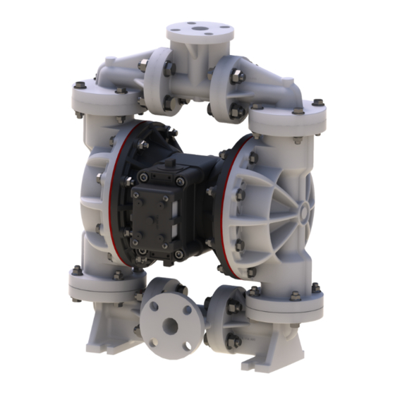
Model S1F
Metallic
4X
.38
MOUNTING HOLES
9.53
12.03
305.56
5.31
4.19
135
106.43
CALL TOLL FREE 877-742-2878 FOR SALES AND SUPPORT
9.09
230.80
1.63
41.28
5.00
127.00
s a n d p i p e r p u m p. c o m
81.76
Return to BurtProcess.com
3.93
DISCHARGE PORT
99.89
1" NPT
7.44
188.98
AIR INLET
1/2 NPT
6.39
162.31
Advertisement

Related Manuals for Warren rupp Sandpiper S1F


Summary of Contents for Warren rupp Sandpiper S1F
- Page 1 A Unit of IDEX Corporation 800 N. Main St., Mansfield, Ohio 44902 USA Telephone 419.524.8388 Fax 419.522.7867 SANDPIPERPUMP.COM © Copyright 2017 Warren Rupp, Inc. All rights reserved s a n d p i p e r p u m p. c o m...
- Page 2 The use of non-OEM replacement parts will void (or negate) agency certifications, including CE, ATEX, CSA, 3A and EC1935 compliance (Food Contact Materials). Warren Rupp, Inc. cannot ensure nor warrant non-OEM parts to meet the stringent requirements of the certifying agencies.
- Page 3 Temperature Tables Table 1. Category 1 & Category 2 ATEX Rated Pumps Ambient Temperature Process Temperature Temperature Maximum Surface Tem- Range [°C] Range [°C] Class perature [°C] -20°C to +80°C T100°C -20°C to +108°C T135°C -20°C to +60°C -20°C to + 160°C T200°C -20°C to +177°C (225°C) T2 Per CSA standards ANSI LC6-2018 US & Canadian Technical Letter R14, G-Series Natural Gas Models are restricted to (-20°C to + 80°C) process temperature Table 2. Category 2 ATEX Rated Pumps Equipped with Pulse Output Kit or Integral Solenoid: Options Ambient Temperature Process Temperature...
- Page 4 Table of Contents SECTION 1: PUMP SPECIFICATIONS ....1 • Explanation of Nomenclature • Performance • Materials • Dimensional Drawings SECTION 2: INSTALLATION & OPERATION ...5 • Principle of Pump Operation • Recommended Installation Guide • Troubleshooting Guide SECTION 3: EXPLODED VIEW ......8 •...
-
Page 5: Design Level
Explanation of Pump Nomenclature Your Model #: S __ ____ ____ (fill in from pump nameplate) Pump Pump Check Design Wetted Diaphragm/ Check Valve Non-Wetted Porting Pump Pump Brand Size Valve Level Material Check Valve Seat Material Options Style Options Options Model #: Pump Brand... - Page 6 Performance S1F METALLIC MODEL S1F Metallic Performance Curve SUCTION/DISCHARGE PORT SIZE Performance based on the following: elastomer fitted pump, flooded suction, water at ambient conditions. • 1" NPT (internal) The use of other materials and varying hydraulic conditions may result in deviations in excess of 5%. •...
-
Page 7: Suction Port 1" Npt
Dimensional Drawings S1F Metallic - NPT Dimensions in inches (mm dimensions in brackets). Dimensional Tolerance:±1/8" (± 3mm) The dimensions on this drawing are for reference only. A certified drawing can be requested if physical dimensions are needed. 10.25 9.09 260.35 10.25 230.80 5.13... -
Page 8: 171.07 Bottom View
Dimensional Drawings S1F Metallic - ANSI Flange Dimensions in inches (mm dimensions in brackets). Dimensional Tolerance:±1/8" (± 3mm) The dimensions on this drawing are for reference only. A certified drawing can be requested if physical dimensions are needed. 9.10 231.14 10.25 260.35 3.87... - Page 9 Principle of Pump Operation Air-Operated Double Diaphragm (AODD) pumps are powered by compressed air or nitrogen. The main directional (air) control valve distributes ① compressed air to an air chamber, exerting uniform pressure over the inner surface of the diaphragm .
- Page 10 Recommended Installation Guide Available Accessories: 1. Surge Suppressor Unregulated Air 2. Filter/Regulator Supply to Surge Surge Suppressor Suppressor 3. Air Dryer Pressure Gauge Shut-Off Valve Pipe Connection Note: Surge Suppressor and (Style Optional) Piping must be supported after Flexible Connector Discharge the flexible connection Check Valve Shut-Off...
- Page 11 Troubleshooting Guide Symptom: Potential Cause(s): Recommendation(s): Pump Cycles Once Deadhead (system pressure meets or exceeds air Increase the inlet air pressure to the pump. Pump is designed for 1:1 pressure ratio at zero flow. supply pressure). (Does not apply to high pressure 2:1 units). Air valve or intermediate gaskets installed incorrectly.
- Page 12 Composite Repair Parts Drawing Torque: 90 In-lbs (10 N-m) Torque: 90 In-lbs (10 N-m) OPTIONAL MUFFLER Torque: 350 In-lbs (39 N-m) Torque: 450 In-lbs (50 N-m) PTFE OPTIONAL OVERLAY Service & Repair Kits OPTIONAL METALLIC SEAT 476-228-000 Air End Kit (Aluminum Center) 476-194-356 Wet End Kit Seals, O-Ring, Gaskets, Retaining Rings, Air Valve...
- Page 13 Composite Repair Parts List Item Part Number Description Item Part Number Description 031.179.000 Air Valve Assembly 518.176.156 Manifold, Discharge (Cast Iron Centers Only) 518.176.156E Manifold, Discharge 1" 031.146.000 Air Valve Assembly (BSP Tapered) (Stroke Indicator) 518.176.156W Welded Raised Face 150# 031.147.000 Air Valve Assembly 1"...
- Page 14 Material Codes - The Last 3 Digits of Part Number 000..Assembly, sub-assembly; 364..EPDM Rubber • Delrin and Hytrel are registered tradenames of E.I. DuPont. and some purchased items Color coded: BLUE 010..Cast Iron 365..Neoprene Rubber • Nylatron is a registered tradename 015..Ductile Iron Color coded: GREEN of Polymer Corp.
- Page 15 Air Distribution Valve Assembly (Use With Aluminum Centers Only) Air Distribution Valve Servicing **Air Valve Assembly Parts List Item Part Number Description See repair parts drawing, remove screws. 031.173.000 Air Valve Assembly Step 1: Remove hex cap screws (1-F). 095.109.157 Body, Air Valve Step 2: Remove end cap (1-E) and bumper (1-C).
- Page 16 Air Distribution Valve Assembly Air Distribution Valve Servicing Air Valve Assembly Parts List (Use w/Aluminum center sections) See repair parts drawing, remove screws. Item Part Number Description Step 1: Remove hex cap screws (1-F). 031.183.000 Air Valve Assembly Step 2: Remove end cap (1-E) and bumper (1-C). 095.109.157 Body, Air Valve 031.139.000...
- Page 17 Air Distribution Valve Assembly (Use With Cast Iron Centers Only) Note: cannot be used with integral muffler Option 0. Air Distribution Valve Servicing Air Valve Assembly Parts List Item Part Number Description See repair parts drawing, remove screws. 031.179.000 Gas Valve Assembly Step 1: Remove hex cap screws (1-F). 095.109.110 Valve Body Step 2: Remove end cap (1-E) and bumper (1-C).
- Page 18 Air Valve with Stroke Indicator Assembly Note: Stroke Indicator is standard on Spill Containment models Air Valve Assembly Parts List Item Part Number Description 031-146-000 Air Valve Assembly 031-143-000 Sleeve and Spool Set w/Pins 095-119-559 Body, Air Valve 132-039-551 Bumper 165-096-559 Cap, Muffler 165-156-147 Cap, End Air Distribution Valve Servicing 530-028-550 Muffler See repair parts drawing, remove screws.
- Page 19 Pilot Valve Assembly Pilot Valve Servicing Pilot Valve Assembly Parts List With Pilot Valve removed from pump. Item Part Number Description Step 1: Remove snap ring (4-F). 095.110.000 Pilot Valve Assembly Step 2: Remove sleeve (4-B), inspect O-Rings (4-C), 095.095.157 Valve Body 755.052.000 Sleeve (With O-Rings)
- Page 20 Intermediate Assembly Intermediate Assembly Drawing Intermediate Assembly Parts List Step 1: Remove plunger, actuator (25) from center of Item Part Number Description intermediate pilot valve cavity. 114.025.157 Intermediate 114.025.010 Intermediate Cast Iron Centers Step 2: Remove Ring, Retaining (26), discard. 135.036.506 Bushing, Plunger* Step 3: Remove bushing, plunger (7), inspect for wear...
- Page 21 Diaphragm Service Drawing, with Overlay Torque: 450 In-lbs (50 N-m) PTFE Diaphragm Service Drawing, Non-Overlay Torque: 350 In-lbs (39 N-m) for Santoprene and Elastomer diaphragms One-Piece Bonded *Diaphragm Service Drawing *Available For Field Conversion From Overlay To One-Piece Bonded Diaphragm Kits: Kit: 475.250.000 286.112.000...
- Page 22 Diaphragm Servicing Step 1: With manifolds and outer chambers Step 8: On opposite side of pump, thread the removed, remove diaphragm assemblies from remaining assembly onto the diaphragm rod. Using a diaphragm rod. DO NOT use a pipe wrench or similar torque wrench, tighten the assembly to the diaphragm tool to remove assembly from rod.
- Page 23 893.097.000 Solenoid Valve, NEMA4 Distribution Valve Option 219.001.000 Solenoid Coil, 24VDC Warren Rupp’s solenoid shifted, air distribution valve option utilizes electrical 219.004.000 Solenoid Coil, 24VAC/12VDC signals to precisely control your SANDPIPERs speed. The solenoid coil is 219.002.000 Solenoid Coil, 120VAC 219.003.000...
- Page 24 Warren Rupp, Inc. (“Warren Rupp”) warrants to the original end-use purchaser that no product sold by Warren Rupp that bears a Warren Rupp brand shall fail under normal use and service due to a defect in material or workmanship within five years from the date of shipment from Warren Rupp’s factory.
- Page 25 A Unit of IDEX Corporation 800 North Main Street Mansfield, OH 44902 USA Warren Rupp, Inc. declares that Air Operated Double Diaphragm Pumps (AODD) and Surge Suppressors listed below comply with the requirements of Directive 2014/34/EU and all applicable standards. Applicable Standards •...
Need help?
Do you have a question about the Sandpiper S1F and is the answer not in the manual?
Questions and answers