Table of Contents
Advertisement
Quick Links
SERVICE & OPERATING MANUAL
Original Instructions
Certified Quality
ISO 9001 Certified
ISO 14001 Certified
Warren Rupp, Inc.
®
A Unit of IDEX Corporation
800 N. Main St.,
Mansfield, Ohio 44902 USA
Telephone 419.524.8388
Fax 419.522.7867
SANDPIPERPUMP.COM
© Copyright 2017 Warren Rupp, Inc.
All rights reserved
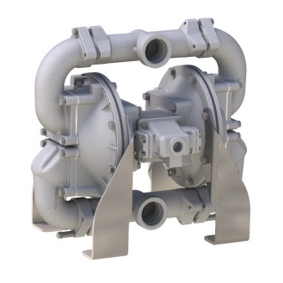
Model SPB20 BEAST
2" Non-Metallic Clog Resistant
Heavy Duty Flap Valve Pump
®
s a n d p i p e r p u m p. c o m
Advertisement
Table of Contents

Related Manuals for Warren rupp SANDPIPER BEAST SPB20


Summary of Contents for Warren rupp SANDPIPER BEAST SPB20
- Page 1 A Unit of IDEX Corporation 800 N. Main St., Mansfield, Ohio 44902 USA Telephone 419.524.8388 Fax 419.522.7867 SANDPIPERPUMP.COM © Copyright 2017 Warren Rupp, Inc. ® All rights reserved s a n d p i p e r p u m p. c o m...
- Page 2 The use of non-OEM replacement parts will void (or negate) agency certifications, including CE, ATEX, CSA, 3A and EC1935 compliance (Food Contact Materials). Warren Rupp, Inc. cannot ensure nor warrant non-OEM parts to meet the stringent requirements of the certifying agencies.
-
Page 3: Table Of Contents
Table of Contents SECTION 1: PUMP SPECIFICATIONS ....4 • Explanation of Nomenclature • Performance • Materials • Dimensional Drawings SECTION 2: INSTALLATION & OPERATION ...8 • Principle of Pump Operation • Recommended Installation Guide • Troubleshooting Guide SECTION 3: EXPLODED VIEW ......11 •... -
Page 4: Explanation Of Nomenclature
Explanation of Pump Nomenclature Your Model #: (fill in from pump nameplate) Pump Product Pump Check Wetted Non-Wetted Diaphragm Backup Seat Air Valve Exhaust Port Port Design Check Valve Material Brand Line Size Valve Type Material Material Diaphragm Material Material Valve Option Option... -
Page 5: Performance
Performance SPB20 BEAST NON - METALLIC MODEL HD20F Performance Curve FLAP VALVE Performance based on the following: elastomer fitted pump, flooded suction, water at ambient conditions. The use of other materials and varying hydraulic conditions may result in deviations in excess of 5%. SUCTION/DISCHARGE PORT SIZE •... -
Page 6: Dimensional Drawings
Dimensional Drawings SPB20 BEAST NON-METALLIC THREADED Dimensions in Inches [ ] in Millimeters. Dimensional tolerance: +/- 1/8" [ ] +/- 3mm Dim B 29.70 3.00 Dim A SUCTION PORT 2" NPT 2" BSPT 20.89 17.56 DISCHARGE PORT 9.78 2" FNPT 2"... - Page 7 Dimensional Drawings SPB20 BEAST NON-METALLIC FLANGED MANIFOLD Dimensions in Inches [ ] in Millimeters. Dimensional tolerance: +/- 1/8" [ ] +/- 3mm 29.20 2X 3.77 .78 X .87 SLOTTED UNIVERSAL FLANGE FITS ANSI 125# CONNECTION OR PN10 50MM DIN CONNECTION 19.03 22.36 11.25...
-
Page 8: Principle Of Pump Operation
Principle of Pump Operation Air-Operated Double Diaphragm (AODD) pumps are powered by compressed The pump primes as a result of the suction stroke. The suction stroke lowers (P3) air or nitrogen. the chamber pressure increasing the chamber volume. This results in (P4) a pressure differential necessary for atmospheric pressure to push the... -
Page 9: Recommended Installation Guide
Recommended Installation Guide Available Accessories: 1. Surge Suppressor 2. Filter/Regulator 3. Air Dryer 4. Lubricator Note: Surge Suppressor and Unregulated Air Piping, including air line, Supply to Surge must be supported after Suppressor the flexible connections. Pipe Connection Compound (Style Optional Gauge Shut-Off Flexible Connector... -
Page 10: Troubleshooting Guide
Troubleshooting Guide Symptom: Potential Cause(s): Recommendation(s): Pump Cycles Once Deadhead (system pressure meets or exceeds air Increase the inlet air pressure to the pump. Pump is designed for 1:1 pressure ratio at zero flow. supply pressure). (Does not apply to high pressure 2:1 units). Air valve or intermediate gaskets installed incorrectly. - Page 11 Composite Repair Parts Drawing Threaded OPTIONAL 90 ROTATION TORQUE SETTING TABLE in-lbs ANSI/DIN Flange Manifold Option 16.9 Item #14: use 242 Loctite or equivalent anaerobic adhesive during installation Item #16: use 242 Loctite or equivalent anaerobic adhesive during installation Item #47: if studs are replaced use 277 Loctite or equivalent anaerobic adhesive during installation sandpiperpump Model SPB20 Non-Metallic •...
-
Page 12: Composite Repair Parts List
Composite Repair Parts List Item Part Number Description Item Part Number Description 685.059.120 Rod, Diaphragm ** 031.140.000 Air Valve Assembly (Integral Muffler) 710.021.115 Screw, Pan Head 031.141.000 Air Valve Assembly (No Muffler) 720.004.360 Seal, U-cup 095.110.558 Pilot Valve Assembly 720.076.360 Seal, Clean Out Cap, Buna-N 114.024.551 Intermediate Assembly... - Page 13 Service & Repair Kits 476.353.000 Air End Kit Seals, O-rings, Gaskets, Retainer Rings, Aluminum Sleeve and spool set, pilot valve assembly 476.353.162 Air End Kit Seals, O-rings, Gaskets, Retainer Rings, Brass/Stainless Sleeve and spool set, pilot valve assembly 476.396.360 Wetted End Kit For Model For Model SPB20FPPB0SS000NR1/SPB20FPPB0SS000UR1 Buna-N Diaphragms, Hinge Pads, Seals, Wear Pads and Sealing Rings 476.396.363...
- Page 14 Material Codes - The Last 3 Digits of Part Number 000..Assembly, sub-assembly; 364..EPDM Rubber • Delrin and Hytrel are registered tradenames of E.I. DuPont. and some purchased items Color coded: BLUE 010..Cast Iron 365..Neoprene Rubber • Nylatron is a registered tradename 015..Ductile Iron Color coded: GREEN of Polymer Corp.
- Page 15 Air Distribution Valve Assembly Air Distribution Valve Servicing See repair parts drawing, remove screws. Step 1: Remove air valve from pump (1). Step 2: Remove retainer (1-E). Step 3: Remove end caps (1-C). Step 4: Remove spool part of (1-A) Inspect for wear or damage. Step 5: Press sleeve part of (1-A) from body (1-B) Inspect for wear or damage.
- Page 16 Air Valve with Stroke Indicator Assembly Note: Stroke Indicator is standard on Spill Containment models Air Distribution Valve Servicing See repair parts drawing, remove screws. Step 1: air valve from pump (1). Step 2: Remove retainer (1-E). Step 3: end caps (1-C) & bumpers (1-E) inspect o-rings 1-G. Step 4: Remove spool part of (1-A) Inspect for wear or damage.
- Page 17 Pilot Valve Assembly Pilot Valve Servicing Pilot Valve Assembly Parts List With Pilot Valve removed from pump. Item Part Number Description Step 1: Remove snap ring (2-F). 095-110-558 Pilot Valve Assembly Step 2: Remove sleeve (2-B), inspect O-Rings (2-C), 095-095-558 Valve Body replace if required.
- Page 18 Intermediate Assembly Intermediate Assembly Drawing Step 1: Remove plunger, actuator (36) from center of intermediate pilot valve cavity. Step 2: Remove ring, retaining (38), discard. Step 3: Remove bushing, plunger (7), inspect for wear and replace if necessary with genuine parts. Step 4: Remove O-ring (30), inspect for wear and replace if necessary with genuine parts.
- Page 19 Diaphragm Service Drawing, Non-Overlay Torque: 480 in-lbs. sandpiperpump Model SPB20 Non-Metallic • spb20fnmdl1sm-rev0422...
- Page 20 Diaphragm Servicing Step 1: With manifolds and outer chambers Step 7: Install diaphragm rod assembly removed, remove diaphragm assemblies from into pump and secure by installing the outer diaphragm rod. DO NOT use a pipe wrench or similar chamber in place and tightening the capscrews. tool to remove assembly from rod.
- Page 21 Warren Rupp, Inc. (“Warren Rupp”) warrants to the original end-use purchaser that no product sold by Warren Rupp that bears a Warren Rupp brand shall fail under normal use and service due to a defect in material or workmanship within five years from the date of shipment from Warren Rupp’s factory.
Need help?
Do you have a question about the SANDPIPER BEAST SPB20 and is the answer not in the manual?
Questions and answers