ADDER ADDERLink INFINITY 3000 User Manual
Hide thumbs
Also See for ADDERLink INFINITY 3000:
- Quick start manual (2 pages) ,
- Quick start (2 pages)

Related Manuals for ADDER ADDERLink INFINITY 3000


Summary of Contents for ADDER ADDERLink INFINITY 3000
- Page 1 ADDERLink INFINITY 3000 ™ User Guide Experts in KVM Extension Connectivity Solutions Solutions...
-
Page 2: Table Of Contents
Contents Introduction Configuration Welcome ........................2 ALIF3000 configuration ..................13 Gigabit connections ..................2 The recessed power button ..............13 Features ......................2 Performing a manual factory reset ............13 Technical Specifications .................3 Creating an RDP session ..................14 ALIF3000 unit features ..................4 Operation Supplied items .......................5 OLED screen .......................16 Optional extras .....................6 Front panel indications ..................17... -
Page 3: Welcome
• Pixel-perfect picture quality, wide ranging ADDERLink INFINITY family of • Multiple 1Gb Ethernet links, advanced extenders. The ALIF3000 receiver has • Adder’s USB True Emulation for fast USB 2.0 switching, been created to address the growing requirement ALIF3000 • Bi-directional analog audio, to connect users to both physical and virtual machines. -
Page 4: Technical Specifications
Technical Specifications Operating/storage conditions Operating temperature: 0 to 40ºC / 32 to 104ºF 6 ports of USB2.0 with USB True Emulation to support keyboard, mouse and touch. Storage temperature: 0 to 40ºC / 32 to 104ºF Max video resolution Storage and operating relative humidity: 10 to 90% non-condensing Supports 1x 2560x1600 up to maximum refresh rates of 60Hz or 2x 1920x1200 Altitude:... -
Page 5: Alif3000 Unit Features
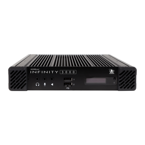
ALIF3000 UNIT FEATURES The ALIF3000 units are housed within durable, vented enclosures with connectors situated on the front and rear panels. The smart front faces also feature an OLED information screen with control button (to scroll through the various informational pages) and also a status indicator. Front AdderLink 3 0 0 0... -
Page 6: Supplied Items
SUPPLIED ITEMS ALIF3000 package Power adapter with locking connector and country-specific power cord A dd er Li ALIF3000 RX unit Information wallet 1GbE copper SFP module containing: Four self-adhesive rubber feet Quick start guide Safety document... -
Page 7: Optional Extras
OPTIONAL EXTRAS 1GbE single mode fiber SFP module Part number: SFP-SM-LC Please refer to the table in Appendix F Rack mount blanking plate information about fiber modules and cables. Part number: RMK12-BP 1GbE multi mode fiber SFP module Part number: SFP-MM-LC Dual unit 19”... -
Page 8: Installation
Installation CONNECTIONS MOUNTING Installation involves linking the ALIF3000 unit to networks and your peripherals Please see Appendix F for details about mounting options for ALIF units. (collectively known as the Console): IMPORTANT: When mounting the ALIF units (and their power adapters), ensure that the vents are not obscured and that there is sufficient airflow. -
Page 9: Video Displays
Video displays Audio VIDEO VIDEO DISPLAYS The ALIF3000 unit supports two video displays, The ALIF3000 unit can support a microphone DISPLAYS KVM & VM KVM & VM AUDIO AUDIO each up to 1920x1200 or a single display at NETWORK as well as speakers and/or headphones. DEVICE NETWORK DEVICE... -
Page 10: Usb Devices
USB devices VIDEO The ALIF3000 unit has six USB ports (two on the front panel and four on the rear) to DISPLAYS KVM & VM AUDIO which peripherals may be connected. NETWORK DEVICE To connect more than six peripherals, one or more USB hubs may be used. The total current that may be drawn from the USB ports is 1.2A, which should be sufficient for ALIF3000 RX a keyboard, mouse (no more than 100mA each) and any two other devices (500mA... -
Page 11: Power In
Power in VIDEO A power adapter is supplied with a country- DISPLAYS KVM & VM AUDIO specific power cord. The power adapter uses NETWORK DEVICE a locking-type plug to help prevent accidental disconnection; please follow the instructions ALIF3000 RX shown on the right when disconnecting a power adapter. -
Page 12: Kvm & Vm Network Links
KVM & VM network links VIDEO DISPLAYS Two SFP ports are located on the rear panel to allow fiber or copper links to separate KVM & VM AUDIO networks, according to the type of modules that are inserted. NETWORK DEVICE ALIF3000 RX To create fiber links Note: Units shipped before... -
Page 13: Vm-Only Network Link
VM-only network link VIDEO An RJ45 network socket is located on the rear panel to allow (up to) a 1Gb DISPLAYS KVM & VM AUDIO CATx copper link to a network. NETWORK DEVICE Note: This port is not supported by AIM and the ALIF3000 is not discoverable by AIM through this port. -
Page 14: Configuration
Press the button next to the OLED screen again. • The ADDERLink INFINITY Manager user guide (available from adder.com) for details • Continue with the factory reset: Use a long narrow about AIM configuration. -
Page 15: Creating An Rdp Session
CREATING AN RDP SESSION To create an RDP session 1 Within the AIM Manager’s network interface, navigate to the Transmitters page. This section details the steps required to configure a typical RDP session within ADDERLink INFINITY Manager (AIM). This diagram shows a typical connection layout: 2 At the top of the page, click on Add VDI. - Page 16 8 Click for the new channel entry to add users who will be granted access to it: 10 Click on first to enter the user credentials: 11 Enter the Username and Password required to access the RDP host. • Note: Do not use the # or “ characters or spaces within passwords. 12 Click Save.
-
Page 17: Operation
Operation In operation, many ALIF3000 installations require no intervention once configured. The Note: When first powered on and booting up, the indicators and screen unit takes care of all connection control behind the scenes so that you can continue to of the ALIF3000 unit will not respond for roughly 40 seconds. -
Page 18: Front Panel Indications
FRONT PANEL INDICATIONS The front panel of each ALIF3000 unit features a single indicator capable of producing numerous color and flash patterns to provide a useful guide to operation as well as an OLED information screen. Indicator color and flash patterns The single front panel indicator uses varying color and flashing patterns to signal key status: No power. -
Page 19: Further Information
• If the lithium battery needs to be changed, you must return the product to your nearest Adder dealer. The battery must be replaced by an authorized Adder dealer. • Once the product has come to the end of its useful life, the lithium battery must be removed as part of the decommissioning process and recycled in strict accordance with the regulations stipulated by your local authority. -
Page 20: Appendix A - Configuration Page
Remote Support the small button on the front panel next to the IP Address 2 The ALIF3000 remote support feature allows Adder technical support to connect via a ––––––––––––––– OLED screen to reveal the value for IP Address 1 or 10.0.20.37... -
Page 21: Appendix B - Tips For Success When Networking Alif Units
APPENDIX B - Tips for success when networking ALIF units Creating an efficient network layout ALIF units use multiple strategies to minimize the amount of data that they send across networks. However, data overheads can be quite high, particularly when very Network layout is vital. - Page 22 Configuring the switches and devices The layout is vital but so too is the configuration: • Enable IGMP Snooping on all L2 switches. • Ensure that IGMP Fast-Leave is enabled on all switches with ALIF units connected directly to them. •...
-
Page 23: Appendix C - Troubleshooting
APPENDIX C - Troubleshooting Problem: The video image of the ALIF receiver shows horizontal lines across Remedies: the screen. • Ensure that IGMP snooping is enabled on all switches within the subnet. This issue is known as Blinding because the resulting video image looks as though you’re •... - Page 24 Problem: The audio output of the ALIF receiver sounds like a scratched re- cord. This issue is called Audio crackle and is a symptom of the same problem that produces blinding (see previous page). The issue is related to missing data packets. Remedies: As per blinding discussed previously.
-
Page 25: Appendix D - Glossary
APPENDIX D - Glossary Internet Group Management Protocol IGMP Snooping Jumbo frames (Jumbo packets) Where an ALIF transmitter is required to stream video to The IGMP messages are effective but only operate at Since its commercial introduction in 1980, the Ethernet two or more receivers, multicasting is the method used. - Page 26 Spanning Tree Protocol (STP) Forwarding modes Layer 2 and Layer 3: The OSI model In order to build a robust network, it is necessary In essence, the job of a layer 2 switch is to transfer as When discussing network switches, the terms Layer 2 and to include certain levels of redundancy within the fast as possible, data packets arriving at one port out to Layer 3 are very often used.
- Page 27 In simplified terms, the wrapper that is added at Layer 2 (by the sending system) includes the physical address of the intended recipient system, i.e. the unique MAC address (for example, 09:f8:33:d7:66:12) that is assigned to every networking device at manufacture. Deciphering recipients at this level is more straightforward than at Layer 3, where the address of the recipient is represented by a logical IP address (e.g.
-
Page 28: Appendix E - Fiber/Copper Modules And Cables
To suit your installation layout, fiber and copper modules are available for the ALIF3000 units to support various fiber optic and CATx cables. The specifications for all are summarized in this table: Name Fiber size Type Coding Distance Adder part number for SFP Normal Suggested print 1Gbps module applications nomenclature (62.5/125) -
Page 29: Appendix F - Using The Optional Alif3000 Rack Shelf
APPENDIX F - Using the optional ALIF3000 rack shelf 1 Install the empty ALIF3000 rack mount tray into your 19” rack frame and fully IMPORTANT: When mounting the ALIF units (and their secure it. power adapters), ensure that the vents are not obscured 2 Place an ALIF3000 unit into each side of the rack mount tray so that their rear and that there is sufficient airflow. -
Page 30: Appendix G - Open Source Licenses
This product includes binaries that are derived from the open source community by The software included in this product contains copyrighted software that is licensed Adder under the GNU General Public License v2. Please follow the link below to view under the GNU General Public License (GPL). You may obtain the complete... - Page 31 © 2020 Adder Technology Limited All trademarks are acknowledged. www.ctxd.com Documentation by: Part No. MAN-ALIF3000-ADDER • Release 1.2...
-
Page 32: Index
Index Adaptive 25 Identify unit 19 Network layout 20 Serial Number 16 AIM 14 IGMP 24 Network links 11 SFP ports 11 Audio 8 fast-leave 24 KVM & VM 11 Snooping 24 querier 24 VM-only 12 Software version 16 snooping 24 Network switch Spanning Tree Protocol 25 Configuration...
Need help?
Do you have a question about the ADDERLink INFINITY 3000 and is the answer not in the manual?
Questions and answers