
Related Manuals for ADDER AdderLink Infinity 100T


Summary of Contents for ADDER AdderLink Infinity 100T
- Page 1 AdderLink Infinity 100T User Guide Experts in KVM Extension Connectivity Solutions Solutions...
-
Page 2: Table Of Contents
Contents Introduction Operation Welcome ........................2 Status indicators ....................10 Supplied items .......................3 Resetting.......................10 Optional extras .....................3 Further information Installation Getting assistance ....................11 Connections ......................4 Appendix A - Configuration pages ..............12 Video link ......................5 Appendix B - Dimensions ................19 Network link ....................5 Appendix C - Tips for success when networking ALIF units ....20 USB and power connections ...............6 Appendix D - Troubleshooting ................22... -
Page 3: Welcome
Introduction WELCOME ALIF and A.I.M. Where multiple ALIF units are used on a network, we have developed the AdderLink Thank you for choosing the AdderLink Infinity (aka ALIF) family of high capacity digital extenders/switches. By encoding high quality DVI video, digital audio and USB data into Infinity Management (A.I.M.) server to allow comprehensive and secure central control of all transmitters, receivers and users. -
Page 4: Supplied Items
SUPPLIED ITEMS OPTIONAL EXTRAS 12.5W power adapter Part number: PSU-IEC-5VDC-2.5A ALIF100T unit Country-specific power cords CAB-IEC-AUS (Australia) CAB-IEC-EURO (Europe) CAB-IEC-UK (United Kingdom) CAB-IEC-USA (United States) Information wallet containing: Four self-adhesive rubber feet Quick start guide Safety document... -
Page 5: Installation
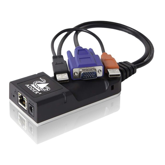
Installation CONNECTIONS Installation involves linking the ALIF100T unit to various ports on the host computer, while the ALIF RX unit is attached to your peripherals: Cable tie mounting slot Status indicators (page 10) DVI-D (or DisplayPort) connector input (page 5) Optional external power input... -
Page 6: Video Link
Video link Network link Each ALIF100T unit is supplied with either a DVI-D (single link) or a DisplayPort™ ALIF transmitters and receivers can either be connected directly to each other or via a video connector. Video signals at pixel clocks up to 165MHz (equivalent to a maximum high speed network. -
Page 7: Usb And Power Connections
USB and power connections The ALIF100T unit is designed to be as flexible as possible. It can either operate using Black USB plug provides an optional external power adapter (see page 3) or derive all of its power from its USB signals (plus power if two USB plugs. -
Page 8: Configuration
Configuration INITIAL CONFIGURATION Manual factory reset ALIF units are designed to be as flexible as possible and this principle extends also to A factory reset returns ALIF100T unit to its default configuration. You can perform their configuration. factory resets using the AdderLink Infinity browser-based configuration utility or by using this direct manual method. -
Page 9: Adderlink Infinity Browser-Based Configuration Utility
AdderLink Infinity browser-based configuration utility The browser-based configuration utility within all TX and RX units requires a network To access the browser-based configuration utility connection between the ALIF100T unit and a computer on the same network. The 1 Temporarily connect the ALIF100T unit and your computer, as discussed left. configuration utility allows you to perform many important functions. -
Page 10: Restoring A Backup Firmware Image
See left for details. To upgrade a single ALIF100T unit via the network link 1 Download the latest upgrade file from the Adder Technology website. Note: There are separate upgrade files for ALIF TX and RX units. -
Page 11: Operation
Operation In operation, many ALIF installations require no intervention once configured. The TX and RX units take care of all connection control behind the scenes so that you can continue to work unhindered. RESETTING STATUS INDICATORS The two top panel indicators on the ALIF100T unit provide a useful guide to operation: The recessed reset button provides a way to take control of the ALIF100T if normal operation is affected. -
Page 12: Further Information
- Dimensions • Online solutions and updates – www.adder.com/support • Appendix C - Tips for success when networking ALIF units Check the Support section of the adder.com website for the latest solutions and firmware updates. • Appendix D - Troubleshooting •... -
Page 13: Appendix A - Configuration Pages
APPENDIX A - Configuration pages This section covers the browser-based configuration utility for the ALIF100T unit. There are ten pages, titled as follows: • System Configuration • System Messages • Video Configuration • Statistics • USB Settings • Firmware Upgrade •... -
Page 14: System Configuration
System Configuration Unit Name Name details that you can alter to distinguish this unit from all others. The name entered here will be read by A.I.M. units (if used) for administration purposes. Unit Description Allows you to optionally add a description of ALIF100T unit, such as its location. Useful when many ALIF units are being used. - Page 15 Video Configuration Peak bandwidth limiter percentage The ALIF100T unit will employ a ‘best effort’ strategy in sending video and other data over the IP network. This means it will use as much of the available network bandwidth as necessary to achieve optimal data quality, although typically the ALIF100T unit will use considerably less than the maximum available.
- Page 16 USB Settings Enable Dummy Boot Keyboard When ticked, ALIF100T unit will report a virtual dummy boot keyboard to the attached PC to ensure that a keyboard is always reported when the PC boots up. The dummy boot keyboard uses one of the 13 USB endpoints, therefore if all 13 endpoints are required elsewhere for USB devices (or a KVM switch only supports two HID devices) then it can be disabled by deselecting this option.
- Page 17 Enable AIM Control Click this button to allow an A.I.M. (Adder Infinity Manager) box to take control of this TX. When the button is clicked, the ALIF100T unit will be rebooted to allow the A.I.M. box to discover and control it.
-
Page 18: Firmware Upgrade
Statistics Enable collection of bandwidth statistics ALIF units can record data transfer statistics from the System port and plot them on a graph for troubleshooting and optimization purposes. When you enable this option, you will first be presented with a pop up from which you can choose which aspects you would like to graph: Data throughput, various packet rates and/or frame rates. - Page 19 About About This page displays key information about the ALIF100T unit that may be requested by Adder Technical Support. To get here Connect your computer to the network port on the front panel. 2 Run a web browser and enter the IP address of the unit: http://169.254.1.33...
-
Page 20: Appendix B - Dimensions
APPENDIX B - Dimensions 0.2” (5mm) 0.98” (25mm) 4 x M3 holes 1.97” 2.2” (50mm) (56mm) 0.91” (23mm) 2.95” (75mm) 1.3” (33mm) 4.33” (110mm) -
Page 21: Appendix C - Tips For Success When Networking Alif Units
The Transmitter now joins its own multicast group so there is always a route from Infinity Implementation’ from www.adder.com/white-papers the querier to the transmitter which was previously missing in earlier firmware versions. • Use no more than two cascade levels. - Page 22 Configuring the switches and devices The layout is vital but so too is the configuration: • Enable IGMP Snooping on all L2 switches. • Ensure that IGMP Fast-Leave is enabled on all switches with ALIF units connected directly to them. •...
-
Page 23: Appendix D - Troubleshooting
APPENDIX D - Troubleshooting Problem: The video image of the ALIF receiver shows horizontal lines across Remedies: the screen. • Ensure that IGMP snooping is enabled on all switches within the subnet. This issue is known as Blinding because the resulting video image looks as though you’re •... - Page 24 • Apple Mac with Nvidia graphics random basis. Use the Adder utility for Mac’s – Contact technical support. You can easily tell whether portfast is enabled on a switch that is running STP: When • Apple Mac with ATI graphics you plug the link cable from a working ALIF unit into the switch port, check how long Enable the Magic Eye dither removal feature.
-
Page 25: Appendix E - Glossary
APPENDIX E - Glossary Internet Group Management Protocol IGMP Snooping Jumbo frames (Jumbo packets) Where an ALIF transmitter is required to stream video to The IGMP messages are effective but only operate at Since its commercial introduction in 1980, the Ethernet two or more receivers, multicasting is the method used. - Page 26 Spanning Tree Protocol (STP) Forwarding modes Layer 2 and Layer 3: The OSI model In order to build a robust network, it is necessary In essence, the job of a layer 2 switch is to transfer as When discussing network switches, the terms Layer 2 and to include certain levels of redundancy within the fast as possible, data packets arriving at one port out to Layer 3 are very often used.
- Page 27 In simplified terms, the wrapper that is added at Layer 2 (by the sending system) includes the physical address of the intended recipient system, i.e. the unique MAC address (for example, 09:f8:33:d7:66:12) that is assigned to every networking device at manufacture. Deciphering recipients at this level is more straightforward than at Layer 3, where the address of the recipient is represented by a logical IP address (e.g.
-
Page 28: Appendix F - Open Source Licenses
--------------- The software included in this product contains copyrighted software that is licensed under the GPL. You may obtain the complete Corresponding Source code from Adder /* ============================================================ for a period of three years after the last shipment of this product, which will be no ======== earlier than 2028, by contacting support@adder.com or writing to :... - Page 29 “This product includes software developed by the OpenSSL Project for use in the 1. Redistributions of source code must retain the copyright OpenSSL Toolkit (http://www.openssl.org/)” notice, this list of conditions and the following disclaimer. 2. Redistributions in binary form must reproduce the above copyright THIS SOFTWARE IS PROVIDED BY THE OpenSSL PROJECT ``AS IS’’...
- Page 30 DISCLAIMER * Redistributions of source code must retain the above copyright notice, this list of conditions and the following disclaimer. This software is provided ‘as is’ with no explicit or implied warranties in respect of its properties, including, but not limited to, correctness * Redistributions in binary form must reproduce the above and/or fitness for purpose.
- Page 31 * Redistributions in binary form must reproduce the above copyright THE SOFTWARE IS PROVIDED “AS IS”, WITHOUT WARRANTY OF ANY KIND, notice, this list of conditions and the following disclaimer in the EXPRESS OR IMPLIED, INCLUDING BUT NOT LIMITED TO THE WARRANTIES documentation and/or other materials provided with the OF MERCHANTABILITY, FITNESS FOR A PARTICULAR PURPOSE AND distribution.
- Page 32 License 1 — License for Open-Source Software Implementations of OCB (Jan 9, 2013) 1.6 “Open Source Software Implementation” means a Software Implementation in which the software implicating the Licensed Patents is Under this license, you are authorized to make, use, and Open Source Software.
- Page 33 The Institute of Electrical and Electronics Engineers and the American ---------------------------------------------------------------------------- National Standards Committee X3, on Information Processing Systems have given us permission to reprint portions of their documentation. - Module: freebsd-libc In the following statement, the phrase ``this text’’ refers to portions ---------------------------------------------------------------------------- of the system documentation.
- Page 34 Redistribution and use in source and binary forms, with or without modification, are permitted provided that the following conditions THIS SOFTWARE IS PROVIDED ``AS IS’’ AND WITHOUT ANY EXPRESS OR are met: IMPLIED WARRANTIES, INCLUDING, WITHOUT LIMITATION, THE IMPLIED 1. Redistributions of source code must retain the above copyright WARRANTIES OF MERCHANTABILITY AND FITNESS FOR A PARTICULAR notice, this list of conditions and the following disclaimer.
- Page 35 - aodv.h, Copyright (c) 2003 Bruce M. Simpson - atmuni31.h, Copyright (c) 1997 Yen Yen Lim and North Dakota State University # Internet Systems Consortium, Inc. - ieee802_11.h, Copyright (c) 2001 Fortress Technologies and Charlie Lenahan # 950 Charter Street - print-802_11.c, Copyright (c) 2001 Fortress Technologies and Charlie Lenahan # Redwood City, CA 94063 - print-aodv.c, Copyright (c) 2003 Bruce M.
- Page 36 10. [11]Nelson B Bolyard <nelson@bolyard.me> update and complete * Redistribution and use in source and binary forms, with or without * broadcast and crypto features in sntp * modification, are permitted provided that the following conditions * 11. [12]Jean-Francois Boudreault * are met: <Jean-Francois.Boudreault@viagenie.qc.ca>...
- Page 37 37. [40]David L. Mills <mills@udel.edu> Version 4 foundation, precision kernel; clock drivers: 1, 3, 4, 6, 7, 11, 13, 18, 19, 22, 36 38. [41]Wolfgang Moeller <moeller@gwdgv1.dnet.gwdg.de> VMS port 39. [42]Jeffrey Mogul <mogul@pa.dec.com> ntptrace utility 40. [43]Tom Moore <tmoore@fievel.daytonoh.ncr.com> i386 svr4 port 41.
-
Page 38: Waste Electrical And Electronic Equipment (Weee)
• No user serviceable parts within power adapter - do not dismantle. Adder will replace or repair it free of charge. No liability can be accepted for damage due • Plug the power adapter into a socket outlet close to the module that it is powering. -
Page 39: Radio Frequency Energy
RADIO FREQUENCY ENERGY A Category 5e (or better) twisted pair cable must be used to connect the units in order to maintain compliance with radio frequency energy emission regulations and ensure a suitably high level of immunity to electromagnetic disturbances. All cables used with this equipment must be shielded in order to maintain compliance with radio frequency energy emission regulations and ensure a suitably high level of immunity to electromagnetic disturbances. - Page 40 Web: www.adder.com Contact: www.adder.com/contact-details Support: www.adder.com/support © 2018 Adder Technology Limited All trademarks are acknowledged. www.ctxd.com Documentation by: Part No. MAN-ALIF100T-ADDER • Release 0.0c...
-
Page 41: Index
Index Adaptive 25 Factory reset 7 Layers 2 and 3 25 Querier 24 Troubleshooting 22 AFZ 14 Fast-Leave 24 Firmware upgrade 9 Magic Eye 14 Reset Upgrade firmware 9 Forwarding modes 25 Browser-based utility 8 Management port 13 manual 7 Fragment-free 25 TX settings 13 Reset button 4...
Need help?
Do you have a question about the AdderLink Infinity 100T and is the answer not in the manual?
Questions and answers