Table of Contents
Advertisement
Quick Links
DRV2511Q1EVM Haptic Solenoid Driver Evaluation Kit
ABSTRACT
The DRV2511-Q1 is an automotive qualified, high-efficiency, haptic solenoid driver that can provide up to
8 A of output current drive. The driver simplifies the design of solenoid control for haptic effects and
reduces the total solution size. This evaluation kit provides an easy way to test any solenoid with pre-
loaded or customizable waveforms to achieve different haptic effects. The EVM board includes the
following:
•
MSP430 MCU
•
On-board EEPROM
•
Selectable external analog inputs or pre-loaded/customizable PWM waveforms
•
EMC Filter
•
Small footprint (70 mm × 75 mm)
Evaluation Kit Contents:
•
DRV2511Q1EVM evaluation board
•
Firmware preloaded onto on-board EEPROM
•
Downloadable Haptics Control Console to control EVM
•
Micro USB cable
The following is required for programming and advanced configuration:
•
Code Composer Studio™ (CCS) or IAR Embedded Workbench IDE for MSP430
•
MSP430 LaunchPad (MSP-EXP430G2), or MSP430-FET430UIF hardware programming tool
•
DRV2511Q1EVM firmware available on DRV2511Q1EVM tool folder
SLOU448 – June 2016
Submit Documentation Feedback
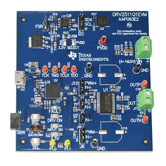
Figure 1. DRV2511Q1EVM Board
DRV2511Q1EVM Haptic Solenoid Driver Evaluation Kit
Copyright © 2016, Texas Instruments Incorporated
User's Guide
SLOU448 – June 2016
1
Advertisement
Table of Contents

Related Manuals for Texas Instruments DRV2511Q1EVM


Summary of Contents for Texas Instruments DRV2511Q1EVM
- Page 1 Code Composer Studio™ (CCS) or IAR Embedded Workbench IDE for MSP430 • MSP430 LaunchPad (MSP-EXP430G2), or MSP430-FET430UIF hardware programming tool • DRV2511Q1EVM firmware available on DRV2511Q1EVM tool folder Figure 1. DRV2511Q1EVM Board SLOU448 – June 2016 DRV2511Q1EVM Haptic Solenoid Driver Evaluation Kit Submit Documentation Feedback Copyright ©...
- Page 2 EU ECCN: EAR99 Technology may also require export or re-export license for shipping it in compliance with the applicable regulations of certain countries. DRV2511Q1EVM Haptic Solenoid Driver Evaluation Kit SLOU448 – June 2016 Submit Documentation Feedback Copyright © 2016, Texas Instruments Incorporated...
-
Page 3: Cautions And Warnings
Input type can be controlled using the Haptics Control Console for the DRV2511Q1EVM. The input is generated by an MSP430F5510 by using PWM signals. The EVM also has the option for the DRV2511-Q1 to receive inputs externally through the jumpers available on the board if necessary. -
Page 4: Powering The Board
Powering the Board To power the board, connect the DRV2511Q1EVM to an available USB port on your computer using the included Micro-USB cable. When USB power is applied, the TL760M33Q will take the 5-V supply voltage down to a regulated 3.3 V. The green 3.3-V LED will turn on and the MSP430 will be powered on. To power the DRV2511-Q1, external power must be supplied through header J5. -
Page 5: Connecting A Load
1. With the power supply off, connect either ± terminals on header J7 of the DRV2511Q1EVM to the solenoid. Polarity only matters if you are using a polarized solenoid. Typical solenoids are not polarized. - Page 6 Figure 5 below, the console contains a set of controls to manipulate the PWM Input Frequency, PWM Voltage Percentage, and duration of the PWM signal. DRV2511Q1EVM Haptic Solenoid Driver Evaluation Kit SLOU448 – June 2016 Submit Documentation Feedback Copyright © 2016, Texas Instruments Incorporated...
- Page 7 Overview of EVM www.ti.com Figure 5. DRV2511Q1EVM Haptics Control Console 2.4.1 PWM Input Frequency In the Standard Drive tab, the PWM input frequency can be changed using either a slider bar or by manually entering a frequency value. The minimum frequency is 1 Hz and the maximum frequency can be up to 65 kHz.
-
Page 8: Hardware Configuration
MSP430 PWM input disabled = LED Off 3.3 V MSP430 Powered On/Off Power Supply Overview The DRV2511Q1EVM relies on USB and an external power supply to operate completely. Refer to Table 3 for the power supply configurations. Table 3. Power Supply Configuration... -
Page 9: Measurement And Analysis
3.38 kHz. If the DRV2511Q1EVM filter is not used, TI recommends using a first-order, low-pass filter with a cutoff between 1 kHz and 3.5 kHz. - Page 10 Reference www.ti.com Reference This section includes the DRV2511Q1EVM schematic, PCB Layout, and bill of materials. Schematics 3.3V PWM+ PVDD TL760M33QKVURQ1 INPUT FILTER PWM- 5V-USB 10µF 0.1µF 10µF 0.1µF 3.3V 3.3V 100k TO DUT 3.3V STDBY 9.76k Green 3.3V 3.3V 1.2k...
- Page 11 These assemblies must be clean and free from flux and all contaminants. Use of no clean flux is not acceptable. Assembly Note These assemblies must comply with workmanship standards IPC-A-610 Class 2, unless otherwise specified. Figure 9. DRV2511-Q1 Schematic 3 SLOU448 – June 2016 DRV2511Q1EVM Haptic Solenoid Driver Evaluation Kit Submit Documentation Feedback Copyright © 2016, Texas Instruments Incorporated...
-
Page 12: Pcb Layout
Reference www.ti.com PCB Layout Figure 10. All Layers Figure 11. Top Layer DRV2511Q1EVM Haptic Solenoid Driver Evaluation Kit SLOU448 – June 2016 Submit Documentation Feedback Copyright © 2016, Texas Instruments Incorporated... - Page 13 Reference www.ti.com Figure 12. Signal Layer 1 Figure 13. Signal Layer 2 SLOU448 – June 2016 DRV2511Q1EVM Haptic Solenoid Driver Evaluation Kit Submit Documentation Feedback Copyright © 2016, Texas Instruments Incorporated...
- Page 14 Reference www.ti.com Figure 14. Bottom Layer DRV2511Q1EVM Haptic Solenoid Driver Evaluation Kit SLOU448 – June 2016 Submit Documentation Feedback Copyright © 2016, Texas Instruments Incorporated...
- Page 15 CAP, CERM, 18 pF, 50 V, ± 0402 GRM1555C1H180JA01D 5%, C0G/NP0, 0402 LED, Red, SMD Red LED, 1.6 mm × 0.8 mm × LTST-C190CKT 0.8 mm SLOU448 – June 2016 DRV2511Q1EVM Haptic Solenoid Driver Evaluation Kit Submit Documentation Feedback Copyright © 2016, Texas Instruments Incorporated...
- Page 16 9.76 k RES, 9.76 k, 1%, 0.063 W, 0402 CRCW04029K76FKED 0402 20.0 k RES, 20.0 k, 1%, 0.125 W, 0805 CRCW080520K0FKEA 0805 DRV2511Q1EVM Haptic Solenoid Driver Evaluation Kit SLOU448 – June 2016 Submit Documentation Feedback Copyright © 2016, Texas Instruments Incorporated...
- Page 17 10%, X7R, 0805 C14, C15 220 uF CAP, AL, 220 µF, 50 V, ± SMT Radial G EEE-FC1H221P 20%, 0.3 Ω, SMD SLOU448 – June 2016 DRV2511Q1EVM Haptic Solenoid Driver Evaluation Kit Submit Documentation Feedback Copyright © 2016, Texas Instruments Incorporated...
- Page 18 1.00 k RES, 1.00 k, 1%, 0.063 W, 0402 CRCW04021K00FKED 0402 100 k RES, 100 k, 0.1%, 0.063 W, 0603 CPF0603B100KE 0603 DRV2511Q1EVM Haptic Solenoid Driver Evaluation Kit SLOU448 – June 2016 Submit Documentation Feedback Copyright © 2016, Texas Instruments Incorporated...
-
Page 19: Important Notice
IMPORTANT NOTICE Texas Instruments Incorporated and its subsidiaries (TI) reserve the right to make corrections, enhancements, improvements and other changes to its semiconductor products and services per JESD46, latest issue, and to discontinue any product or service per JESD48, latest issue. - Page 20 Mouser Electronics Authorized Distributor Click to View Pricing, Inventory, Delivery & Lifecycle Information: Texas Instruments DRV2511Q1EVM...
Need help?
Do you have a question about the DRV2511Q1EVM and is the answer not in the manual?
Questions and answers