Table of Contents
Advertisement
Quick Links
bq24133EVM Stand-Alone Synchronous, Switch-Mode,
Battery-Charge Controller With Integrated N-MOSFETs
This user's guide describes the features and operation of the bq24133EVM Evaluation Module (EVM). The
EVM assists users in evaluating the bq24133 synchronous battery charger. The EVM is also called the
HPA715A. The manual includes the bq24133EVM bill of materials, board layout, and schematic.
..................................................................................................................
1
1.1
1.2
1.3
1.4
1.5
2
2.1
2.2
2.3
2.4
2.5
2.6
2.7
3
4
4.1
4.2
4.3
Schematic
1
2
...................................................................................................................
3
4
.................................................................................................................
5
6
7
8
1
I/O Description
2
Control and Key Parameters Settings
3
Recommended Operating Conditions
4
SLUU476 - December 2010
Submit Documentation Feedback
......................................................................................................
................................................................................................
......................................................................................................
...............................................................................................................
...........................................................................................................
................................................................................................................
...............................................................................................................
......................................................................................................
...........................................................................................................
...................................................................................................
...........................................................................................................
......................................................................................................
....................................................................................................
......................................................................................................
.........................................................................................................
..............................................................................................................
..............................................................................................................
...............................................................................................................
..........................................................................................................
.................................................................................................
...............................................................................................................
....................................................................................
....................................................................................
.............................................................................................................
bq24133EVM Stand-Alone Synchronous, Switch-Mode, Battery-Charge
© 2010, Texas Instruments Incorporated
and Power Path Selector
Contents
...........................................................................
...........................................................................
.......................................................................
List of Figures
......................................................................
List of Tables
Controller With Integrated N-MOSFETs and Power Path Selector
User's Guide
SLUU476 - December 2010
2
2
2
2
3
3
5
5
5
5
5
6
6
7
9
10
10
12
18
6
12
13
14
15
16
17
18
2
3
3
10
1
Advertisement
Table of Contents

Related Manuals for Texas Instruments bq24133EVM


Summary of Contents for Texas Instruments bq24133EVM
-
Page 1: Table Of Contents
Battery-Charge Controller With Integrated N-MOSFETs and Power Path Selector This user's guide describes the features and operation of the bq24133EVM Evaluation Module (EVM). The EVM assists users in evaluating the bq24133 synchronous battery charger. The EVM is also called the HPA715A. -
Page 2: Introduction
Connected to system J2–VBAT Connected to charger output J2–PGND Ground J2–TS_EXT Temperature qualification voltage Input bq24133EVM Stand-Alone Synchronous, Switch-Mode, Battery-Charge SLUU476 – December 2010 Controller With Integrated N-MOSFETs and Power Path Selector Submit Documentation Feedback © 2010, Texas Instruments Incorporated... -
Page 3: Control And Key Parameters Settings
For bq24133, the precharge current is set as 1/10 of the fast-charge rate set by ISET voltage, according to the formula SLUU476 – December 2010 bq24133EVM Stand-Alone Synchronous, Switch-Mode, Battery-Charge Controller With Integrated N-MOSFETs and Power Path Selector Submit Documentation Feedback... - Page 4 ACSET 20 R ´ The default setting on the EVM is 3 Adc for adapter current regulation. bq24133EVM Stand-Alone Synchronous, Switch-Mode, Battery-Charge SLUU476 – December 2010 Controller With Integrated N-MOSFETs and Power Path Selector Submit Documentation Feedback © 2010, Texas Instruments Incorporated...
-
Page 5: Test Summary
4. Precautions must be observed to avoid touching areas of the assembly that may get hot or present a shock hazard during testing. Quality 1. Test data can be made available on request from Texas Instruments. Safety Apparel 1. Electrostatic smock 2. -
Page 6: Equipment
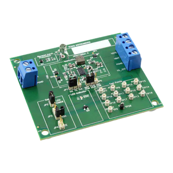
APPLICATION CIRCUIT LEDPWR /STAT TEST POINTS SETTINGS Figure 1. Original Test Setup for HPA715A (bq24133EVM) bq24133EVM Stand-Alone Synchronous, Switch-Mode, Battery-Charge SLUU476 – December 2010 Controller With Integrated N-MOSFETs and Power Path Selector Submit Documentation Feedback © 2010, Texas Instruments Incorporated... -
Page 7: Procedure
I(J2(VBAT)) decreases from 2 A while V(J2(VBAT)) becomes constant. Observe → I(J2(VBAT)) drops to zero when LOAD#2 current is less than 0.2 A. SLUU476 – December 2010 bq24133EVM Stand-Alone Synchronous, Switch-Mode, Battery-Charge Controller With Integrated N-MOSFETs and Power Path Selector Submit Documentation Feedback © 2010, Texas Instruments Incorporated... - Page 8 Observe → I(J2(VBAT)) decreases from 3 A to 0 A and I(J1(VIN)) keeps 3 A unchanged. 2.7.7 Test Complete Turn off the power supply, and remove all connections from the unit under test (UUT). bq24133EVM Stand-Alone Synchronous, Switch-Mode, Battery-Charge SLUU476 – December 2010 Controller With Integrated N-MOSFETs and Power Path Selector Submit Documentation Feedback...
-
Page 9: Pcb Layout Guideline
7. Decoupling capacitor(s) for the charger input must be placed close to SW and PGND. 8. Take the EVM layout for design reference. SLUU476 – December 2010 bq24133EVM Stand-Alone Synchronous, Switch-Mode, Battery-Charge Controller With Integrated N-MOSFETs and Power Path Selector Submit Documentation Feedback... -
Page 10: Bill Of Materials, Board Layout, And Schematic
Resistor, Chip, 1/16W, 5% 0603 30.1k Resistor, Chip, 1/16W, 1% 0603 3.01M Resistor, Chip, 1/16W, 1% 0603 bq24133EVM Stand-Alone Synchronous, Switch-Mode, Battery-Charge SLUU476 – December 2010 Controller With Integrated N-MOSFETs and Power Path Selector Submit Documentation Feedback © 2010, Texas Instruments Incorporated... - Page 11 5. Install label after final wash. Text shall be 8 pt font. Text shall be per Table 1. Table 1 Assembly Number Text HPA715-001 BQ24133EVM-715-5V HPA715-002 BQ24133EVM-715-15V SLUU476 – December 2010 bq24133EVM Stand-Alone Synchronous, Switch-Mode, Battery-Charge Controller With Integrated N-MOSFETs and Power Path Selector Submit Documentation Feedback © 2010, Texas Instruments Incorporated...
-
Page 12: Board Layout
Bill of Materials, Board Layout, and Schematic www.ti.com Board Layout Figure 2. Top Assembly bq24133EVM Stand-Alone Synchronous, Switch-Mode, Battery-Charge SLUU476 – December 2010 Controller With Integrated N-MOSFETs and Power Path Selector Submit Documentation Feedback © 2010, Texas Instruments Incorporated... -
Page 13: Top Layer
Bill of Materials, Board Layout, and Schematic www.ti.com Figure 3. Top Layer SLUU476 – December 2010 bq24133EVM Stand-Alone Synchronous, Switch-Mode, Battery-Charge Controller With Integrated N-MOSFETs and Power Path Selector Submit Documentation Feedback © 2010, Texas Instruments Incorporated... -
Page 14: Second Layer
Bill of Materials, Board Layout, and Schematic www.ti.com Figure 4. Second Layer bq24133EVM Stand-Alone Synchronous, Switch-Mode, Battery-Charge SLUU476 – December 2010 Controller With Integrated N-MOSFETs and Power Path Selector Submit Documentation Feedback © 2010, Texas Instruments Incorporated... -
Page 15: Third Layer
Bill of Materials, Board Layout, and Schematic www.ti.com Figure 5. Third Layer SLUU476 – December 2010 bq24133EVM Stand-Alone Synchronous, Switch-Mode, Battery-Charge Controller With Integrated N-MOSFETs and Power Path Selector Submit Documentation Feedback © 2010, Texas Instruments Incorporated... -
Page 16: Bottom Layer
Bill of Materials, Board Layout, and Schematic www.ti.com Figure 6. Bottom Layer bq24133EVM Stand-Alone Synchronous, Switch-Mode, Battery-Charge SLUU476 – December 2010 Controller With Integrated N-MOSFETs and Power Path Selector Submit Documentation Feedback © 2010, Texas Instruments Incorporated... -
Page 17: Bottom Assembly
Bill of Materials, Board Layout, and Schematic www.ti.com Figure 7. Bottom Assembly SLUU476 – December 2010 bq24133EVM Stand-Alone Synchronous, Switch-Mode, Battery-Charge Controller With Integrated N-MOSFETs and Power Path Selector Submit Documentation Feedback © 2010, Texas Instruments Incorporated... -
Page 18: Bq24133Evm Schematic
Bill of Materials, Board Layout, and Schematic www.ti.com Schematic Figure 8. bq24133EVM Schematic bq24133EVM Stand-Alone Synchronous, Switch-Mode, Battery-Charge SLUU476 – December 2010 Controller With Integrated N-MOSFETs and Power Path Selector Submit Documentation Feedback © 2010, Texas Instruments Incorporated... - Page 19 Evaluation Board/Kit Important Notice Texas Instruments (TI) provides the enclosed product(s) under the following conditions: This evaluation board/kit is intended for use for ENGINEERING DEVELOPMENT, DEMONSTRATION, OR EVALUATION PURPOSES ONLY and is not considered by TI to be a finished end-product fit for general consumer use. Persons handling the product(s) must have electronics training and observe good engineering practice standards.
- Page 20 TI products. TI’s provision of these resources does not expand or otherwise alter TI’s applicable warranties or warranty disclaimers for TI products. TI objects to and rejects any additional or different terms you may have proposed. IMPORTANT NOTICE Mailing Address: Texas Instruments, Post Office Box 655303, Dallas, Texas 75265 Copyright © 2021, Texas Instruments Incorporated...
Need help?
Do you have a question about the bq24133EVM and is the answer not in the manual?
Questions and answers