Alvarion BreezeNET B System Manual
Point-to-point wireless bridge release 3.1
Hide thumbs
Also See for BreezeNET B:
- Release note (6 pages) ,
- Brochure & specs (4 pages) ,
- System manual (232 pages)
Table of Contents
Advertisement
Quick Links
Advertisement
Table of Contents

Related Manuals for Alvarion BreezeNET B


Summary of Contents for Alvarion BreezeNET B
- Page 1 ® BreezeNET System Manual S/W Version 3.1 May 2005 P/N 214057...
- Page 3 Statement of Conditions The information contained in this manual is subject to change without notice. Alvarion Ltd. shall not be liable for errors contained herein or for incidental or consequential damages in connection with the furnishing, performance, or use of this manual or equipment supplied with it.
- Page 4 BEYOND THE RANGE OF THE INTENDED USE, OR BY ACCIDENT, FIRE, LIGHTNING OR OTHER HAZARD. Disclaimer (a) The Software is sold on an "AS IS" basis. Alvarion, its affiliates or its licensors MAKE NO WARRANTIES, WHATSOEVER, WHETHER EXPRESS OR IMPLIED, WITH RESPECT TO THE SOFTWARE AND THE ACCOMPANYING DOCUMENTATION.
-
Page 5: Limitation Of Liability
FCC Radio Frequency Interference Statement The BreezeNET B equipment has been tested and found to comply with the limits for a class B digital device, pursuant to part 15 of the FCC rules and to ETSI EN 301 489-1 rules. -
Page 6: R&Tte Compliance Statement
(when using external antenna) are grounded and suitable lightning protection devices are used so as to provide protection against voltage surges and static charges. In any event, Alvarion is not liable for any injury, damage or regulation violations associated with or caused by installation, grounding or lightning protection. -
Page 7: Important Notice
It could also void the user’s authority to operate the equipment. Some of the equipment provided by Alvarion and specified in this manual, is manufactured and warranted by third parties. All such equipment must be... - Page 8 Important Notice BreezeNET B System Manual viii...
- Page 9 BreezeNET B system, and for system administrators responsible for managing the system. This guide contains the following chapters and appendices: Chapter 1 – System description: Describes the BreezeNET B system and its components. Chapter 2 – Installation: Describes how to install the system components.
- Page 10 About This Manual Appendix F – Using the Feature License Web application: Describes how to use the Feature License web application for getting License Keys. BreezeNET B System Manual...
-
Page 11: Table Of Contents
Chapter 1 - System Description ...1 1.1 Introducing BreezeNET B... 2 1.2 System Components ... 4 1.3 Specifications ... 5 1.3.1 Radio specifications... 5 1.3.2 Data Communication ... 7 1.3.3 Configuration and Management ... 8 1.3.4 Physical and Electrical... 9 1.3.5 Standards Compliance, General... - Page 12 Appendix A - Software Version Loading Using TFTP ... 123 Appendix B - File Download and Upload Using TFTP ... 127 Appendix C - Using the Set Factory Defaults Utility ... 131 Appendix D - Preparing the Indoor to Outdoor Cable ... 133 BreezeNET B System Manual...
- Page 13 E.1.7 Service Parameters ... 145 E.1.8 Security Parameters ... 146 Appendix F - Using the Feature License Web Application ...147 F.1 The Feature License Web Application ... 148 F.1.1 Loading License Strings to Devices... 150 BreezeNET B System Manual Introducing BreezeNET B xiii...
- Page 15 Figures Figure 2-1: Threaded Holes/Grooves ... 18 Figure 2-2: 3" Pole Installation Using Special Brackets... 18 Figure 2-3: Bottom Panel of the Outdoor Unit (without the seal assembly)... 19 Figure 2-4: The Waterproof Seal ... 20 Figure 2-5: IDU PS 1036 Front Panel ... 22 Figure 2-6: IDU PS 1073 Front Panel ...
- Page 17 Tables Table 1-1: Frequency Bands... 2 Table 1-2: 5 GHz Band Detached Antennas ... 4 Table 1-3: Radio Specifications ... 5 Table 1-4: Data Communication ... 7 Table 1-5: Configuration and Management ... 8 Table 1-6: Mechanical Specifications ... 9 Table 1-7: Connectors...
- Page 18 Tables Table 4-7: VLAN Data Port Functionality - Trunk Link ...100 Table 4-8: VLAN Data Port Functionality - Hybrid Link ...100 Table 4-9: Recommended Maximum Modulation Level*...108 Table D-1: Cable Color Codes ...134 BreezeNET B System Manual xviii...
-
Page 19: Chapter 1 - System Description
Chapter 1 - System Description In This Chapter: Introducing BreezeNET B, page 2 System Components, page 4 Specifications, page 5... -
Page 20: Introducing Breezenet B
40 MHz frequency channels. When using 40 MHz (instead of 20 MHz) the BreezeNET B is operating in the “Turbo Mode”. The use of this “Turbo Mode” increases the net throughput of the BreezeNET B link, especially for links that suffer from low net throughput due to challenging link budget conditions that result from very long link distances, RF absorbing terrain or non line of sight. - Page 21 BreezeNET B system components can be managed using standard management tools through SNMP agents that implement standard and proprietary MIBs for remote setting of operational modes and parameters. The BreezeCONFIG utility is an SNMP-based application designed to manage BreezeNET B system components and upgrade unit software versions.
-
Page 22: System Components
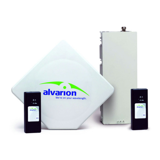
Chapter 1 - System Description System Components The BreezeNET B system includes a Base Unit (BU), typically installed at the main site, and a Remote Bridge (RB). Each unit is comprised of a desktop or wall-mountable Universal Indoor Unit (IDU) and an outdoor unit (ODU). The IDU provides the interface to the user’s equipment and is powered from the 110/220 VAC mains. -
Page 23: Specifications
Specifications 1.3.1 Radio specifications Item Frequency Operation Mode Channel Bandwidth Central Frequency Resolution ODU Integral Antenna Detached 5 GHz Antennas Antenna Port (D-model ODU) Max. Input Power (at antenna port) Maximum Output Power System Description Table 1-3: Radio Specifications Description 5.2 GHz Family: 5.150 –... - Page 24 OFDM modulation, 64 FFT points; BPSK, QPSK, QAM16, QAM64 4.2.2.4 and to section 4.2.6.2.8.1. For information on specific Min. SNR 6 dB 7 dB 9 dB 11 dB 14 dB 18 dB 22 dB 23 dB BreezeNET B System Manual...
-
Page 25: Data Communication
1.3.2 Data Communication Item Standard compliance VLAN Support Layer-2 Traffic Prioritization Layer-3 Traffic Prioritization Layer 4 Traffic Prioritization System Description Table 1-4: Data Communication Description IEEE 802.3 CSMA/CD Based on IEEE 802.1Q Based on IEEE 802.1p IP Precedence ToS (RFC791) DSCP (RFC2474) UDP/TCP destination ports Specifications... -
Page 26: Configuration And Management
Configuration of IP addresses of authorized stations Authentication messages encryption option Data encryption option WEP or AES 128-bit encryption standards ESSID SNMP ver 1 client, MIB II, Bridge MIB, Private MIB Configurable or automatic (DHCP client) TFTP TFTP BreezeNET B System Manual... -
Page 27: Physical And Electrical
1.3.4 Physical and Electrical 1.3.4.1 Mechanical NOTE The equipment may be shipped with either a PS1036 or a PS1073 IDU. The differences are primarily in the mechanical structure. The basic functionality is the same. Table 1-6: Mechanical Specifications Unit Structure General An IDU indoor unit and an ODU outdoor unit... -
Page 28: Table 1-7: Connectors
10/100BaseT Ethernet (RJ-45): Ethernet + power for outdoor connection over a CAT-5 shielded cable 3 pin AC power plug 10/100BaseT Ethernet (RJ-45), protected by a waterproof sealing assembly N-Type jack, 50 ohm, lightning protected Table 1-8: Electrical Specifications BreezeNET B System Manual... -
Page 29: Standards Compliance, General
1.3.4.4 Environmental Table 1-9: Environmental Specifications Type Unit Operating Outdoor units temperature Indoor equipment Operating Outdoor units humidity Indoor equipment 1.3.5 Standards Compliance, General Table 1-10: Standards Compliance, General Type Safety Environmental Lightning protection Radio System Description Details C to 55 C to 40 5%-95% non condensing, Weather protected 5%-95% non condensing... -
Page 31: Chapter 2 - Installation
Chapter 2 - Installation In This Chapter: Installation Requirements, page 14 Equipment Location Guidelines, page 16 Installing the Outdoor Unit, page 17 Connecting the Indoor-to-Outdoor Cable, page 20 Installing the Universal IDU Indoor Unit, page 22... -
Page 32: Installation Requirements
Chapter 2 - Installation Installation Requirements This section describes all the supplies required to install the BreezeNET B system components and the items included in each installation package. 2.1.1 Packing List IDU indoor unit with a wall mounting kit Mains power cord... -
Page 33: Indoor-To-Outdoor Cables
Installation tools and materials, including appropriate means (e.g. a pole) for installing the outdoor equipment. NOTE Items marked with an asterisk (*) are available from Alvarion. 2.1.2 Indoor-to-Outdoor Cables NOTE The length of the Ethernet cable connecting the indoor unit to the user's equipment, together with the length of the Indoor-to-Outdoor cable, should not exceed 100 meters. -
Page 34: Equipment Location Guidelines
Failure to do so may void the BreezeNET B product warranty and may expose the end user or Service Provider to legal and financial liabilities. Alvarion and its resellers or distributors are not liable for injury, damage or regulation violations associated with the installation of Outdoor Units or antennas. -
Page 35: Installing The Outdoor Unit
(when using external antenna) are grounded and suitable lightning protection devices are used so as to provide protection against voltage surges and static charges. In any event, Alvarion is not liable for any injury, damage or regulation violations associated with or caused by installation, grounding or lightning protection. -
Page 36: Figure 2-1: Threaded Holes/Grooves
Figure 2-2: 3" Pole Installation Using Special Brackets NOTE Be sure to insert the open ended bolts with the grooves pointing outward, since these grooves enable you to use a screwdriver to fasten the bolts to the unit. Figure 2-1: Threaded Holes/Grooves BreezeNET B System Manual... -
Page 37: Connecting The Ground And Antenna Cables
2.3.2 Connecting the Ground and Antenna Cables The Ground terminal (marked ╤) is located on the bottom panel of the outdoor unit. The Antenna RF connector (marked model ODU. To prepare the ground cable: Connect one end of a grounding cable to the ground terminal and tighten the ground screw firmly. -
Page 38: Connecting The Indoor-To-Outdoor Cable
Route the cable to the location selected for the indoor equipment. Figure 2-4: The Waterproof Seal Appendix C for instructions on BreezeNET B System Manual... -
Page 39: Units With A Waterproof Seal Supplied With The Ethernet Cable
Assemble an RJ-45 connector with a protective cover on the indoor end of the indoor-to-outdoor cable. 2.4.2 Units with a Waterproof Seal Supplied with the Ethernet Cable To connect the indoor-to-outdoor cable: Verify that the o-ring supplied with the cable kit is in place. Connect the RJ-45 connector of the Ethernet cable to the outdoor unit. -
Page 40: Installing The Universal Idu Indoor Unit
ODU, and this may harm other equipment connected to it. To install the IDU: Connect the Indoor-to-Outdoor cable to the RADIO connector, located on the front panel of the indoor unit. Figure 2-5: IDU PS 1036 Front Panel Figure 2-6: IDU PS 1073 Front Panel BreezeNET B System Manual... -
Page 41: Reset Button Functionality
Connect the power cord to the unit's AC socket, located on the rear panel. Connect the other end of the power cord to the AC mains. The unit can operate with AC mains of 100-240 VAC, 50-60 Hz. NOTE The color codes of the power cable are as follows: Brown Phase Blue... -
Page 43: Chapter 3 - Commissioning
Chapter 3 - Commissioning About This Chapter: Configuring Basic Parameters, page 26 Aligning the RB’s Antennas, page 29 Configuring the Maximum Modulation Level, page 30 Operation Verification, page 32... -
Page 44: Configuring Basic Parameters
Ethernet port or the wireless link using the BreezeCONFIG utility, or by loading a configuration file. Refer to section Telnet. Refer to the BreezeCONFIG for BreezeNET B User’s Guide for instructions on using the configuration utility. The Basic Configuration menu in the Monitor program includes all the parameters necessary for the initial installation and operation of BreezeNET B units. - Page 45 Parameter Sub Band Select Frequency (BU) Frequency Subset Definition (RB) Tx Power for Modulation Levels 1 to 5 Tx Power for Modulation Level 6 Tx Power for Modulation Level 7 Tx Power for Modulation Level 8 Maximum Tx Power for Modulation Levels 1 to 5 (RB) Maximum Tx Power for Modulation Level 6 (RB)
- Page 46 Key 1 00……0 (32 zeros, meaning no key) Comment Applicable only when Best BU Support is enabled Refer to section Availability of security parameters depends on support according to the Country Code. Appendix E for more BreezeNET B System Manual...
-
Page 47: Aligning The Rb's Antennas
Aligning the RB’s Antennas An SNR bar display is located on the bottom panel of the RB-ODU. The ten LEDs are used for indicating the quality of the received signal. The higher the number of green LEDs indicating On, the higher the quality of the received signal. This section describes how to align the antennas using the SNR bar display. -
Page 48: Configuring The Maximum Modulation Level
RB using the Continuous Link Quality Display option in the Site Survey menu. There is no need to ping the RB, since the SNR measurement at the RB is based on beacons which are continuously transmitted by the BU. BreezeNET B System Manual... -
Page 49: Table 3-2: Recommended Maximum Modulation Level
Table 3-2: Recommended Maximum Modulation Level SNR> 23 dB 21 dB < SNR < 23 dB 16 dB< SNR < 21 dB 13 dB < SNR < 16 dB 10 dB < SNR < 13 dB 8 dB < SNR < 10 dB 7 dB <... -
Page 50: Operation Verification
Green – Power is available and self-test passed. Blinking Amber – Testing (not ready for operation) Red – Self-test failed – fatal error Green –Ethernet link detected. Amber – No Ethernet connectivity between the indoor and outdoor units. BreezeNET B System Manual... -
Page 51: Table 3-4: Rb-Odu Leds
Name Description W-LINK Wireless Link Indictor Status Self-test and power indication Ethernet activity/ connectivity indication SNR BAR Received signal strength Indication Commissioning Table 3-4: RB-ODU LEDs Functionality Green – Unit is associated with a BU, no wireless link activity Blinking Green – Data received or transmitted on the wireless link. -
Page 52: Indoor Unit Verification
RADIO port. Off – No Ethernet connectivity has been detected between the outdoor unit and the device connected to the indoor unit. Green– Self-test passed and Ethernet connection confirmed by the outdoor unit (Ethernet integrity check passed). BreezeNET B System Manual... -
Page 53: Verifying Data Connectivity
Name Description POWER Power Indication Self test and end-to- end Ethernet connectivity 3.4.3 Verifying Data Connectivity To verify data connectivity, from the end-user’s PC or from a portable PC connected to the unit, ping the other unit or a station behind it. Commissioning Table 3-7: PS1073 IDU LEDs Functionality... -
Page 55: Chapter 4 - Operations
Chapter 4 - Operations In This Chapter: Working with the Monitor Program, page 38 Menus and Parameters, page 41... -
Page 56: Working With The Monitor Program
Enter your password and press Enter. The Main Menu is displayed as shown in Figure 4-1. The unit type, SW version number and SW release date displayed in the Main Menu vary according to the selected unit and SW version. Table 4-1: Default Passwords Password public user private BreezeNET B System Manual... -
Page 57: Figure 4-1: Main Menu (Administrator Level)
BreezeNET B/BU Official Release Version – 1.1.3 Release Date: Mon Jul 01 2003, 17:10:21 Main Menu ========== 1 – Info Screens 2 – Unit Control 3 - Basic Configuration 4 – Site Survey 5 - Advanced Configuration x - Exit >>>... -
Page 58: Common Operations
Appendix E configurable, which means that the unit need not be reset for the parameter to take effect, and which parameters do require that the unit be reset. for information on which parameters are run time BreezeNET B System Manual... -
Page 59: Menus And Parameters
Menus and Parameters The following sections describe the menus and parameters provided by the Monitor program. 4.2.1 Main Menu The Main Menu enables you to access the following menus, depending on your access level, as described in section Info Screens: Provides a read only display of status information and current parameter values. -
Page 60: Show Unit Status
Number of Associations Since Last Reset: Displays the total number of associations since the last reset, including duplicate associations. Unit Hardware Version: The version of the outdoor unit hardware. Unit BOOT Version: The version of the BOOT SW Time Since Last Reset BreezeNET B System Manual... - Page 61 Flash Versions: Running from: Shows whether the unit is running from the Main or from the Shadow Version. Main Version File Name: The name of the compressed file (with a “.bz” extension) of the version currently defined as the main version. Main Version Number: The software version currently defined as the main version.
- Page 62 Show Country Dependent Parameters displays the available set(s) of these parameters, and includes the following: Country Code: The up to 3 digits country code according to ISO 3166 and the country name. Some regulatory requirements apply to more than one BreezeNET B System Manual...
- Page 63 country. In these cases the Country Code includes a 4 digits proprietary group code and the Country Group name (for example FCC). Data Encryption Support: Indicates whether data encryption is supported for the applicable country. AES Encryption Support: Indicates whether encryption using AES is supported for the applicable country.
-
Page 64: Show All Parameters
Log Out Timer Ethernet Port Negotiation Mode Change System Location Event Log Menu Feature Upgrade 4.2.3.1 Reset Unit The Reset Unit option enables resetting the unit. After reset, any modifications made to the system parameters are applied. BreezeNET B System Manual... -
Page 65: Default Settings
4.2.3.2 Default Settings The Set defaults submenu enables resetting the system parameters to a predefined set of default or saving the current configuration as the set of Operator Defaults. The Default Setting options are available only to users with Administrator access rights. -
Page 66: Table 4-2: Parameters Not Reset After Set Complete Factory/Operator Defaults
FTP Client IP Mask* (see note below) FTP User Name* (see note below) FTP Password* (see note below) Ethernet Port Negotiation Mode Selected Sub Band Frequency (BU) DFS Option (BU) Frequency Subset (BU) Antenna Gain (BU) BreezeNET B System Manual... -
Page 67: Table 4-3: Parameters That Are Not Reset After Set Partial Factory/Operator Defaults
Table 4-3: Parameters that are not reset after Set Partial Factory/Operator Defaults Parameters Group Unit Control parameters IP Parameters Security Parameters Air Interface Parameters Operation and Administration Menus and Parameters Parameter Passwords Ethernet Port Negotiation Mode FTP Server IP address FTP Gateway IP address FTP Client IP address FTP Client IP Mask... - Page 68 Radar Activity Assessment Period (BU) Maximum Number of Detections in Assessment Period (BU) ATPC Option (BU) Transmit Power Tx Control (BU) Best BU Support (BU) Preferred BU MAC Address (RBU) Adaptive Modulation Decision Thresholds VLAN ID – Management BreezeNET B System Manual...
-
Page 69: Change Password
4.2.3.2.2 Save Current Configuration As Operator Defaults The Save Current Configuration As Operator Defaults option is available only under Administrator access rights. It enables defining the current configuration of the unit as the Operator Defaults configuration. 4.2.3.3 Change Unit Name The Change Unit Name option enables changing the name of the unit, which is also the system's name in the MIB2. - Page 70 Mask for the FTP client mask in the unit. The default is: 255.255.255.0 FTP Server IP Address: The FTP Server IP Address option enables defining the IP address of the FTP server that is hosting the SW Version file. The default is: 1.1.1.4 BreezeNET B System Manual...
-
Page 71: Configuration File Upload/Download
FTP Gateway IP Address: The FTP Gateway IP Address option enables defining the FTP default gateway address. The default is: 0.0.0.0. FTP User Name: The FTP User Name option enables defining the user name to be used for accessing the FTP server that is hosting the SW Version file. Valid values: A string of up to 18 printable ASCII characters. - Page 72 Mask for the FTP client mask in the unit. The default is: 255.255.255.0 FTP Server IP Address: The FTP Host IP Address option enables defining the IP address of the FTP server that is hosting the file. The default is: 1.1.1.4 BreezeNET B System Manual...
-
Page 73: Log Out Timer
FTP Gateway IP Address: The FTP Gateway IP Address option enables defining the FTP default gateway address. The default is: 0.0.0.0. FTP User Name: The FTP User Name option enables defining the user name to be used for accessing the FTP server that is hosting the file. Valid values: A string of up to 18 printable ASCII characters. -
Page 74: Event Log Menu
Read Community is “public”). The Event Log may also be uploaded to a remote FTP server. The Event Log Menu includes the following options: Event Log Policy Display Event Log Erase Event Log Event Load Upload BreezeNET B System Manual... -
Page 75: Display Event Log
4.2.3.11.1 Event Log Policy The Event Log Policy determines the minimal severity level. All events whose severity is equal to or higher than the defined severity are logged. Valid values are: Message (MSG) Level, Warning (WRN) Level, Error (ERR) Level, Fatal (FTL) Level, Log None. -
Page 76: Feature Upgrade
The unit must be reset for the change to take effect. The license string should comprise 32 to 64 hexadecimal digits. New Feature License files can be uploaded remotely using TFTP (see Appendix BreezeNET B System Manual... -
Page 77: Basic Configuration Menu
4.2.4 Basic Configuration Menu The Basic Configuration menu includes all parameters required for the initial installation and operation of the unit. Once the unit is properly installed and operational, additional parameters can be configured either locally or remotely using Telnet or SNMP management. NOTE All parameters in the Basic Configuration menu are also available in the relevant sub menus of the Advanced Configuration menu. - Page 78 VLAN ID – Management Refer to section 4.2.6.4.1 4.2.4.1.5 Security Parameters Authentication Algorithm Data Encryption Option Security Mode for a description of these parameters. for a description of these parameters. for a description of these parameters. BreezeNET B System Manual...
-
Page 79: Site Survey Menu
Default Key (RB) Default Multicast Key (BU) Key 1 to Key 4 Promiscuous Authentication (BU) Some or all of the security parameters may not be available in units that do not support the applicable features. Refer to section parameters. 4.2.5 Site Survey Menu The Site Survey menu displays the results of various tests and counters for verifying the quality of the wireless link. -
Page 80: Ethernet Counters
High and Medium queues are empty, the packets in the Low queue will be sent. Data packets are routed to either the High or Low queue, according to the queue selected for them before the MIR mechanism (for more information see section 4.2.6.6.3). BreezeNET B System Manual... - Page 81 Any frame coming from the Ethernet port, which is meant to reach another BreezeNET B unit via the wireless port (as opposed to messages intended for stations behind other BreezeNET B units), is sent to the High queue, regardless of the priority configuration.
- Page 82 Overrun: The number of frames that were discarded because the receive rate exceeded the processing capability or the capacity of the Ethernet port. Decrypt: The number of frames that were not received properly due to a problem in the data decryption mechanism. BreezeNET B System Manual...
- Page 83 Total received concatenated frames: The total number of concatenated frames received from the wireless media, including duplicate frames. There are also separate counts for concatenated frames that include one frame (Single), two frames (Double) or more than two frames (More). For more details refer to section Bad fragments received: The number of fragments received from the wireless media containing CRC errors.
- Page 84 Maximum Modulation Level parameter. Click the Esc key to abort the test. 4.2.5.4 MAC Address Database The MAC Address Database submenu includes the following options: MAC Address Database in BU 4.2.5.2 BreezeNET B System Manual...
- Page 85 Ethernet and wireless ports. The MAC address of the internal Operating System stack, which also appears twice. Alvarion's Multicast address (01-20-D6-00-00-01, which also appears twice. The system treats this address as a Broadcast address. The Ethernet Broadcast address (FF-FF-FF-FF-FF-FF).
- Page 86 The Status of the RB. There are three options: Associated Authenticated Not Authenticated (a temporary status) The various status states are described in Table 4-4 (this is a simplified description of the association process without the effects of the Best BU algorithm). BreezeNET B System Manual...
-
Page 87: Table 4-4: Authentication And Association Process
Table 4-4: Authentication and Association Process Message RB Status: Scanning A Beacon with correct ESSID RB Status: Synchronized Authentication Request Authentication Successful RB Status: Authenticated Association Request Association Successful RB Status: Associated Data Traffic The SNR measured at the RB The Unit Name of the RB The SW version of the RB. - Page 88 Ethernet and wireless ports. The MAC address if the internal Operating System stack, which also appears twice. Alvarion's Multicast address (01-20-D6-00-00-01), which also appears twice. The system treats this address as a Broadcast address. BreezeNET B System Manual...
- Page 89 Alvarion's special Multicast address (01-20-D6-00-00-05), reserved for future use. The Ethernet Broadcast address (FF-FF-FF-FF-FF-FF). In addition, a summary table displays information about the Forwarding Database (Bridging Info). The summary table includes the current number of entries, the aging time specified by the Bridge Aging Time parameter and the maximum number of entries permitted for this table, which is 1016.
- Page 90 Select this option to view information on current security related parameters of relevant BUs. For each relevant BU, identified by its MAC address, the following details are displayed: Security Mode: WEP or AES. Authentication Algorithm: Shared Key or Open System. Data Encryption Option: Enable or Disable. BreezeNET B System Manual...
- Page 91 4.2.5.6.1.4 Show Link Capability by BU (RB only) Select this option to view all capabilities information (General, wireless Link Configuration, Security Configuration) of a selected BU (by its MAC address). 4.2.5.6.2 Link Capability Options in BU In the BU, the Link Capability submenu includes a single option, Show Link Capability: 4.2.5.6.2.1 Show Link Capability Select this option to view all capabilities information (General, Wireless Link...
-
Page 92: Advanced Configuration Menu
The IP Address parameter defines the IP address of the unit. The default IP address is 10.0.0.1. 4.2.6.1.2 Subnet Mask The Subnet Mask parameter defines the subnet mask for the IP address of the unit. The default mask is 255.0.0.0. BreezeNET B System Manual... -
Page 93: Default Gateway Address
4.2.6.1.3 Default Gateway Address The Default Gateway Address parameter defines the IP address of the unit's default gateway. The default value for the default gateway address is 0.0.0.0. 4.2.6.1.4 DHCP Client The DHCP Client submenu includes parameters that define the method of IP parameters acquisition. - Page 94 "global" ESSID, namely "Operator ESSID", can be configured in the BU. If the Operator ESSID Option is enabled at the BU, the Beacon frames transmitted by it will include both the ESSID and Operator ESSID. The RB shall BreezeNET B System Manual...
- Page 95 regard such frames if either the ESSID or the Operator ESSID matches it own ESSID. The ESSID of the BU with which the RB is eventually associated is defined as the Run-Time ESSID of the RB. Typically, the initial ESSID of the RB is configured to the value of the Operator ESSID.
- Page 96 BU sends a special disassociation message to its associated RB. This message includes an indication whether the RB should wait for this BU. If the RB should wait, the message includes also the waiting time. During this time BreezeNET B System Manual...
- Page 97 each RB searches for the BU in the defined frequencies subset. If the BU was not found within the waiting time, or if a waiting request was not included in the message, the RB starts searching for any BU, using the Best BU mechanism if applicable.
- Page 98 BU, after detecting radar activity on the current frequency, will include a message instructing the RB to search only for the BU before attempting to search for another BU. The message includes also the time period during which the RB BreezeNET B System Manual...
- Page 99 should not search for any other BU. The waiting time is the Channel Check Time plus 5 seconds. The default is Enable. 4.2.6.2.4.3.6 Minimum Pulses to Detect The Minimum Pulses to Detect parameter defines the minimum number of radar pulses that should be detected before reaching a decision that radar is active on the channel.
- Page 100 Upon selecting the Show Frequency Definitions, the selected Sub Band parameters and the current operating frequency will be displayed. The current frequency subset, as well as the defined subset (to be used after the next reset), are also displayed. 4.2.2.4 BreezeNET B System Manual...
- Page 101 4.2.6.2.6 Best BU Parameters (RB) In certain applications multiple BUs may be used to provide redundancy for high availability. An RB that can communicate with more than one BU using the same ESSID may become associated with the first BU it "finds", not necessarily the best choice in terms of quality of communication.
- Page 102 ESSID - The ESSID of the BU. In addition to the neighboring BU data table, the following information is displayed: Best BU Support Preferred BU MAC Address Number of Scanning Attempts Associated BU MAC Address (the MAC address of the selected BU) BreezeNET B System Manual...
- Page 103 4.2.6.2.7 Scanning Mode (RB only) The Scanning Mode parameter defines whether the RB will use Passive or Active scanning when searching for a BU. In passive scanning, the RB “listens” to the wireless media for approximately two seconds at each frequency, searching for beacons. The disassociation period, which is the time from the moment the link was lost until the RB decides that it should start searching for another BU, is approximately seven seconds.
- Page 104 The unit calculates the maximum allowed Transmit Power according to the unit properties and parameters listed above, and displays the allowed range when a Transmit Power parameter is selected. 4.2.2.4 BreezeNET B System Manual...
- Page 105 The default Transmit Power is the highest allowed value. 4.2.6.2.8.2 Maximum Tx Power (RB only) The Maximum Tx Power parameter limits the maximum transmit power that can be reached by the ATPC algorithm. It also sets the upper limits for the Transmit Power parameters.
- Page 106 When operating at such low levels, it is recommended to disable the ATPC Option and to set the Transmit Power parameter to the average Tx Power level before the ATPC was disabled. BreezeNET B System Manual...
-
Page 107: Antenna Gain
4.2.6.2.8.5 Tx Control (BU only) The Tx Control option enables turning Off/On the BU’s transmitter. This feature can be used during maintenance or testing to avoid transmissions using undesired parameters. The parameter is available only when managing the unit from its Ethernet port. The default is On. -
Page 108: Spectrum Analysis
In order to gain information regarding noise characteristics in the location of the unit, the unit will enter passive scanning mode for a definite period, during which information shall be BreezeNET B System Manual... - Page 109 gathered. The scanned channels will be the channels comprising the selected sub set. Upon activating the spectrum analysis the unit will automatically reset. During the information-gathering period the unit will not receive nor transmit data. It also will not be able to synchronize/associate, meaning that it cannot be managed via the wireless link.
- Page 110 Ethernet only, or from both. The Network Management Parameters menu includes the following options: Access to Network Management Network Management Filtering Set Network Management IP address BreezeNET B System Manual...
- Page 111 Delete a Network Management IP Address Delete All Network Management IP Addresses Set/Change Network Management IP Address Ranges SNMP Traps 4.2.6.3.1 Access to Network Management The Access to Network Management option defines the port through which the unit can be managed. The following options are available: From Wireless Link Only From Ethernet Only From Both Ethernet and Wireless Link...
- Page 112 4.2.6.3.6.1 Set/Change Network Management IP Address Ranges The Set/Change Network Management IP Address Ranges option enables defining/updating up to 10 IP address ranges from which the unit can be managed if the Network Management Filtering option is enabled. BreezeNET B System Manual...
-
Page 113: Snmp Traps
The default Network Management IP Address Range is 0.0.0.0 TO 0.0.0.0 (all 10 ranges). A range can be defined using a string that includes either a start and end address, in the format “<start address> to <end address>” (example: 192.168.1.1 to 192.168.1.255), or a base address and a mask, in the format “<base address>... -
Page 114: Vlan Support
4.2.6.4.1 VLAN Support The VLAN Support menu enables defining the parameters related to the IEEE 802.1Q compliant VLAN aware (Virtual LAN aware) feature of the BreezeNET B units. Each VLAN includes stations that can communicate with each other, but cannot communicate with stations belonging to different VLANs. The VLAN feature also provides the ability to set traffic priorities for transmission of certain frames. - Page 115 Valid values range from 1 to 4094. Default value: 1. The VLAN ID-Data affects frames received from the wireless link port, as follows: Only tagged frames with a VLAN ID (VID) equal to the VLAN ID-Data defined in the unit are forwarded to the Ethernet port. The tag headers are removed from the data frames received from the wireless link before they are transmitted on the Ethernet port.
-
Page 116: Table 4-5: Vlan Management Port Functionality
VLAN unaware. Thus, the unit cannot transfer tagged frames. Management Port - Internal Tagged frames, matching VID-M Untagged frames when VID-M=65535 Tagged frames, matching VID-M Untagged frames when VID-M=65535 Insert VID-M, PID-M BreezeNET B System Manual... -
Page 117: Table 4-6: Vlan Data Port Functionality - Access Link
Table 4-6 summarizes the functionality of the data port for an Access link. Table 4-6: VLAN Data Port Functionality - Access Link Action Receive from Ethernet Accept from Wireless Tag Insert Tag Remove Table Legend: VID-D: VLAN ID-Data PID-D: VLAN Priority-Data 4.2.6.4.1.3.2 Trunk Link Trunk Link transfers only tagged frames, since all devices connected to the unit are VLAN aware: Only tagged data frames received on the Ethernet or wireless... -
Page 118: Table 4-7: Vlan Data Port Functionality - Trunk Link
If Forwarding is enabled, only frames with VLAN ID values which are included in the Forwarding list Tagged frames If Forwarding is enabled, only frames with VLAN ID values which are included in the Forwarding list Data Port – BU and RB BreezeNET B System Manual... - Page 119 These parameters only impact the way in ehich other VLAN aware devices in the network will handle the packet. In version 3.1 all parameters that affect prioritization within the BreezeNET B system, including VLAN-based prioritization, are located in the Services > Traffic Prioritization menu.
- Page 120 PPPoE Broadcast Override Filter ARP Broadcast Override Filter 4.2.6.4.2.1 Filter Options The Filter Options enables defining the Ethernet Broadcast filtering functionality of the unit. Select from the following options: Disable, which means no Ethernet Broadcast Filtering. BreezeNET B System Manual...
- Page 121 On Ethernet Port Only, which filters broadcast messages received from the Ethernet port. On Wireless Port Only, which filters broadcast messages received from the wireless link port. On Both Ethernet and Wireless Ports, which filters broadcast messages received from both the Ethernet and wireless link ports. The default selection is Disable.
- Page 122 The Ethernet Broadcast/Multicast Limiter Option defines the limiter’s functionality. The available options are: Disable: No limiter Limit only Broadcast Packets Limit Multicast Packets that are not Broadcasts Limit All Multicast Packets (including broadcast) The default selection is Disable. BreezeNET B System Manual...
-
Page 123: Bridge Aging-Time
The Bridge Aging Time parameter enables selecting the bridge aging time for learned addresses of devices on both the wired and wireless sides, not including BreezeNET B units. The available range is 20 to 2000 seconds. The default value is 300 seconds. - Page 124 4.2.6.5 Performance Parameters The Performance Parameters menu enables defining a series of parameters that control the method by which traffic is transmitted through the BreezeNET B wireless link. The Performance Parameters menu includes the following parameters: Maximum Modulation Level...
- Page 125 quality is not sufficient, it is recommended that the maximum modulation level be decreased, since higher modulation levels increase the error rate. In such conditions, a higher Maximum Modulation Level increases the number or retransmissions before the modulation level is being reduced by the Adaptive Modulation Algorithm.
-
Page 126: Table 4-9: Recommended Maximum Modulation Level
For information on how to view the Sub Bands supported by the unit and the supported parameters’ values and options, refer to section The default value is the lowest supported modulation level. Maximum Modulation Level 4.2.2.4 BreezeNET B System Manual... -
Page 127: Burst Mode
4.2.6.5.3 Average SNR Memory Factor The Average SNR Memory Factor defines the weight of history (value of last calculated average SNR) in the formula used for calculating the current average SNR for received data frames. This average SNR is used by the ATPC algorithm in the BU and is also included in the Adaptive Modulation Algorithm information messages transmitted by the BU and the RB. - Page 128 The Adaptive Modulation Option enables or disables the Adaptive Modulation decision algorithm. When enabled, the algorithm supports decrease/increase of transmission’s modulation levels between the lowest possible level to the value configured for the Maximum Modulation Level parameter. If the Maximum BreezeNET B System Manual...
- Page 129 Modulation Level is set at the lowest possible level, the Adaptive Modulation algorithm has no effect. The default selection is Enable. 4.2.6.5.6.2 Minimum Interval Between Adaptive Modulation Messages The Minimum Interval Between Adaptive Modulation Messages sets the minimum interval between two consecutive adaptive modulation messages, carrying information on the SNR of received signals.
- Page 130 4.2.6.5.7.2 Maximum Number of Frames The Maximum Number of Frames parameter defines the maximum number of data frames that can be bundled into a single concatenated frame. The range is from 2 to 8 frames. The default is 8 frames. BreezeNET B System Manual...
- Page 131 4.2.6.6 Service Parameters The Service Parameters menu enables defining user filtering, MIR parameters and Traffic Prioritization parameters. The Service Parameters menu includes the following parameters: User Filtering Parameters (RB only) MIR Parameters (RB only) Traffic Prioritization 4.2.6.6.1 User Filtering Parameters (RB only) The User Filtering Parameters submenu enables defining the IP addresses of user devices authorized to access the wireless media for security and/or control purposes.
- Page 132 The actual value will be the entered value rounded to the nearest multiple of 128 (N*128). The default value is 6912 Kbps for RB-14 and 22016 Kbps for RB-28. 4.2.6.6.2.2 MIR: Uplink Sets the Maximum Information Rate of the uplink from the RB to the BU. BreezeNET B System Manual...
-
Page 133: Traffic Prioritization
Available values range from 128 to 6912 Kbps for RB-14 and from 128 to 22016 Kbps for RB-28. The actual value will be the entered value rounded to the nearest multiple of 128 (N*128). The default value is 6912 Kbps for RB-14 and 22016 Kbps for RB-28. NOTE An asymmetrical link can be achieved using an RB-28 and a BU-14. - Page 134 Low queue (unless it is assigned a High priority by another classifier). Valid values range from 0 to 63. The default value is 63, which means that all packets get a low priority (equivalent to disabling the IP Precedence-based classifier). BreezeNET B System Manual...
- Page 135 4.2.6.6.3.3 UDP/TCP Port Ranges Traffic Prioritization The UDP/TCP Port Ranges Traffic Prioritization parameters enable defining prioritization in accordance with the UDP and/or TCP destination port ranges. The UDP/TCP Port Ranges Traffic Prioritization menu includes the following parameters: 4.2.6.6.3.3.1 UDP/TCP Port Ranges Prioritization Option The UDP/TCP Port Ranges Prioritization Option defines whether port ranges based prioritization is enabled or disabled.
- Page 136 RTP port is always an even number, and the port with the odd number following it will be assigned to RTCP. If the administrator selects to prioritize only the RTP packets, than all the packets with an odd numbered destination port will always have Low priority. BreezeNET B System Manual...
- Page 137 The packets with an even number for destination port will get High priority, if the port number is included is in the specified ranges. If the administrator selects to prioritize both RTP and RTCP packets, than all packets whose destination port number is included is in the specified ranges will get High priority.
-
Page 138: Authentication Algorithm
Chapter 4 - Operations 4.2.6.7 Security Parameters BreezeNET B can support encryption of authentication messages and/or data frames using one of two encryption standards: WEP Wireless Equivalent Privacy algorithm. WEP is defined in the IEEE 802.11 Wireless LAN standard and is based on the RSA’s RC4 encryption algorithm. -
Page 139: Security Mode
NOTE The Shared Key option cannot be selected before at least one Key is defined. In the RB, a Default Key that refers to a valid Key must be selected. The BU and the RB it serves should be configured to the same Authentication Algorithm option. 4.2.6.7.2 Data Encryption Option The Data Encryption Option allows enabling or disabling data encryption. - Page 140 Do not leave the BU in the mode of Promiscuous Authentication enabled for prolonged periods. Use it only when absolutely necessary, perform the required actions as quickly as possible and disable it. The unit will return automatically to Promiscuous Authentication disabled mode after reset. BreezeNET B System Manual...
-
Page 141: Appendix A - Software Version Loading Using Tftp
Appendix A - Software Version Loading Using TFTP... - Page 142 -i hostaddress put sourcefile [destinationfile] where -i is for binary mode and hostaddress is the IP address of the unit to be upgraded. put causes the PC client to send a file to the hostaddress. BreezeNET B System Manual...
- Page 143 The original sourcefile name of SW files supplied by Alvarion is in the structure uX_Y_Z.bz, where u is the unit type (a for BU, s for RB) and X.Y.Z is the version number. destinationfile is the name of the file to be loaded. Use the SNMP write community <SnmpWriteCommunity>.bz to define the destination filename.
-
Page 145: Appendix B - File Download And Upload Using Tftp
Appendix B - File Download and Upload Using TFTP... - Page 146 Appendix B - File Download and Upload Using TFTP The BreezeNET B File Download/Upload feature simplifies the task of remotely configuring a large number of units using TFTP protocol. By downloading the configuration file to a PC it is possible to view all the parameters configured for the unit, as a plain ASCII text file.
- Page 147 206.25.63.65 put private.ccf Suconf NOTE The Configuration File Loading mechanism is common to BreezeACCESS VL and BreezeNET B product lines. The Configuration File includes also parameters that are applicable only to BreezeACCESS VL products: Maximum Number of Associations, Maximum Multicast Rate, AIFS, RTS Threshold, Minimum Contention Window, Maximum Contention Window, VLAN Relaying Support, VLAN Relaying IDs, Broadcast Relaying, Unicast Relaying, Default Multicast Key.
-
Page 149: Appendix C - Using The Set Factory Defaults Utility
Appendix C - Using the Set Factory Defaults Utility... - Page 150 Enter the unit’s MAC address. Click on the Set button. This utility performs the same operation as Set Complete Factory Defaults, restoring the default factory configuration of all parameters, except to Passwords, general FTP parameters and BU’s Frequency. BreezeNET B System Manual...
-
Page 151: Appendix D - Preparing The Indoor To Outdoor Cable
Appendix D - Preparing the Indoor to Outdoor Cable... -
Page 152: Figure D-1: Ethernet Connector Pin Assignments
Figure D-1 shows the wire pair connections required for the Indoor-to-Outdoor cable. Figure D-1: Ethernet Connector Pin Assignments The color codes used in cables that are supplied by Alvarion with crimped connectors are as listed in the following table: Wire color... - Page 153 Take back the shield drain wire before inserting the cable into the RJ-45 connector, to ensure a good connection with the connector's shield after crimping. BreezeNET B System Manual Preparing the Indoor to Outdoor Cable...
-
Page 155: Appendix E - Parameters Summary
Appendix E - Parameters Summary In this Appendix The tables provide an at a glance summary of the configurable parameters, value ranges, and default values. In addition, each parameter entry also includes an indication as to whether the parameter is updated in run-time or whether the unit must be reset before the modification takes effect. -
Page 156: Parameters Summary
Up to 18 printable ASCII characters Up to 20 printable ASCII logfile.log characters Up to 80 printable ASCII None (empty) characters. Use “.” to clear. Warning Message Warning Error Fatal Log None 1-999 minutes Run-Time BreezeNET B System Manual... -
Page 157: Ip Parameters
BU, RB E.1.3 Air Interface Parameters Parameter Unit ESSID BU, RB Operator ESSID Option Operator ESSID BreezeNET B System Manual Range Default Auto Negotiation Force 10 Mbps and Half-Duplex Force 10 Mbps and Full-Duplex Force 100 Mbps and Half-Duplex Force 100 Mbps and... - Page 158 Sub Band 1 – 3600 (seconds) 60 (seconds) 1 – 60 (minutes) 30 (minutes) Enable Disable Enable 1-100 Disable Disable Enable Disable Disable Enable 1 – 12 hours 5 hours 1 – 10 detections 5 detections Run-Time BreezeNET B System Manual...
- Page 159 Minimum Interval Between ATPC Messages ATPC Power Level Steps Link Distance Mode Maximum Link Distance Tx Control BreezeNET B System Manual Range Default -10 dBm to a value The highest determined by the HW, allowed value Country Code and other parameters...
-
Page 160: Network Management Parameters
Wireless Ports IP address 0.0.0.0 (all 10 entries) <start address> to <end address> 0.0.0.0 TO 0.0.0.0 (all 10 entries) <base address> mask <mask> Disable Disable Enable IP address 0.0.0.0 (all 10 entries) Run-Time (Configured per analysis) Run-Time BreezeNET B System Manual... -
Page 161: Bridge Parameters
DHCP Broadcast Override Filter PPPoE Broadcast Override Filter ARP Broadcast Override Filter Ethernet BU, RB Broadcast/Multicast Limiter Option BreezeNET B System Manual Range Default Up to 14 printable ASCII public characters (all 10 entries) Range Default 1 – 4094 1 – 4094, 65535... -
Page 162: Performance Parameters
Sub Band for Maximum value of Maximum Burst Duration (milliseconds) Burst Duration defined for the Sub Band (the lower of the two values). Enable Disable Enable 1-3600 (seconds) 4 (seconds) Normal Normal High Enable Disable Enable Run-Time Run-Time BreezeNET B System Manual... -
Page 163: Service Parameters
IP Precedence BU, RB Threshold DSCP BU, RB Threshold UDP/TCP Port BU, RB Ranges Prioritization Option BreezeNET B System Manual Range Default 2 – 8 frames 8 frames Range Disable IP Protocol Only User Defined Addresses Only PPPoE Protocol Only <start address>... -
Page 164: Security Parameters
RTP & RTCP RTP Only Range Open system Shared Key Disable Enable 32 hexadecimal digits Disable Enable Default Run-Time RTP & RTCP RTP & RTCP Default Run-Time Open system Disable 0…0 (all 0=no key) Disable (Disable after reset) BreezeNET B System Manual... -
Page 165: Appendix F - Using The Feature License Web Application
Appendix F - Using the Feature License Web Application... -
Page 166: The Feature License Web Application
Appendix F - Using the Feature License Web Application The Feature License Web Application Certain features of BreezeNET B products may be upgraded through loading special feature license strings. Once you receive the invoice for new license(s) purchased, use the Alvarion web site for getting license strings for specific products. - Page 167 A, starting at row 1, which is the title row. Check the required feature license entry and click on Upload MAC Address List from Excel button. The Get MAC Addresses from Excel File form will be displayed: BreezeNET B System Manual The Feature License Web Application...
-
Page 168: Loading License Strings To Devices
Refer to Appendix B (File Upload and Download Using TFTP) for more details. Using BreezeCONFIG: Enter the license string in the Feature Upgrade field of the Unit Control window. Refer to the BreezeCONFIG User’s Guide for more details. BreezeNET B System Manual... - Page 169 NOTE After completing the license string loading process, reset the unit(s) to apply the change. Use the Info Screens menu (Show Unit Status) to verify that the unit has been upgraded. BreezeNET B System Manual The Feature License Web Application...
Need help?
Do you have a question about the BreezeNET B and is the answer not in the manual?
Questions and answers