Shinko ACD-13A Instruction Manual
Digital indicating controllers
Hide thumbs
Also See for ACD-13A:
- Communication instruction manual (24 pages) ,
- Communication instruction manual (24 pages)
Table of Contents
Advertisement
Quick Links
Advertisement
Table of Contents

Related Manuals for Shinko ACD-13A


Summary of Contents for Shinko ACD-13A
- Page 1 DIGITAL INDICATING CONTROLLERS ACD-13A, ACR-13A INSTRUCTION MANUAL...
- Page 2 • Any unauthorized transfer or copying of this document, in part or in whole, is prohibited. • Shinko Technos Co., Ltd. is not liable for any damage or secondary damage(s) incurred as a result of using this product, including any indirect damage.
- Page 3 Caution This instrument is intended to be used under the following environmental conditions (IEC61010-1): Overvoltage category , Pollution degree 2 Ensure the mounting location corresponds to the following conditions: • A minimum of dust, and an absence of corrosive gases •...
- Page 4 Caution • It is recommended that AT (auto-tuning) be performed during the trial run. • Do not touch live terminals. This may cause electrical shock or problems in operation. • Turn the power supply to the instrument OFF when retightening the terminal or cleaning.
-
Page 5: Table Of Contents
3.2 Panel Cutout (Scale: mm) .................... 13 3.3 CT (Current Transformer) External Dimensions (Scale: mm) ........14 3.4 Mounting to and Removal from the Control Panel (Common to ACD-13A, ACR-13A) 14 4. Wiring ..........................15 4.1 Lead Wire Solderless Terminal ..................15 4.2 Terminal Arrangement .................... - Page 6 11.3 Alarm Action ....................... 83 11.4 Heater Burnout Alarm Action ..................85 11.5 OUT2 (Heating/Cooling control) Action ..............86 11.6 OUT2 (Heating/Cooling Control) Action (When Setting Dead Band) ......87 11.7 OUT2 (Heating/Cooling Control) Action (When Setting Overlap Band) ...... 88 12.
-
Page 7: Model
1. Model 1.1 Model ACD-1 3 A - ACD-13A (W96 x H96 x D100 mm) ACR-1 3 A - ACR-13A (W48 x H96 x D100 mm) Control action Event output Selectable by front keypad (*1) EVT1, EVT2 Relay contact: 1a1b... -
Page 8: How To Read The Model Label
1.2 How to Read the Model Label The model label is attached to the left side of the case. ACD-13A Model, Power supply voltage (“1” is entered for 24 V AC/DC), option Serial number (e.g.) Relay contact output / Multi-range input (Fig. -
Page 9: Name And Functions
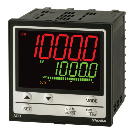
2. Name and Functions ACD-13A ACR-13A (10) (10) (11) (14) (14) (11) (12) (12) (15) (15) (13) (13) (16) (16) (17) (17) (Fig. 2-1) - 9 -... - Page 10 Displays, Indicators (1) PV indicator Lights when PV is indicated in PV/SV Display Mode. (2) PV Display Indicates the PV or setting characters in setting mode. (3) SV/MV/TIME indicator Lights when SV is indicated in PV/SV Display Mode. Lights when MV is indicated in PV/SV Display Mode. TIME: Lights when remaining step time (program control) is indicated in PV/SV Display Mode.
- Page 11 Keys (11) UP key: Increases the numeric value. If this key is pressed for 1 second during program operation (RUN), the unit proceeds to the next step. (This is the Advance function.) (12) DOWN key: Decreases the numeric value. (13) SET key Switches setting groups.
-
Page 12: Mounting To The Control Panel
3. Mounting to the Control Panel 3.1 External Dimensions (Scale: mm) Terminal cover Screw type ACD-13A (Sold separately) Gasket mounting bracket 11.5 98.5 104.5 (When terminal cover is used) (Fig. 3.1-1) ACR-13A Terminal cover Screw type Gasket mounting bracket (Sold separately) 11.5... -
Page 13: Panel Cutout (Scale: Mm)
3.2 Panel Cutout (Scale: mm) Caution If horizontal close mounting is used for the controller, IP66 specification (Drip-proof/ Dust-proof) may be compromised, and all warranties will be invalidated. ACD-13A n×96-3 +0.5 Horizontal close mounting n: Number of mounted units +0.8 □92... -
Page 14: Ct (Current Transformer) External Dimensions (Scale: Mm)
CTL-6-S-H (for 20 A) CTL-12-S36-10L1U (for 100 A) (Fig. 3.3-1) 3.4 Mounting to and Removal from the Control Panel (Common to ACD-13A, ACR-13A) Caution As the case is made of resin, do not use excessive force while screwing in the mounting bracket, or the case or mounting brackets could be damaged. -
Page 15: Wiring
(Fig.3.4-1) 4. Wiring Warning Turn the power supply to the instrument OFF before wiring or checking. Working on or touching the terminal with the power switched ON may result in severe injury or death due to electrical shock. 4.1 Lead Wire Solderless Terminal Use a solderless terminal with an insulation sleeve in which an M3 screw fits as shown below. -
Page 16: Terminal Arrangement
4.2 Terminal Arrangement ACD-13A Power Supply Option C (Serial communi- C5 (Serial communi- EI (Event input) cation cation RS-485) RS-232C) 24 V AC/DC 100 to 240 V AC DI3 (*) YA(-) DI4 (*) YB(+) OUT1 (Relay contact) (Non-contact voltage) (Direct current) (*) If C, C5 (Serial communication) and EI (Event input) are applied together, Event input DI3, DI4 cannot be used. - Page 17 ACR-13A Power Supply Option C5 (Serial communi- C (Serial communi- EI (Event input) cation cation RS-485) RS-232C) 24 V AC/DC 100 to 240 V AC DI3 (*) YA(-) DI4 (*) YB(+) OUT1 (Relay contact) (Non-contact voltage) (Direct current) (*) If C, C5 (Serial communication) and EI (Event input) are applied together, Event input DI3, DI4 cannot be used.
-
Page 18: Wiring Example
Alarm unit Thermocouple Heater • Number of Shinko SSR units when connected in parallel: SA-400 series: 5 units, SA-500 series: 2 units • For a 24 V AC/DC of power source, do not confuse polarity when using a direct current (DC). - Page 19 Current transformer (CT1, CT2) input (W, W3 option) (1) This alarm is not usable for detecting current under phase control. (2) Use the current transformer (CT) provided, and pass one lead wire of heater circuit into the hole of the CT. (3) When wiring, keep CT wire away from AC sources and load wires to avoid the external interference.
-
Page 20: Outline Of Key Operation And Setting Groups
5. Outline of Key Operation and Setting Groups There are 2 setting methods for this controller; Simplified setting (traditional setting method), Group selection. For each setting method, refer to page 21 and subsequent pages. POWER ON (*1) (*1) Standby mode (*2) PV/SV Display Mode Manual control (*3) -
Page 21: Setup
6. Setup Factory default of this controller: Input type: K, -200 to 1370 Control action: PID control (with AT), Reverse action (Heating action) Event output (EVT1, EVT2): No event Setup (setting the Input type, control action, Event output type, etc.) should be done before using this controller, according to the user’s conditions. - Page 22 Power restore action Stops after power is restored. Program start temperature • Communication group (C or C5 option) (pp. 43-44) Setting Item Factory Default Communication protocol Shinko protocol Instrument number Communication speed 9600 bps Data bit/Parity 7 bits/Even Stop bit SVTC bias •...
- Page 23 • Transmission output group (TA1 or TV1 option) (p. 46) Setting Item Factory Default Transmission output type PV transmission Transmission output high limit 1370 Transmission output low limit -200 • Other function group (pages 47-51) Setting Item Factory Default Set value lock Unlock PID zone function Not used...
-
Page 24: Turn The Power Supply To The Unit On
6.1 Turn the Power Supply to the Unit ON. After the power is turned on, the PV Display indicates the input type, and the SV/MV/TIME Display indicates the input range high limit value (thermocouple, RTD inputs) or scaling high limit value (DC voltage, current inputs) for approximately 3 seconds. -
Page 25: Basic Operation Of Settings
6.2 Basic Operation of Settings To proceed to each setting mode, refer to each setting mode. • To set each setting item, use the key. • If the key is pressed, the set value is registered, and the unit proceeds to the next setting item. -
Page 26: Engineering Group
6.3 Engineering Group 6.3.1 Input Group To enter the Input group, follow the procedure below. Press the key 4 times in PV/SV Display Mode. The unit enters the Engineering group. Press the key. The unit proceeds to the Input group. Press the key. - Page 27 Character Setting Item, Function, Setting Range Factory Default -328 to 1832 32 to 3200 32 to 3200 32 to 3308 -328 to 1472 -328.0 to 752.0 -328 to 2372 32 to 2534 C(W/Re5-26) 32 to 4199 Pt100 -328.0 to 1562.0 JPt100 -328.0 to 932.0...
- Page 28 Character Setting Item, Function, Setting Range Factory Default Decimal point place No decimal point • Selects decimal point place. Available only for DC voltage and current inputs. • : No decimal point : 1 digit after decimal point : 2 digits after decimal point : 3 digits after decimal point : 4 digits after decimal point PV filter time constant...
-
Page 29: Output Group
6.3.2 Output Group To enter the Output group, follow the procedure below. Press the key 4 times in PV/SV Display Mode. The unit enters the Engineering group. Press the key. The unit proceeds to the Input group. Press the key. The unit proceeds to the Output group. Press the key. - Page 30 Character Setting Item, Function, Setting Range Factory Default OUT2 cooling method Air cooling • Selects OUT2 cooling method from air, oil or water cooling. Available when the D option is ordered. Not available if OUT2 is in ON/OFF control. OUT2 proportional band •...
- Page 31 Character Setting Item, Function, Setting Range Factory Default OUT1 MV preset output 0.0% • If Preset output 1 or 2 is selected in [Event input allocation], OUT1 MV can be set. Preset output 1: Control is performed with the preset output MV if sensor is burnt out during Event Input ON.
-
Page 32: Event Input Group
6.3.3 Event Input Group This group is available only when the EI option is ordered. To enter the Event input group, follow the procedure below. Press the key 4 times in PV/SV Display Mode. The unit enters the Engineering group. Press the key. - Page 33 Input ON Input OFF Selected Event input function Remarks (Closed) (Open) value Preset output 1 Preset output Standard If sensor is burnt (*2) control out, the unit maintains control with the preset output MV. Auto/Manual control Manual Automatic control control Remote/Local Remote Local...
-
Page 34: Event Output Group
(*1) The value that 1 (one) is added to 2 , is indicated on the MEMO/STEP Display. (e.g.) If EVI1(2 )=OFF, EVI2(2 )=ON, then 3 (2 +1) is indicated. and 2 will be allocated to Event input EVI1 to EVI4 respectively, and the Set value memory number will be determined by each value of EVI1 to EVI4. - Page 35 Event Output Allocation Table Event output Proceeding to the lower Selected Remarks function level with the value No event Alarm output; Alarm hysteresis High limit alarm Alarm delay time Alarm Energized/De-energized Alarm output; Same as the High limit alarm Low limit alarm Alarm output;...
- Page 36 Event output Proceeding to the lower Selected Remarks function level with the value Heater rated current Select the rated Heater burnout alarm current 20 A or output Heater burnout alarm 1 value 100 A. (Can be set within the Heater burnout alarm 2 value selected rated current.) (*)
- Page 37 • Alarm output setting items [When Alarm output (001 to 012) is selected] Character Setting Item, Function, Setting Range Factory Default Alarm hysteresis • Sets Alarm hysteresis. • Setting range: 0.1 to 1000.0 DC voltage, current inputs: 1 to 10000 (The placement of the decimal point follows the selection.) Alarm delay time 0 seconds...
- Page 38 • Timer output setting items [When Timer output (013, 014) is selected] Available only when the EI option is ordered. Character Setting Item, Function, Setting Range Factory Default Timer output delay action ON delay time • Selects a Timer output action. •...
- Page 39 • Heater burnout alarm output setting items [When Heater burnout alarm output (015) is selected] Available only when W, W3 option is ordered. Character Setting Item, Function, Setting Range Factory Default Heater rated current 20.0 A • Selects heater rated current. •...
- Page 40 • Loop break alarm output setting items [When Loop break alarm output (016) is selected] Character Setting Item, Function, Setting Range Factory Default Loop break alarm time 0 minutes • Sets the time to assess the Loop break alarm. • Setting to 0 (zero) disables the alarm. •...
- Page 41 • Time signal output setting items [When Time signal output (017) is selected] Character Setting Item, Function, Setting Range Factory Default Time signal output step • Sets step number for time signal output performance. • Setting range: 1 to 15 Time signal output OFF time 00:00 •...
-
Page 42: Program Group
6.3.5 Program Group To enter the Program group, follow the procedure below. Set the key 4 times in PV/SV Display Mode. The unit enters the Engineering group. Press the key. The unit proceeds to the Input group. Press the key multiple times until characters of the Program group appear. -
Page 43: Communication Group
Factory Default Communication protocol Shinko protocol • Selects communication protocol. • : Shinko protocol : MODBUS ASCII mode : MODBUS RTU mode Instrument number • Sets the instrument number. The instrument numbers should be set one by one when multiple instruments are connected in Serial communication, otherwise communication is impossible. - Page 44 Factory Default SVTC bias • SV adds SVTC bias value to the value received via SV digital transmission (SVTC command). Available only when Shinko protocol is selected in [Communication protocol]. • Setting range: Converted value of 20% of input span...
-
Page 45: External Setting Group
6.3.7 External Setting Group Available only when the EA or EV option is ordered. To enter the External setting group, follow the procedure below. Set the key 4 times in PV/SV Display Mode. The unit enters the Engineering group. Press the key. -
Page 46: Transmission Output Group
6.3.8 Transmission Output Group Available only when TA1 or TV1 option is ordered. To enter the Transmission output group, follow the procedure below. Set the key 4 times in PV/SV Display Mode. The unit enters the Engineering group. Press the key. -
Page 47: Other Function Group
6.3.9 Other Function Group To enter Other function group, follow the procedure below. Set the key 4 times in PV/SV Display Mode. The unit enters the Engineering group. Press the key. The unit proceeds to the Input group. Press the key multiple times until characters of Other function group appear, or press the key. - Page 48 Character Setting Item, Function, Setting Range Factory Default SV fall rate /minute • Sets SV fall rate (falling value for 1 minute). When the SV is adjusted, it approaches the new SV by the preset rate-of-change ( /min, /min). When the power is turned on, the control starts from the PV, and approaches the SV by the rate-of-change.
- Page 49 Character Setting Item, Function, Setting Range Factory Default Backlight time 0 minutes • Sets time to backlight from no operation status until backlight is switched off. When set to 0, the backlight remains ON. Backlight relights by pressing any key while backlight is OFF. •...
- Page 50 [PV Display color selection] (Table 6.3.9-1) PV Color Selection PV Color Constantly green : Green Constantly red : Red Constantly orange : Orange : When any alarm output When alarm output OFF: Green from EVT1 to EVT5 is ON: When any alarm output from EVT1 to EVT5 Green Red (*) is ON, the PV color turns from green to red.
- Page 51 [Bar Graph Indication] MV or DV are indicated on the bar graph. With MV indication, if Heating/Cooling control output is ordered, bar graph indication for OUT1 MV and OUT2 MV differs as shown below. Function Contents Indication Scale is -5 to 105%, (e.g.) OUT1 MV 50% indication and segments light...
-
Page 52: Settings
There are 2 setting methods for this controller: Simplified setting, Group selection. 7.1 Simplified Setting Method Simplified setting method, which is effective for the Fixed value control, is the same method as when setting standard Shinko controllers. 7.1.1 SV Setting Mode To enter the SV setting mode, press the key in PV/SV Display Mode. - Page 53 Character Setting Item, Function, Setting Range Factory Default EVT2 alarm value • Sets EVT2 alarm value. If the independent alarm (High/Low limits independent, High/Low limit range independent, or High/Low limits with standby independent) is selected in [Event output EVT2 allocation], the EVT2 alarm value matches the EVT2 low limit alarm value.
- Page 54 Character Setting Item, Function, Setting Range Factory Default EVT4 alarm value • Sets EVT4 alarm value. If the independent alarm (High/Low limits independent, High/Low limit range independent, or High/Low limits with standby independent) is selected in [Event output EVT4 allocation], the EVT4 alarm value matches the EVT4 low limit alarm value.
- Page 55 (Table 7.1.2-1) Alarm Type Setting Range High limit alarm (deviation setting) -(Input span) to input span ( ) *1 Low limit alarm (deviation setting) -(Input span) to input span ( ) *1 High/Low limits alarm (deviation setting) 0 to input span ( ) *1 High/Low limits independent alarm 0 to input span...
-
Page 56: Pid Setting Mode
7.1.3 PID Setting Mode To enter PID setting mode, press and hold the keys (in that order) together for 3 seconds in PV/SV Display Mode. If PID zone function “Used” is selected, settable PID zone parameters depends on the SV. PID zone numbers are indicated on the MEMO/STEP Display. - Page 57 Setting Item, Function, Setting Range Factory Default Character OUT1 rate-of-change 0 %/second • Sets changing value of OUT1 MV for 1 second. Setting the value to 0 disables this function. Not available if OUT1 is in ON/OFF control. See “OUT1 rate-of-change” below. •...
-
Page 58: Group Selection
7.2 Group Selection There are 4 groups to be set for the controller; ‘SV, Event group’, PID group, AT group and Engineering group. Select a group with the key, and set each item in the group with the key. PV Display Group Setting Items •... - Page 59 Setting Item, Function, Setting Range Factory Default Character EVT1 high limit alarm value • Sets EVT1 high limit alarm value. Setting the value to 0 or 0.0 disables this alarm (except Process high and Process low alarm). Available when the independent alarm (High/Low limits independent, High/Low limit range independent, or High/Low limits with standby independent) is selected in [Event output EVT1 allocation].
- Page 60 Setting Item, Function, Setting Range Factory Default Character EVT4 alarm value • Sets EVT4 alarm value. If the independent alarm (High/Low limits independent, High/Low limit range independent, or High/Low limits with standby independent) is selected in [Event output EVT4 allocation], the EVT4 alarm value matches the EVT4 low limit alarm value.
- Page 61 EVT5 high limit alarm value • Sets EVT5 high limit alarm value. Setting the value to 0 or 0.0 disables this alarm (except Process high and Process low alarm). Available when the independent alarm (High/Low limits independent, High/Low limit range independent, or High/Low limits with standby independent) is selected in [Event output EVT5 allocation].
-
Page 62: Program Pattern Group (For Program Control)
7.2.2 Program Pattern Group (for Program Control) Sets Step SV, Step time, Wait value and Event (EVT1 to EVT5) in this group. A maximum of 15 steps of program pattern can be created. This program pattern shows that the Step temperature rises to 200 for 1 hour, and stays at 200... - Page 63 To enter the Program pattern group, follow the procedure below. Press the key in PV/SV Display Mode. The unit proceeds to the Program pattern group. Press the key. The unit proceeds to ‘Step 1 SV’. Setting Item, Function, Setting Range Factory Default Character Step 1 SV...
- Page 64 Setting Item, Function, Setting Range Factory Default Character Step 1 EVT2 alarm value • Sets Step 1 EVT2 alarm value. If the independent alarm (High/Low limits independent, High/Low limit range independent, or High/Low limits with standby independent) is selected in [Event output EVT2 allocation], the EVT2 alarm value matches the EVT2 low limit alarm value.
- Page 65 Setting Item, Function, Setting Range Factory Default Character Step 1 EVT4 high limit alarm value • Sets Step 1 EVT4 high limit alarm value. Setting the value to 0 or 0.0 disables this alarm (except Process high and Process low alarm). Available when the independent alarm (High/Low limits independent, High/Low limit range independent, or High/Low limits with standby independent) is selected in [Event output EVT4 allocation].
-
Page 66: Pid Group
7.2.3 PID Group PID parameters can be set in this group. PID group is common to Fixed value control and program control. To enter the PID group, follow the procedure below. Press the key twice in PV/SV Display Mode. The unit proceeds to the PID group. Press the key. - Page 67 Setting Item, Function, Setting Range Factory Default Character Derivative time 1 50 seconds • Sets derivative time 1 for OUT1. Setting the value to 0 disables this function. • Setting range: 0 to 1800 seconds ARW 1 • Sets ARW 1 (anti-reset windup 1) for OUT1. •...
-
Page 68: At Group
7.2.4 AT Group AT/Auto-reset Perform/Cancel, AT bias can be set in this group. AT group is common to Fixed value control and program control. During ON/OFF control or PI control, the unit cannot proceed to any setting items in this group. If PID zone function “Used”... -
Page 69: Operation
8. Operation 8.1 Starting Operation After the unit is mounted to the control panel and wiring is completed, operate the unit following the procedure below. (1) Turn the power supply to the unit ON. After the power is turned on, the PV Display indicates the input type, and the SV/MV/TIME Display indicates the input range high limit value (for thermocouple, RTD inputs) or scaling high limit value (for DC voltage, current inputs) for approximately 3 seconds. - Page 70 • When Control output OFF function is working The PV Display indicates [ ]. (Indication depends on the selection in [Indication when output OFF].) • Program control standby status The PV Display indicates the PV, and the SV/MV/TIME Display and MEMO/STEP Display are turned off.
-
Page 71: Control Output Off Function
(e.g.) When setting the SV to 100 in the Fixed value control. Proceed to SV setting mode. Press the key in PV/SV Display Mode. The unit proceeds to the SV setting mode. Set SV. Set SV with the key. Register the SV. Press the key to register the SV. -
Page 72: Switching Auto/Manual Control
8.3 Switching Auto/Manual Control By pressing the key in PV/SV Display Mode, Auto/Manual control can be switched. If control action is switched from automatic to manual and vice versa, balanceless- bumpless function works to prevent a sudden change of MV. When automatic control is switched to manual control, the MEMO/STEP Display indicates [ ]. - Page 73 How to perform AT/Auto-reset (1) Press the key 3 times in PV/SV Display Mode. The unit proceeds to the AT group. (2) Press the key. The unit proceeds to [AT/Auto-reset]. (3) Select AT/Auto-reset “Perform [ ]” with the key, and press the key.
-
Page 74: Using Event Output As A High/Low Limits Independent Alarm
8.6 Using Event Output as a High/Low Limits Independent Alarm To use the Event output as a High/Low limits independent alarm, set as follows. (e.g.) SV: 100 EVT1 (low limit) alarm value: 10 EVT1 high limit alarm value: 20 (Fig. 8.6-1) (1) Select [Engineering group] –... - Page 75 Set Event output EVT1 alarm delay time. Use the for settings, and press the key. The unit proceeds to Event output EVT1 alarm Energized/ De-energized. Select Event output EVT1 alarm Energized/De-energized. Use the for selection, and press the for 3 seconds. (3 sec) The unit reverts to PV/SV Display Mode.
-
Page 76: Set Value Memory Function
8.7 Set Value Memory Function If ‘Set value memory’ is selected in [Event input EVI1 to EVI4 allocation], memory file numbers can be selected by external operation. Up to 15 files with 13 pieces of data can be memorized. Control can be performed by selecting the desired file number. In one file, 13 pieces of data are included: SV, Step time, Wait value, EVT1 alarm value, EVT1 high limit alarm value, EVT2 alarm value, EVT2 high limit alarm value, EVT3 alarm value, EVT3 high limit alarm value, EVT4 alarm value, EVT4 high limit alarm value,... - Page 77 Group selection (Fixed value control) (1) Proceed to the setting item of the desired Set value memory number in the ‘SV, Event group’. (2) Set the following values: SV, EVT1 alarm value, EVT1 high limit alarm value, EVT2 alarm value, EVT2 high limit alarm value, EVT3 alarm value, EVT3 high limit alarm value, EVT4 alarm value, EVT4 high limit alarm value, EVT5 alarm value, EVT5 high limit alarm value [Registration complete]...
-
Page 78: Auto-Reset
9. Auto-reset Auto-reset is performed to correct the offset at the point at which PV indication is stabilized within the proportional band during the PD control. Since the corrected value is internally memorized, it is not necessary to perform the auto-reset again as long as the process is the same. - Page 79 10. AT In order to set each value of P, I, D and ARW automatically, the AT process should be made to fluctuate to obtain an optimal value. One of 3 types of fluctuation below is automatically selected. For DC voltage, current inputs, the AT process will fluctuate around the SV for conditions of [1], [2] and [3].
- Page 80 [1] If there is a large difference between the SV and PV as the temperature is rising When AT bias is set to 20 , the AT process will fluctuate at the temperature 20 lower than the SV. Temperature 20 lower than the SV (1) Calculates PID constants.
-
Page 81: Action Explanation
11. Action Explanation 11.1 OUT1 Action Heating ( reverse) action Cooling (direct ) action Proportional band Proportional band Control action Cycle action is performed Cycle action is performed according to deviation according to deviation 12 V DC 12/0 V DC 0 V DC 0/12 V DC 12 V DC... -
Page 82: Out1 On/Off Control Action
11.2 OUT1 ON/OFF Control Action Heating (reverse) action Cooling (direct) action Hysteresis Hysteresis Control action 12V DC 0 V DC 0 V DC 12 V DC 20 mA DC 4 mA DC 4 mA DC 20 mA DC Indicator (OUT1 ) Unlit Unlit : ON (lit) or OFF (unlit) -
Page 83: Alarm Action
11.3 Alarm Action Low limit alarm High limit alarm EVT1 hysteresis EVT1 hysteresis Alarm action - EVT1 value - EVT1 value +EVT1 value +EVT1 value + side + side Alarm output - side - side High/ Low limits alarm High/ Low limits independent alarm EVT1 hysteresis EVT1 hysteresis Alarm... - Page 84 Low limit alarm with standby High limit alarm with standby EVT1 hysteresis EVT1 hysteresis Alarm action - EVT1 value - EVT1 value +EVT1 value +EVT1 value + side + side Alarm output - side - side High/Low limits with standby High/Low limits with standby independent EVT1 hysteresis EVT1 hysteresis...
-
Page 85: Heater Burnout Alarm Action
11.4 Heater Burnout Alarm Action • EVT1 indicator lights when their output terminals 9 and 10 are closed (ON), and turns off when their output terminals 9 and 10 are opened (OFF). The following shows EVT2 to EVT5 terminals. EVT2 output (terminals 7 and 8) (For A3 option, use terminals 8 and 10.) EVT3 output (terminals 7 and 10) EVT4 output (terminals 29 and 30) EVT5 output (terminals 28 and 30) -
Page 86: Out2 (Heating/Cooling Control) Action
11.5 OUT2 (Heating/Cooling control) Action Heating P-band Cooling P-band Control Heating Cooling action action action Cycle action is performed according to deviation. Cycle action is performed according to deviation. 12 V DC 12/0 V DC 0 V DC Cycle action is performed according to deviation. -
Page 87: Out2 (Heating/Cooling Control) Action (When Setting Dead Band)
11.6 OUT2 (Heating/Cooling Control) Action (When Setting Dead Band) Heating P-band Dead band Cooling P-band Heating Control (Cooling action action action) Cycle action is performed according to deviation. Cycle action is performed according to deviation. 12 V DC 12/0 V DC 0 V DC Cycle action is performed according to deviation. -
Page 88: Out2 (Heating/Cooling Control) Action (When Setting Overlap Band)
11.7 OUT2 (Heating/Cooling Control) Action (When Setting Overlap Band) Heating P-band Cooling P-band Heating action Overlap band Control Heating (Cooling action action action) Cycle action is performed according to deviation. Cycle action is performed according to deviation. 12 V DC 12/0 V DC 0 V DC Cycle action is performed... -
Page 89: Specifications
Allowable voltage fluctuation: 100 to 240 V AC: 85 to 264 V AC voltage 24 V AC/DC: 20 to 28 V AC/DC General structure External ACD-13A: 96 x 96 x 100 mm (W x H x D) dimensions ACR-13A: 48 x 96 x 100 mm (W x H x D) Mounting Flush... - Page 90 SV/MV/TIME 11-segment LCD 5-digit, Backlight Green Display Character size: ACD-13A: 14.0 x 7.0 mm (H x W) ACR-13A: 10.0 x 4.6 mm (H x W) MV/DV 22-segment LCD bar graph, Backlight Green bar graph MEMO/STEP 11-segment LCD 2-digit, Backlight Orange...
- Page 91 Control action OUT1 0 to Input span proportional DC voltage, current inputs: 0.0 to 1000.0% band (ON/OFF control when set to 0 or 0.0) (Factory default: 10 ) Integral time 0 to 3600 seconds (OFF when set to 0) (Factory default: 200 seconds) Derivative 0 to 1800 seconds (OFF when set to 0) time...
- Page 92 When Alarm action (Energized) is selected in [Event output Alarm action allocation], the alarm action point is set by the deviation from the SV (except Process alarm). When the input goes outside the range, the output turns ON or OFF (in the case of High/Low limit range alarm).
- Page 93 When the SV is adjusted, it approaches the new SV by the preset SV ramp rate-of-change ( /minute, /minute). function When the power is turned on, the control starts from the PV and approaches the SV by the rate-of-change. Power failure The setting data is backed up in the non-volatile IC memory.
- Page 94 Console By connecting the USB communication cable (CMB-001) to the communication Console connector of the instrument, the following operations can be conducted from an external computer using the Console software SWS-AC001M. Console communication and Serial communication (C, C5 option) cannot be used together. (1) Reading and setting of SV, PID and various set values (2) Reading of PV and action status (3) Function change...
-
Page 95: Optional Specifications
ACD-13A: Approx. 460 g Weight ACR-13A: Approx. 330 g Accessories For the ACD-13A and ACR-13A: included Mounting brackets: 1 set, Instruction manual: 1 copy Gasket (Front mounted to the unit): 1 piece For the ACR-13A only: Harness EVT5:1 piece [When Event output (A5 option) is ordered]... - Page 96 Event output (Option code: A5) EVT4 and EVT5 are available. The output will be turned ON or OFF depending on the conditions selected in [Event output allocation]. Output Relay contact, 1a Control capacity: 3 A 250 V AC (Resistive load) 1 A 250 V AC (Inductive load, cos =0.4) Electric life: 100,000 cycles Heater burnout alarm (including sensor burnout alarm) [Option code: W, W3]...
- Page 97 7 bits, 8bits / Even, Odd and No parity (Selectable by keypad) (Factory default: 7 bits/Even) Stop bit 1, 2 (Selectable by keypad) (Factory default: 1) Communication Shinko protocol / MODBUS ASCII / MODBUS RTU (Selectable by protocol keypad) (Factory default: Shinko protocol) Communication Shinko...
- Page 98 Parity, checksum (Shinko protocol), LRC (MODBUS ASCII), error detection CRC-16 (MODBUS RTU) Digital external Receives step SV from the connected Shinko programmable setting controllers PCA1 or PCB1 (Select ‘SV digital transmission’ in [Communication protocol]). SV adds SVTC bias value to the step SV received via SV digital transmission (SVTC command).
-
Page 99: Troubleshooting
13. Troubleshooting If any malfunctions occur, refer to the following items after checking that power is being supplied to the controller. 13.1 Indication Problem Possible Cause and Solution • Control output OFF function is working. ], nothing or PV Press the key for approx. -
Page 100: Key Operation
• AC leaks into the sensor circuit. Use an ungrounded type sensor. • There may be equipment that interferes with or makes noise near the controller. Keep ACD-13A or ACR-13A clear of any potentially disruptive equipment. • Internal memory is defective. ] is indicated on Contact our agency or us. -
Page 101: Control
13.3 Control Possible Cause and Solution Problem Temperature does not • Sensor is out of order. Replace the sensor. rise. • Check whether the Sensor or control output terminals are securely mounted to the instrument input terminals. Ensure that the sensor or control output terminals are mounted to the instrument input terminals securely. -
Page 102: Character Tables
14. Character Tables The PV Display indicates setting characters, and the SV/MV/TIME Display indicates factory default. [Simplified Setting] SV setting mode Character Setting Item, Setting Range Data Setting range: Scaling low limit to Scaling high limit Event setting mode Character Setting Item, Setting Range Data EVT1 alarm value... - Page 103 (Table 14-1) Alarm Type Setting Range High limit alarm (Deviation setting) -(Input span) to Input span ( ) *1 Low limit alarm (Deviation setting) -(Input span) to Input span ( ) *1 High/Low limits alarm 0 to Input span ( ) *1 (Deviation setting) High/Low limits independent 0 to Input span...
- Page 104 [Group Selection] SV, Event group (for Fixed value control) Character Setting Item, Setting Range Data SV, Event group Setting range: Scaling low limit to Scaling high limit EVT1 alarm value Setting range: Refer to (Table 14-1) on p.103. EVT1 high limit alarm value Setting range: Refer to (Table 14-1) on p.103.
- Page 105 Program pattern group (for Program control) Character Setting Item, Setting Range Data Program pattern group Step 1 SV Setting range: Scaling low limit to Scaling high limit Step 1 time Setting range: 00:00 to 99:59 Step 1 Wait value Setting range: 0 to Converted value of 20% of input span Step 1 EVT1 alarm value Setting range: Refer to (Table 14-1) on p.103.
- Page 106 Character Setting Item, Setting Range Data Step 1 EVT5 high limit alarm value Setting range: Refer to (Table 14-1) on p.103. Step 2 SV Step 2 time Step 2 Wait value Step 2 EVT1 alarm value Step 2 EVT1 high limit alarm value Step 2 EVT2 alarm value Step 2 EVT2 high limit alarm value Step 2 EVT3 alarm value...
- Page 107 Character Setting Item, Setting Range Data Step 4 EVT5 high limit alarm value Step 5 SV Step 5 time Step 5 Wait value Step 5 EVT1 alarm value Step 5 EVT1 high limit alarm value Step 5 EVT2 alarm value Step 5 EVT2 high limit alarm value Step 5 EVT3 alarm value Step 5 EVT3 high limit alarm value...
- Page 108 Character Setting Item, Setting Range Data Step 8 time Step 8 Wait value Step 8 EVT1 alarm value Step 8 EVT1 high limit alarm value Step 8 EVT2 alarm value Step 8 EVT2 high limit alarm value Step 8 EVT3 alarm value Step 8 EVT3 high limit alarm value Step 8 EVT4 alarm value Step 8 EVT4 high limit alarm value...
- Page 109 Character Setting Item, Setting Range Data Step 11 EVT1 alarm value Step 11 EVT1 high limit alarm value Step 11 EVT2 alarm value Step 11 EVT2 high limit alarm value Step 11 EVT3 alarm value Step 11 EVT3 high limit alarm value Step 11 EVT4 alarm value Step 11 EVT4 high limit alarm value Step 11 EVT5 alarm value...
- Page 110 Character Setting Item, Setting Range Data Step 14 EVT2 alarm value Step 14 EVT2 high limit alarm value Step 14 EVT3 alarm value Step 14 EVT3 high limit alarm value Step 14 EVT4 alarm value Step 14 EVT4 high limit alarm value Step 14 EVT5 alarm value Step 14 EVT5 high limit alarm value Step 15 SV...
- Page 111 PID group Character Setting Item, Setting Range Data PID group PID zone value 1 Setting range: Scaling low limit to Scaling high limit OUT1 proportional band 1 Setting range: 0 to Input span DC voltage, current inputs: 0.0 to 1000.0% OUT2 proportional band 1 Setting range: 0.0 to 10.0 times (Multiplied value of OUT1 proportional band)
- Page 112 Integral time 3 Derivative time 3 ARW 3 Manual reset 3 OUT1 rate-of-change 3 PID zone value 4 OUT1 proportional band 4 OUT2 proportional band 4 Integral time 4 Derivative time 4 ARW 4 Manual reset 4 OUT1 rate-of-change 4 PID zone value 5 OUT1 proportional band 5 OUT2 proportional band 5...
- Page 113 Engineering group Character Setting Item, Setting Range Data Engineering group Input group Character Setting Item, Setting Range Data Input group Input type -200 1370 -200.0 400.0 -200 1000 1760 1760 1820 -200 -200.0 400.0 -200 1300 1390 C(W/Re5-26) 2315 Pt100 -200.0 850.0 JPt100...
- Page 114 C(W/Re5-26) 4199 Pt100 -328.0 1562.0 JPt100 -328.0 932.0 Pt100 -328 1562 JPt100 -328 Pt100 -148.0 212.0 Pt100 -148.0 932.0 0 to 20 mA DC -2000 10000 0 to 10 mV DC -2000 10000 -10 to 10 mV DC -2000 10000 0 to 50 mV DC -2000 10000...
- Page 115 Output group Character Setting Item, Setting Range Data Output group OUT1 proportional cycle Setting range: 1 to 120 seconds OUT2 proportional cycle Setting range: 1 to 120 seconds OUT1 high limit Setting range: OUT1 low limit to 100% (Direct current output: OUT1 low limit to 105%) OUT1 low limit Setting range: 0% to OUT1 high limit (Direct current output: -5% to OUT1 high limit)
- Page 116 OUT1 MV preset output Setting range: 0.0 to 100.0% (Direct current output: -5.0 to 105.0%) OUT2 MV preset output Setting range: 0.0 to 100.0% (Direct current output: -5.0 to 105.0%) Event input group Character Setting Item, Setting Range Data Event input group Event input EVI1 allocation Refer to Event Input Allocation Table.
- Page 117 Selected Input ON Input OFF Event input function Remarks value (Closed) (Open) Auto/Manual control Manual Automatic control control Remote/Local Remote Local Effective only when or EV option is ordered Program mode; STOP Level action when RUN/STOP power is turned on Program mode;...
- Page 118 Event Output Allocation Table Event output Proceeding to the lower level Selected Remarks function with the value No event Alarm output; Alarm hysteresis High limit alarm Alarm delay time Alarm Energized/De-energized Alarm output; Same as the High limit alarm Low limit alarm Alarm output;...
- Page 119 Selected Event output Proceeding to the lower level Remarks value function with the Heater rated current Select the rated Heater burnout alarm current 20 A or output Heater burnout alarm 1 value 100 A. (Can be set within the selected Heater burnout alarm 2 value rated current.) Loop break alarm time...
- Page 120 Heater burnout alarm output setting items: When ‘Heater burnout alarm output’ is selected in [Event output allocation]. Character Setting Item, Setting Range Data Heater rated current : 20.0 A : 100.0 A Heater burnout alarm 1 value Rated current 20.0 A: 0.0 to 20.0 A, 100.0 A: 0.0 to 100.0 A Heater burnout alarm 2 value Rated current 20.0 A: 0.0 to 20.0 A,...
- Page 121 Setting range: Scaling low limit to Scaling high limit value Communication group Character Setting Item, Setting Range Data Communication group Communication protocol : Shinko protocol : MODBUS ASCII mode : MODBUS RTU mode Instrument number Setting range: 0 to 95 Communication speed : 9600 bps : 19200 bps...
- Page 122 Character Setting Item, Setting Range Data Stop bit SVTC bias Setting range: Converted value of 20% of input span DC voltage, current inputs: 20% of scaling span (The placement of the decimal point follows the selection.) External setting group Character Setting Item, Setting Range Data External setting group...
- Page 123 Character Setting Item, Setting Range Data Transmission output high limit PV, SV transmission: Transmission output low limit to Input range high limit value MV transmission: Transmission output low limit to 105.0% DV transmission: Transmission output low limit to Scaling span Transmission output low limit PV, SV transmission: Input range low limit to Transmission output high limit value...
- Page 124 Character Setting Item, Setting Range Data Indication when output OFF : OFF indication : No indication : PV indication : PV indication+ Any event output from EVT1 to EVT5 Backlight selection : All (Displays and indicators) are backlit. : PV Display is backlit. : SV/MV/TIME+MV/DV Bar Graph Displays are backlit.
- Page 125 Program Pattern Table Step number Step SV Step time ( : ) Wait value EVT1 alarm value EVT1 high limit alarm value EVT2 alarm value EVT2 high limit alarm value EVT3 alarm value EVT3 high limit alarm value EVT4 alarm value EVT4 high limit alarm value EVT5 alarm value EVT5 high limit alarm value...
-
Page 127: Operation Flowchart
15. Operation Flowchart Simplified setting and group selection are explained separately. All setting items are used for the purpose of explanation, however some items will not be displayed depending on the specification. 15.1 Simplified Setting (SV, Event, PID Setting Modes: For Fixed Value Control Only) POWER ON (*1) (*1) -
Page 128: Group Selection (For Fixed Value Control)
15.2 Group Selection (for Fixed Value Control) POWER ON (*1) The unit starts from the power-off status. (*1) (*2) For Fixed value control, if this key is pressed for 1 second, (*1) PV/SV Display Mode and standby mode can be switched. PV/SV Display Mode Standby mode (*3) If power is turned off during manual control, the unit starts... - Page 129 [Key operation] • This means that if the key is pressed, the unit proceeds to the next setting MODE MODE mode, illustrated by an arrow. • Pressing the key for 1 second reverts to the previous setting level. • If the key is pressed for 3 seconds at any group or setting item, the unit reverts to MODE PV/SV Display Mode.
-
Page 130: Group Selection (For Program Control)
15.3 Group Selection (for Program Control) POWER ON (*1) The unit starts from the power-off status. (*1) (*2) For program control, control runs or stops. (*1) (*3) If power is turned off during manual control, the unit starts PV/SV Display Mode Standby mode from the PV/SV Display Mode. - Page 131 [Key operation] • This means that if the key is pressed, the unit proceeds to the next setting MODE: MODE mode, illustrated by an arrow. • Pressing the key for 1 second reverts to the previous setting level. • If the key is pressed for 3 seconds at any group or setting item, the unit reverts to MODE PV/SV Display Mode.
- Page 132 • Serial number ------------------ No. 123456789 In addition to the above, please let us know the details of the malfunction, or discrepancy, and the operating conditions. SHINKO TECHNOS CO., LTD. OVERSEAS DIVISION Head Office 2-5-1, Senbahigashi, Minoo, Osaka, Japan http://www.shinko-technos.co.jp/e/...
Need help?
Do you have a question about the ACD-13A and is the answer not in the manual?
Questions and answers