Table of Contents
Advertisement
Quick Links
Advertisement
Table of Contents

Related Manuals for Shinko ACD-15A-R/M


Summary of Contents for Shinko ACD-15A-R/M
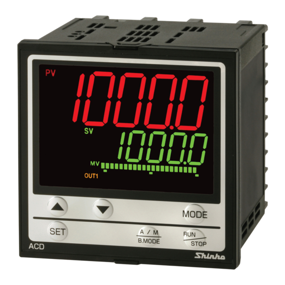
- Page 1 ON/OFF SERVO DIGITAL INDICATING CONTROLLERS ACD-15A, ACR-15A INSTRUCTION MANUAL...
- Page 2 • Any unauthorized transfer or copying of this document, in part or in whole, is prohibited. • Shinko Technos Co., Ltd. is not liable for any damage or secondary damage(s) incurred as a result of using this product, including any indirect damage.
- Page 3 Caution This instrument is intended to be used under the following environmental conditions (IEC61010-1): Overvoltage category , Pollution degree 2 Ensure the mounting location corresponds to the following conditions: • A minimum of dust, and an absence of corrosive gases •...
- Page 4 Caution • It is recommended that auto-tuning (AT) be performed during the trial run. • Do not touch live terminals. This may cause electrical shock or problems in operation. • Turn the power supply to the instrument OFF when retightening the terminal and cleaning.
-
Page 5: Table Of Contents
CONTENTS 1. Model ............................ 7 1.1 Model ..........................7 1.2 How to Read the Model Label ..................7 2. Names and Functions ......................8 3. Mounting to the Control Panel ....................11 3.1 External Dimensions (Scale: mm) ................... 11 3.2 Panel Cutout (Scale: mm) ....................12 3.3 Mounting to, and Removal from, the Control Panel (Common to ACD-15A, ACR-15A) .. - Page 6 9.5 AT/Auto-reset Perform, AT Cancel ................. 68 9.6 Using Event Output as a High/Low Limits Independent Alarm ........70 9.7 Set Value Memory Function ................... 72 10. Auto-reset .......................... 73 11. AT (Auto-tuning) ......................... 73 12. Action Explanation ......................75 12.1 Control Output Action ....................
-
Page 7: Model
1. Model 1.1 Model ACD-1 5 A - R / M ACD-15A (W96 x H96 x D100 mm) ACR-1 5 A - R / M ACR-15A (W48 x H96 x D100 mm) Control ON/OFF SERVO PID action Event output Selectable by front keypad (*1) EVT1 Control output Relay contact: 1a x 2 (Open/Closed) -
Page 8: Names And Functions
2. Names and Functions ACD-15A ACR-15A (10) (10) (11) (14) (14) (11) (12) (12) (15) (15) (13) (13) (16) (16) (17) (17) (Fig. 2-1) Displays (1) PV indicator Lights when PV is indicated in PV/SV Display Mode. (2) PV Display Indicates the PV or setting characters in the setting mode. - Page 9 (5) MV/DV indicator MV: Lights when MV or degree of valve opening is indicated on the bar graph. DV: Lights when DV is indicated on the bar graph. (6) MV/DV/Valve Bar Graph Display MV, DV or degree of valve opening is indicated on the bar graph. (7) MEMO/STEP indicator MEMO : Lights when a Set value memory number is indicated.
- Page 10 (15) RUN/STOP key For Fixed value control, PV/SV Display Mode or standby mode can be switched by pressing this key for 1 second. In the standby mode, pressing this key turns all outputs OFF as when the power supply is turned off. In the program mode, control RUNS/STOPS.
-
Page 11: Mounting To The Control Panel
3. Mounting to the Control Panel 3.1 External Dimensions (Scale: mm) ACD-15A Screw type Terminal cover mounting bracket Gasket A (Sold separately) 11.5 98.5 104.5 (When terminal cover is used) (Fig. 3.1-1) Terminal cover ACR-15A Screw type (Sold separately) mounting bracket Gasket A 11.5 98.5... -
Page 12: Panel Cutout (Scale: Mm)
3.2 Panel Cutout (Scale: mm) Caution If horizontal close mounting is used for the controller, IP66 specification (Drip-proof/ Dust-proof) may be compromised, and all warranties will be invalidated. ACD-15A n×96-3 +0.5 Horizontal close mounting n: Number of mounted units +0.8 □92 (Fig. -
Page 13: Mounting To, And Removal From, The Control Panel (Common To Acd-15A, Acr-15A)
3.3 Mounting to, and Removal from, the Control Panel (Common to ACD-15A, ACR-15A) Caution As the case is made of resin, do not use excessive force while screwing in the mounting bracket, or the case or mounting brackets could be damaged. The torque should be 0.12 N•m. -
Page 14: Wiring
4. Wiring Warning Turn the power supply to the instrument OFF before wiring or checking. Working on or touching the terminal with the power switched ON may result in severe injury or death due to electrical shock. 4.1 Terminal Arrangement ACD-15A EVENT INPUT TRANSMIT OUTPUT... -
Page 15: Lead Wire Solderless Terminal
Ground POWER SUPPLY Power supply voltage 100-240 V AC or 24 V AC/DC For a 24 V AC/DC power source, do not confuse polarity when using direct current (DC). OPEN Open output CLOSED Closed output EVT1 EVT1 output EVENT INPUT Event input (EI option) RS-485/RS-232C Serial communication RS-485(C5 option) or RS-232C(C option) -
Page 16: Wiring Example
4.3 Wiring Example ACD-15A-R/M Single phase 200 V Open output Closed output Feedback potentiometer O W C OPEN Furnace CLOSED Thermocouple Control motor Motor valve To prevent the unit from harmful effects of unexpected high level noise, it is recommended that a surge absorber be installed between the electromagnetic switch coils. -
Page 17: Outline Of Key Operation And Setting Groups
5. Outline of Key Operation and Setting Groups There are 2 setting methods for this controller; Simplified setting (traditional setting method), Group selection. For each setting method, refer to page 18 and those which follow it. Power ON (*1) (*1) Standby mode (*2) PV/SV Display Mode... -
Page 18: Operation Flowchart
6. Operation Flowchart Simplified setting and group selection are explained separately. All setting items are used for the purpose of explanation, however some items will not be indicated depending on the specification. 6.1 Simplified Setting (SV, Event and PID setting modes: Effective for Fixed value control) Power ON (*1) (*1) -
Page 19: Group Selection (For Fixed Value Control)
6.2 Group Selection (for Fixed Value Control) Power ON (*1) (*1) PV/SV Display Mode Standby mode (*2) Manual control (*3) (1 sec) SV, Event Engineering group group group group (1 sec) (1 sec) (1 sec) Input PID zone AT/Auto-reset group value 1 (1sec) Proportional... - Page 20 [Key operation] • : This means that if the key is pressed, the unit proceeds to the next setting mode. • Pressing the key for 1 second reverts to the previous setting level. • If the key is pressed for 3 seconds at any group or setting item, the unit reverts to PV/SV Display Mode.
- Page 21 External Transmission Other Communication setting output function group group group group (1 sec) (1 sec) (1 sec) (1 sec) Communication Remote/Local Transmission Set value protocol output type lock Instrument External setting Transmission PID zone number input high limit output high limit function Communication External setting...
-
Page 22: Group Selection (For Program Control)
6.3 Group Selection (for Program Control) Power ON (*1) (*1) PV/SV Display Mode Standby mode (*2) Manual control (*3) (1 sec) Program PID group AT group Engineering pattern group group ① (1 sec) Step 1 SV Same as ‘6.2 Same as ‘6.2 Same as ‘6.2 Group Selection (for Group Selection (for... -
Page 23: Setup
7. Setup Factory default values of this controller: Input type: K, -200 to 1370 Control action: PID control (with AT), Reverse (Heating) action FBP (Feedback potentiometer) Yes Event output (EVT1): No event Setup should occur before using this controller according to the user’s conditions. Setting the input type, control action, Event output action, etc. - Page 24 • Output group (pages 30 to 31) Setting Item Factory Default MV high limit 100% MV low limit ON/OFF hysteresis Direct/Reverse action Reverse action Preset output 0.0% FBP Yes/No Open/Closed output dead band Open/Closed output hysteresis FBP adjustment Stop Open output time 30.0 seconds Closed output time 30.0 seconds...
- Page 25 • Communication group (C or C5 option) (p. 42) Setting Item Factory Default Communication protocol Shinko protocol Instrument number Communication speed 9600 bps Data bit/Parity 7 bits/Even Stop bit SVTC bias • External setting group (EA or EV option) (p. 43)
-
Page 26: Turn The Power Supply To The Unit On
7.1 Turn the Power Supply to the Unit ON. After the power is turned on, the PV Display indicates the input type, and the SV/MV/TIME display indicates the input range high limit value (thermocouple, RTD inputs) or scaling high limit value (DC voltage, current inputs) for approximately 3 seconds. (Table 7.1-1) During this time, all outputs and the indicators are in OFF status. -
Page 27: Engineering Group
7.3 Engineering Group 7.3.1 Input Group To enter the Input group, follow the procedure below. Press the key 4 times in PV/SV Display Mode. The unit will enter the Engineering group. Press the key. The unit will proceed to the Input group. Press the key. - Page 28 Character Name, Function, Setting Range Factory Default -328 to 2498 -328.0 to 752.0 -328 to 1832 32 to 3200 32 to 3200 32 to 3308 -328 to 1472 -328.0 to 752.0 -328 to 2372 32 to 2534 C(W/Re5-26) 32 to 4199 Pt100 -328.0 to...
- Page 29 Character Name, Function, Setting Range Factory Default Decimal point place No decimal point • Selects decimal point place. Available only for DC voltage and current inputs. • : No decimal point : 1 digit after the decimal point : 2 digits after the decimal point : 3 digits after the decimal point : 4 digits after the decimal point PV filter time constant...
-
Page 30: Output Group
7.3.2 Output Group To enter the Output group, follow the procedure below. Press the key 4 times in PV/SV Display Mode. The unit will enter the Engineering group. Press the key. The unit will proceed to the Input group. Press the key. - Page 31 Character Name, Function, Setting Range Factory Default Open/Closed output hysteresis • Sets Open/Closed output hysteresis. Not available if “FBP No" is selected in [FBP Yes/No]. • Setting range: 0 to 100% FBP adjustment Stop • Adjusts the position of FBP (feedback potentiometer) fully closed and fully open.
- Page 32 Name, Function, Setting Range Factory Default Character Open output time 30.0 seconds • Sets time from the motor valve “fully closed” to ”fully open”. Not available if “FBP Yes” is selected in [FBP Yes/No]. • Setting range: 0.1 to 1000.0 seconds Closed output time 30.0 seconds •...
-
Page 33: Event Input Group
7.3.3 Event Input Group This group is available only when EI option is added. To enter the Event input group, follow the procedure below. Press the key 4 times in PV/SV Display Mode. The unit will enter the Engineering group. Press the key. - Page 34 Input ON Input OFF Selected Event input function Remarks (Closed) (Open) value Auto/Manual control Manual Automatic control control Remote/Local Remote Local Effective only when or EV option is added Program mode; Level action when RUN/STOP STOP power is turned on Program mode;...
-
Page 35: Event Output Group
7.3.4 Event Output Group To enter the Event output group, follow the procedure below. Set the key 4 times in PV/SV Display Mode. The unit will enter the Engineering group. Press the key. The unit will proceed to the Input group. Press the key several times until the Event output group characters appear. - Page 36 Selected Event output Proceeding to the lower level Remarks value function with the Alarm output; Same as the High limit alarm Process high alarm Alarm output; Same as the High limit alarm Process low alarm Alarm output; Same as the High limit alarm High limit with standby Alarm output;...
- Page 37 Pattern end output After the program control is completed, pattern end output is turned ON. The following program pattern shows that the temperature rises to 200 for 1 hour, and stays at 200 for 2 hours after program control starts. Step Step SV Step time (hours)
- Page 38 • Alarm output setting items [When Alarm output (001 to 012) is selected] Character Name, Function, Setting Range Factory Default Alarm hysteresis • Sets Alarm hysteresis. • Setting range: 0.1 to 1000.0 ( ) DC voltage, current inputs: 1 to 10000 (The placement of the decimal point follows the selection.) Alarm delay time 0 seconds...
- Page 39 • Timer output setting items [When Timer output (013, 014) is selected] Available only when the EI option is added. Character Name, Function, Setting Range Factory Default Timer output delay action ON delay time • Selects a Timer output action. •...
- Page 40 • Time signal output setting items [When Time signal output (017) is selected] Character Name, Function, Setting Range Factory Default Time signal output step • Sets the step number for time signal output performance. • Setting range: 1 to 15 Time signal output OFF time 00:00 •...
-
Page 41: Program Group
7.3.5 Program Group To enter the Program group, follow the procedure below. Set the key 4 times in PV/SV Display Mode. The unit will enter the Engineering group. Press the key. The unit will proceed to the Input group. Press the key several times until the Program group characters appear. -
Page 42: Communication Group
SVTC bias • Control desired value (SV) adds SVTC bias value to the value received by the SVTC command. • Available only when Shinko protocol is selected in [Communication protocol]. • Setting range: Converted value of 20% of input span... -
Page 43: External Setting Group
7.3.7 External Setting Group Available only when the EA or EV option is added. To enter the External setting group, follow the procedure below. Set the key 4 times in PV/SV Display Mode. The unit will enter the Engineering group. Press the key. -
Page 44: Transmission Output Group
7.3.8 Transmission Output Group Available only when TA1 or TV1 option is added. To enter the Transmission output group, follow the procedure below. Set the key 4 times in PV/SV Display Mode. The unit will enter the Engineering group. Press the key. -
Page 45: Other Function Group
7.3.9 Other Function Group To enter Other function group, follow the procedure below. Set the key 4 times in PV/SV Display Mode. The unit will enter the Engineering group. Press the key. The unit will proceed to the Input group. Press the key several times until Other function group characters appear, or press the... - Page 46 Character Name, Function, Setting Range Factory Default SV fall rate /minute • Sets SV fall rate (falling value for 1 minute). (Refer to “SV rise rate”.) Setting to 0 or 0.0 disables the function. • Setting range: 0 to10000 /minute ( /minute) Thermocouple, RTD inputs with a decimal point: 0.0 to1000.0 /min( /min) DC voltage, current inputs: 0 to 10000/minute (The placement of the...
- Page 47 Character Name, Function, Setting Range Factory Default Backlight time 0 minutes • Sets time to backlight from no operation status until backlight is switched off. When set to 0, the backlight remains ON. Backlight relights by pressing any key while backlight is OFF. •...
- Page 48 [PID zone function] When PID zone function “Used” is selected, and if SV (or Step SV for the program control) is lower than PID zone value, the control is performed with PID zone parameters of the relevant PID zone value. If the next PID zone value is lower than the current one, the next PID zone parameters will not be effective.
- Page 49 [PV Display color selection] (Table 7.3.9-1) PV Color Selection PV Color Constantly green Green Constantly red Constantly orange Orange When alarm output OFF: Green When any alarm output When any alarm output (EVT1, EVT4, EVT5) is (EVT1, EVT4, EVT5) is ON: Green ON, the PV color turns from green to red.
- Page 50 [Bar Graph Indication] MV, DV or Degree of valve opening is indicated on the bar graph. Function Contents Indication Scale is -5 to 105%. (e.g.) Output MV 50% indication Segments light from left to right in accordance with the output MV. 105% Increases to the right in accordance with the output MV.
-
Page 51: Settings
There are 2 setting methods for this controller: Simplified setting, Group selection. 8.1 Simplified Setting Method Simplified setting method, which is effective for the Fixed value control, is the same method as when setting standard Shinko controllers. 8.1.1 SV Setting Mode To enter SV setting mode, press the key in PV/SV Display Mode. - Page 52 Character Name, Function, Setting Range Factory Default EVT4 alarm value • Sets EVT4 alarm value. Setting the value to 0 or 0.0 disables the function (except Process high and Process low alarm). Not available if No event is selected. Available only when Alarm output is selected in [Event output EVT4 allocation].
- Page 53 (Table 8.1.2-1) Alarm type Setting range High limit alarm (deviation setting) -(Input span) to input span ( ) *1 Low limit alarm (deviation setting) -(Input span) to input span ( ) *1 High/Low limits alarm (deviation setting) 0 to input span ( ) *1 High/Low limits independent alarm 0 to input span ( ) *1 (deviation setting)
-
Page 54: Pid Setting Mode
8.1.3 PID Setting Mode To enter the PID setting mode, press the keys (in that order) together for 3 seconds in PV/SV Display Mode. If PID zone function “Used” is selected, PID zone parameters depends on the SV. PID zone numbers are indicated on the MEMO/STEP Display. Character Name, Function, Setting Range Factory Default... -
Page 55: Group Selection
[MV rate-of-change] For Heating control, if PV is lower than SV, output is generally turned from OFF to ON as shown in (Fig. 8.1.3-1). If MV rate-of-change is set, the output can be changed by the rate-of-change (Fig. 8.1.3-2). This control is suitable for high temperature heaters (which are made from molybdenum, tungsten or platinum, etc., and used at approx. -
Page 56: Event Group (For Fixed Value Control)
8.2.1 SV, Event Group (for Fixed Value Control) Sets SV and Event (EVT1, EVT4, EVT5) in this group. If ‘Set value memory’ is selected in [Event input allocation], the setting items in this group can be set for the selected memory numbers. To enter the ‘SV, Event group’, follow the procedure below. - Page 57 Character Name, Function, Setting Range Factory Default EVT4 high limit alarm value • Sets EVT4 high limit alarm value. Setting the value to 0 or 0.0 disables the function (except Process high and Process low alarm). Not available if No event is selected. Available only when Alarm output is selected in [Event output EVT4 allocation].
-
Page 58: Program Pattern Group (For Program Control)
8.2.2 Program Pattern Group (for Program Control) Sets Step SV, Step time, Wait value and Event (EVT1, EVT4, EVT5) in this group. A maximum of 15 steps of program pattern can be created. This program pattern shows that the Step number temperature rises to 200 for 1 hour, and stays at 200... - Page 59 To enter the Program Pattern group, follow the procedure below. Press the key in PV/SV Display Mode. The unit proceeds to the Program Pattern group. Press the key. The unit proceeds to ‘Step1 SV’. Character Name, Function, Setting Range Factory Default Step 1 SV •...
- Page 60 Character Name, Function, Setting Range Factory Default Step 1 EVT4 high limit alarm value • Sets Step 1 EVT4 high limit alarm value. Setting the value to 0 or 0.0 disables the function (except Process high and Process low alarm). Not available if No event is selected.
-
Page 61: Pid Group
8.2.3 PID Group PID parameters can be set in this group. PID group is common to Fixed value control and program control. To enter the PID group, follow the procedure below. Press the key twice in PV/SV Display Mode. The unit proceeds to the PID group. Press the key. - Page 62 Name, Function, Setting Range Factory Default Character Manual reset 1 • Sets reset value 1 manually. • Setting range: 1000.0 DC voltage, current inputs: The placement of the decimal point follows the selection. MV rate-of-change 1 0 %/second • Sets MV rate-of-change 1 (changing value of MV for 1 second). Setting the value to 0 disables the function.
-
Page 63: At Group
8.2.4 AT Group AT/Auto-reset Perform/Cancel, AT bias can be set in this group. AT group is common to Fixed value control and program control. During ON/OFF control or PI control, the unit cannot proceed to any setting items in this group. -
Page 64: Operation
9. Operation 9.1 Starting Operation After the unit is mounted to the control panel and wiring is completed, operate the unit following the procedure below. (1) Turn the power supply to the unit ON. After the power is turned on, the PV Display indicates the input type, and the SV/MV/ TIME Display indicates the input range high limit value (thermocouple, RTD inputs) or scaling high limit value (DC voltage, current inputs) for approximately 3 seconds. - Page 65 • When Control output OFF function is working The PV Display indicates [ ]. (Indication of the PV Display depends on the selection in [Indication when output OFF].) • Program control standby status The PV Display indicates the PV, and the SV/MV/TIME Display and MEMO/STEP Display turn off.
- Page 66 Advance function (proceeds to the next step during program operation) If the key is pressed for 1 second during program control, it interrupts the performing step, and proceeds to the next step. While the Wait function is working, the Wait function is cancelled, and the unit proceeds to the next step.
-
Page 67: Control Output Off Function
9.2 Control Output OFF Function This is a function to pause the control action or turn the control output of the unused instrument of the plural units OFF even if the power to the instrument is supplied. This function is available for Fixed value control. To turn the control output OFF, press the key for 1 second in PV/SV Display Mode. -
Page 68: Indicating Mv And Remaining Step Time (Program Control)
9.4 Indicating MV and Remaining Step Time (program control) To indicate MV, press the key for approximately 3 seconds in PV/SV Display Mode. The SV/MV/TIME Display indicates output MV and the MEMO/STEP Display indicates [ ]. SV and TIME of the SV/MV/TIME indicator are unlit, and MV of the SV/MV/TIME indicator is lit. If the key is pressed again during Fixed value control, the unit reverts to PV/SV Display Mode. - Page 69 How to cancel AT (1) Press the key 3 times in PV/SV Display Mode. The unit proceeds to the AT group. (2) Press the key. The unit proceeds to ‘AT/Auto-reset’. (3) Select [ ] (AT/Auto-reset Cancel) with the key, and press the for 3 seconds.
-
Page 70: Using Event Output As A High/Low Limits Independent Alarm
9.6 Using Event Output as a High/Low Limits Independent Alarm To use the Event output as a High/Low limits independent alarm, set as follows. (e.g.) SV: 100 EVT1 (low limit) alarm value: 10 EVT1 high limit alarm value: 20 (Fig. 9.6-1) (1) Select [Engineering group] –... - Page 71 Set Event output EVT1 alarm delay time. Use the for settings, and press the key. The unit proceeds to ‘Event output EVT1 alarm Energized/De-energized’. Select Event output EVT1 alarm Energized/De-energized. Use the for settings, and press the for 3 seconds. (3sec) The unit reverts to PV/SV Display Mode.
-
Page 72: Set Value Memory Function
9.7 Set Value Memory Function If ‘Set value memory’ is selected in [Event input EVI1 to EVI4 allocation], memory file number can be selected by external operation. Up to 15 files with 9 pieces of data can be memorized. Control can be performed by selecting the desired file. In one file, 9 pieces of data are included: SV, Step time, Wait value, EVT1 alarm value, EVT1 high limit alarm value, EVT4 alarm value, EVT4 high limit alarm value, EVT5 alarm value, EVT5 high limit alarm value. -
Page 73: Auto-Reset
10. Auto-reset Auto-reset is performed to correct the offset at the point at which PV indication is stabilized within the proportional band during the PD control. Since the corrected value is internally memorized, it is not necessary to perform the auto-reset again as long as the process is the same. - Page 74 [1] If there is a large difference between the SV and PV as the temperature is rising When AT bias is set to 20 , the AT process will fluctuate at the temperature 20 lower than the SV. Temperature 20 lower than the SV (1) Calculates PID constant (2) PID constant calculated...
-
Page 75: Action Explanation
12. Action Explanation 12.1 Control Output Action Heating (reverse) action Cooling (direct) action Proportional band Proportional band Control action Open output terminals Closed output terminals Cycle action is performed Cycle action is performed according to deviation according to deviation Action indicator OPEN Unlit Unlit... -
Page 76: Alarm Action
12.4 Alarm Action Low limit alarm High limit alarm EVT1 hysteresis EVT1 hysteresis Alarm action - EVT1 value - EVT1 value +EVT1 value +EVT1 value + side + side Alarm output - side - side High/ Low limits alarm High/ Low limits independent alarm EVT1 hysteresis EVT1 hysteresis Alarm... - Page 77 Low limit alarm with standby High limit alarm with standby EVT1 hysteresis EVT1 hysteresis Alarm action - EVT1 value - EVT1 value +EVT1 value +EVT1 value + side + side Alarm output - side - side High/Low limits with standby High/ Low limits with standby independent EVT1 hysteresis EVT1 hysteresis...
-
Page 78: Specifications
13. Specifications 13.1 Standard Specifications Rating Input Thermocouple: K, J, R, S, B, E, T, N, PL- , C(W/Re5-26) External resistance, 100 max. (However, B input: External resistance, 40 max.) RTD: Pt100, JPt100, 3-wire type Allowable input lead wire resistance: 10 max. - Page 79 Indication performance Base accuracy: Thermocouple : Within 0.2% of each input span 1 digit, However R, S inputs, 0 to 200 (32 to 392 ): Within (12 ) B input, 0 to 300 (32 to 572 ): Accuracy is not guaranteed. K, J, E, T, N inputs, less than 0 (32 ): Within 0.4% of input span 1 digit...
- Page 80 Standard functions EVT1 output Output is turned ON or OFF depending on the conditions selected in [Event output allocation]. Output: Relay contact 1a Control capacity: 3A 250 V AC (resistive load) 1A 250 V AC (inductive load cos =0.4) Electrical life: 100,000 cycles Alarm action When Alarm action (Energized) is selected in [Event output allocation], the alarm action point is set by the...
- Page 81 Insulation, Dielectric strength Circuit insulation configuration Power supply Open output Event input Serial communication Closed output Transmission output FBP input EVT 1 output External setting EVT 4 output input Input EVT 5 output Insulation resistance: 10 M minimum, at 500 V DC Dielectric strength: Between power terminal and ground (GND): 1.5 kV AC for 1 minute Between input terminal and ground (GND): 1.5 kV AC for 1 minute...
- Page 82 Attached functions: [Sensor correction] Corrects sensor input value. [Set value lock]: Lock 1, Lock 2, Lock 3, Lock 4 [Auto/Manual control switching] Auto/Manual control can be switched using the key in PV/SV Display Mode. [Program control function] Number of steps: 15 Program control starts or stops with the key.
- Page 83 [Input error indication] Output status Contents and Direct (Cooling) Reverse (Heating) Indication action action Overscale Measured value has exceeded OFF or OFF or Indication range MV low limit value MV low limit value high limit value. ] flashes. Underscale Measured value has dropped OFF or OFF or...
-
Page 84: Optional Specifications
[Timer function (linked with the Event input)] If Timer output, which is linked with Event input, is selected in [Event output allocation], and if Timer Start/Stop is selected in [Event input allocation], this function activates. If Event input turns ON, timer counting starts, and Event output turns ON or OFF after delay time has passed. - Page 85 Communication error detection: Parity, checksum (Shinko protocol), LRC (MODBUS ASCII), CRC-16 (MODBUS RTU) Digital external setting: Receives Step SV from Shinko programmable controllers PCA1 or PCB1 (‘SV digital transmission’ should be selected in [Communication protocol]). If data from the PCA1 or PCB1 is higher than the SV high limit or lower than SV low limit value, this instrument ignores the value, and controls at SV high limit or SV low limit value.
- Page 86 External setting input (option code: EA , EV ) SV adds external analog signal to remote bias value. Setting signal: Direct current: 4 to 20 mA DC [Option code: EA1] 0 to 20 mA DC [Option code: EA2] DC voltage: 0 to 1 V DC [Option code: EV1] 1 to 5 V DC [Option code: EV2] Allowable input: EA : 50 mA DC max.
-
Page 87: Troubleshooting
14. Troubleshooting If any malfunctions occur, refer to the following items after checking the power supply to the controller. 14.1 Indication Problem Possible Cause and Solu tion • Control output OFF function is working. ], nothing or PV Press the key for approx. -
Page 88: Key Operation
• Check if polarity of thermocouple or compensating lead wire is correct. • Check whether codes (A, B, B) of RTD match with the instrument terminals. • Check whether the input signal wire for DC voltage (0 to 5 V The PV Display keeps DC, 0 to 10 V DC) and Direct current (0 to 20 mA DC) is indicating the value... -
Page 89: Control
14.3 Control Possible Cause and Solution Problem Temperature does not • Sensor is out of order. Replace the sensor. rise. • Check whether the Sensor or control output terminals are securely mounted to the instrument input terminals. Ensure that the sensor or control output terminals are mounted to the instrument input terminals securely. -
Page 90: Character Tables
15. Character Tables The PV Display indicates setting characters, and the SV/MV/TIME Display indicates factory default value. [Simplified setting] SV setting mode Character Setting Item Data Scaling low limit to Scaling high limit Event setting mode Character Setting Item Data EVT1 alarm value Setting range: Refer to (Table 15-1) on p.91. - Page 91 (Table 15-1) Alarm Type Setting Range High limit alarm (Deviation setting) -(Input span) to Input span ( ) *1 Low limit alarm (Deviation setting) -(Input span) to Input span ( ) *1 High/Low limits alarm (Deviation 0 to Input span ( ) *1 setting) High/Low limits independent alarm 0 to Input span ( ) *1...
- Page 92 [Group selection] SV, Event group (for Fixed value control) Character Setting Item, Setting Range Data SV, Event group Setting range: Scaling low limit to Scaling high limit EVT1 alarm value Setting range: Refer to (Table 15-1) on p. 91. EVT1 high limit alarm value Setting range: Refer to (Table 15-1) on p.
- Page 93 Program Pattern group (for Program control) Character Setting Item, Setting Range Data Program Pattern group Step 1 SV Setting range: Scaling low limit to Scaling high limit Step 1 time Setting range: 00:00 to 99:59 Step 1 Wait value Setting range: 0 to Converted value of 20% of input span Step 1 EVT1 alarm value Setting range: Refer to (Table 15-1) on p.91.
- Page 94 Step 3 EVT1 alarm value Step 3 EVT1 high limit alarm value Step 3 EVT4 alarm value Step 3 EVT4 high limit alarm value Step 3 EVT5 alarm value Step 3 EVT5 high limit alarm value Step 4 SV Step 4 time Step 4 Wait value Step 4 EVT1 alarm value Step 4 EVT1 high limit alarm value...
- Page 95 Step 9 SV Step 9 time Step 9 Wait value Step 9 EVT1 alarm value Step 9 EVT1 high limit alarm value Step 9 EVT4 alarm value Step 9 EVT4 high limit alarm value Step 9 EVT5 alarm value Step 9 EVT5 high limit alarm value Step 10 SV Step 10 time Step 10 Wait value...
- Page 96 Step 14 EVT5 high limit alarm value Step 15 SV Step 15 time Step 15 Wait value Step 15 EVT1 alarm value Step 15 EVT1 high limit alarm value Step 15 EVT4 alarm value Step 15 EVT4 high limit alarm value Step 15 EVT5 alarm value Step 15 EVT5 high limit alarm value PID group...
- Page 97 MV rate-of-change 2 PID zone value 3 Proportional band 3 Integral time 3 Derivative time 3 ARW 3 Manual reset 3 MV rate-of-change 3 PID zone value 4 Proportional band 4 Integral time 4 Derivative time 4 ARW 4 Manual reset 4 MV rate-of-change 4 PID zone value 5 Proportional band 5...
- Page 98 Input group Character Setting Item, Setting Range Data Input group Input type -200 1370 -200.0 400.0 -200 1000 1760 1760 1820 -200 -200.0 400.0 -200 1300 1390 C(W/Re5-26) 2315 Pt100 -200.0 850.0 JPt100 -200.0 500.0 Pt100 -200 JPt100 -200 Pt100 -100.0 100.0 Pt100...
- Page 99 4 to 20 mA DC -2000 10000 0 to 20 mA DC -2000 10000 0 to 10 mV DC -2000 10000 -10 to 10 mV DC -2000 10000 0 to 50 mV DC -2000 10000 0 to 100 mV DC -2000 10000 0 to 1 V DC...
- Page 100 Output group Character Setting Item, Setting Range Data Output group MV high limit Setting range: MV low limit to 100% MV low limit Setting range: 0% to MV high limit value ON/OFF hysteresis Setting range: 0.1 to 1000.0 DC voltage, current inputs: 1 to 10000 (The placement of the decimal point follows the selection.) Direct/Reverse action : Reverse (Heating) action...
- Page 101 Event input group Character Setting Item, Setting Range Data Event input group Event input EVI1 allocation Refer to the Event input allocation table. Event input EVI2 allocation Refer to the Event input allocation table. Event input EVI3 allocation Refer to the Event input allocation table. Event input EVI4 allocation Refer to the Event input allocation table.
- Page 102 Selected Input ON Input OFF Event input function Remarks value (Closed) (Open) Effective only Remote/Local Remote Local when EA option is added Program mode; Level action RUN/STOP STOP when power is turned on Program mode; Level action Holding/Not holding Holding Not holding when power is turned on...
- Page 103 Event output allocation table Event output Proceeding to the lower level Selected Remarks function with the value No event Alarm output; Alarm hysteresis High limit alarm Alarm delay time Alarm Energized/De-energized Alarm output; Same as the High limit alarm Low limit alarm Alarm output;...
- Page 104 Selected Event output Proceeding to the lower level Remarks value function with the No event Loop break alarm time Loop break alarm output Loop break alarm band Time signal output step Time signal Time signal output output is turned Time signal OFF time off when the performing step Time signal ON time...
- Page 105 Loop break alarm setting items (when Loop break alarm is selected in [Event output allocation]) Character Setting Item, Setting Range Data Loop break alarm time Setting range: 0 to 200 minutes Loop break alarm band Setting range: 0 to 150 ( ) or 0.0 to 150.0 DC voltage, current inputs: 0 to 1500 (The placement of the decimal point follows the selection.)
- Page 106 Setting range: Scaling low limit to Scaling high limit Communication group Character Setting Item, Setting Range Data Communication group Communication protocol : Shinko protocol : MODBUS ASCII mode : MODBUS RTU mode Instrument number Setting range: 0 to 95 Communication speed : 9600 bps...
- Page 107 Stop bit SVTC bias Setting range: Converted value of 20% of input span DC voltage, current inputs: 20% of the scaling span (The placement of the decimal point follows the selection.) External setting group Character Setting Item, Setting Range Data External setting group Remote/Local : Local...
- Page 108 Transmission output group Character Setting Item, Setting Range Data Transmission output group Transmission output type : PV transmission : SV transmission : MV transmission : DV transmission Transmission output high limit PV, SV transmission: Transmission output low limit to Input range high limit value MV transmission: Transmission output low limit to 105.0 (%) DV transmission: Transmission output low limit to...
- Page 109 SV fall rate Setting range: 0 to 10000 /minute ( /minute) Thermocouple, RTD input with a decimal point: 0.0 to1000.0 /minute ( /minute) DC voltage, current inputs: 0 to 10000/minute (The placement of the decimal point follows the selection.) Indication when output OFF : OFF indication : No indication : PV indication...
- Page 110 Program pattern table Step number Step SV Step time ( : ) Wait value EVT1 alarm value EVT1 high limit alarm value EVT4 alarm value EVT4 high limit alarm value EVT5 alarm value EVT5 high limit alarm value Time signal output PID zone value Proportional band Integral time...
- Page 112 • Serial number ------------------ No. 198F05000 In addition to the above, please let us know the details of the malfunction, if any, and the operating conditions. SHINKO TECHNOS CO., LTD. OVERSEAS DIVISION Head Office 2-5-1, Senbahigashi, Minoo, Osaka, Japan URL: http://www.shinko-technos.co.jp...
Need help?
Do you have a question about the ACD-15A-R/M and is the answer not in the manual?
Questions and answers