Table of Contents
Advertisement
Advertisement
Table of Contents

Related Manuals for Shinko FCD-13A


Summary of Contents for Shinko FCD-13A
- Page 1 DIGITAL INDICATING CONTROLLER FCD-13A INSTRUCTION MANUAL...
- Page 2 Preface Thank you for purchasing our Digital indicating controller FCD-13A. This manual contains instructions for the mounting, functions, operations and notes when operating the FCD-13A. To prevent accidents arising from the misuse of this controller, please ensure the operator receives this manual .
- Page 3 • Be sure to follow the warnings, cautions and notices. If they are not observed, serious injury or malfunction may occur. • Specifications of the FCD-13A and the contents of this instruction manual are subject to change without notice. • Care has been taken to assure that the contents of this instruction manual are correct, but if there are any doubts, mistakes or questions, please inform our sales department.
- Page 4 • Do not leave wire remnants in the instrument, because they could cause a fire or malfunction. • Use the solderless terminal with an insulation sleeve in which an M3 screw fits when wiring the FCD-13A. • The terminal block of this instrument is designed to be wired from the left side.
-
Page 5: Table Of Contents
--- CONTENTS --- 1. Model 1.1 Model ---------------------------------------------------------------------------------------- 8 1.2 How to read the model label ----------------------------------------------------------- 9 2. Name and functions of sections 2.1 Name of sections ------------------------------------------------------------------------ 10 2.2 Keys ----------------------------------------------------------------------------------------- 11 3. Setup 3.1 Taking the internal assembly out ---------------------------------------------------- 12 3.2 Switch setting (multi-function) -------------------------------------------------------- 12 3.3 Insertion of the internal assembly --------------------------------------------------- 15 4. - Page 6 6.2.3 Auxiliary function setting mode 1 Set value lock --------------------------------------------------------------------------- 28 SV high limit ----------------------------------------------------------------------------- 29 SV low limit ------------------------------------------------------------------------------ 29 Sensor correction ---------------------------------------------------------------------- 29 Overlap/Dead band -------------------------------------------------------------------- 29 Remote/Local setting ------------------------------------------------------------------ 30 Instrument number --------------------------------------------------------------------- 30 Communication speed ---------------------------------------------------------------- 30 Communication protocol ------------------------------------------------------------- 30 6.2.4 Auxiliary function setting mode 2 Scaling high limit ----------------------------------------------------------------------- 31...
- Page 7 (SM option) ---------------------------------------- 39 8. Operation 8.1 When using the FCD-13A as a Temperature controller ------------------------ 40 8.2 When using the FCD-13A as a Simplified programmable controller ------- 41 9. Action explanations 9.1 OUT1 action ----------------------------------------------------------------------------- 42 9.2 Heater burnout alarm action (option) ---------------------------------------------- 42 9.3 ON/OFF control -------------------------------------------------------------------------- 43...
-
Page 8: Model
1 Model 1.1 Model Alphanumeric characters to represent the control output, input or options are entered where underlined. [Example] FCD-13A- R / M, A2 Alarm 2 (A2) output Multi-range input Relay contact output Standard model F C D – 1 3 A –... -
Page 9: How To Read The Model Label
Warning Do not take the inner assembly out nor touch the terminal with the power supply ON. Touching the terminal with the power switched ON may result in severe injury or death due to Electric Shock. 1.2 How to read the model label Model labels are attached to the case and the inner assembly. -
Page 10: Name And Functions Of Sections
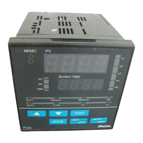
2 Name and functions of sections 2.1 Name of sections (11) (12) (13) (14) (15) (16) (17) (18) (10) (19) (Fig. 2.1-1) (1) PV display (Red) Indicates the PV or setting characters in the setting mode. (2) SV/MV/TIME display (Green) Indicates the SV, MV, Time or each set value in the setting mode. -
Page 11: Keys
(10) TX/RX indicator (Green) (Option) Lights during Serial communication [TX (transmitting) output]. (11) A1 indicator (including Pattern end 1 output) (Red) Lights when the Alarm 1 (A1) output or Pattern end 1 output is on. (12) A2 indicator (including Pattern end 2 output) (Option) (Red) Lights when the Alarm 2 (A2) output or Pattern end 2 output is on. -
Page 12: Setup
3. Setup 3.1 Taking the internal assembly out Before the power supply to this instrument is turned on, take the internal assembly out from the case in the direction indicated by the arrow by pushing the latch (bottom of the instrument) while holding the instrument by the top and bottom. - Page 13 The following items can be selected by the DIP switch (SW304). Default value: All switches OFF (Table 3.2-1) Item SW304 Selection Switch status Fuzzy self-tuning PID control No.1: OFF No.2: OFF PID control No.1: ON No.2: OFF Control action PD control No.1: OFF No.2: ON ON/OFF control...
- Page 14 Select a sensor type using the Rotary switch (SW303) and DIP switch (SW304). Default value: K -200 to 1370 Note: If the input type is changed, Scaling high/low limit, External setting input high/low limit (optional), Transmission output high/low limit (optional) will become the altered input range high/low limit value.
-
Page 15: Insertion Of The Internal Assembly
The alarm type and the pattern end output for program control can be selected by the Rotary switch (SW302) and (SW301). Rotary switch (SW301) will be equipped only when the A2 option is added. Rotary SW302: Alarm 1 (A1) type or Pattern end 1 output Rotary SW301: Alarm 2 (A2) type or Pattern end 2 output Note: If an alarm type is changed, the alarm set value becomes 0 (0.0). -
Page 16: Mounting To The Control Panel
4. Mounting to the control panel 4.1 Site selection This instrument is intended to be used under the following conditions (IEC61010-1): Overvoltage category , Pollution degree 2 Ensure the mounting location corresponds to the following conditions: (1) A minimum of dust, and an absence of corrosive gases (2) No flammable, explosive gases (3) No mechanical vibrations or shocks (4) No exposure to direct sunlight, an ambient temperature of 0 to 50... -
Page 17: Current Transformer (Ct) Dimensions (Scale: Mm)
4.5 Mounting Mountable panel thickness is 1 to 8mm. Insert the FCD-13A from the front of the panel. Attach the mounting brackets to the slots at the top and bottom of the case, and secure the controller in place with the screws provided. -
Page 18: Wiring
5. Wiring Warning Turn the power supply to the instrument off before wiring or checking. Working or touching the terminal with the power switched on may result in severe injury or death due to Electric Shock. Moreover, the instrument must be grounded before the power supply to the instrument is turned on. -
Page 19: Terminal Arrangement
5.1 Terminal arrangement Ground TX[YA(-)] TA or TV RX[YB(+)] 100 to 240V AC RS-232C or 24V AC/DC [RS-485] EA or EV OUT1(R/M) C OUT2(DR)/A2/ P.END2/LA/P24 W or W3 A1/P.END1 OUT1(S/M or A/M) V DC OUT2(DS, DA)/A2/ mA DC P.END2/LA/P24 (Fig. 5.1-1) Dotted lines show options, and no terminal is equipped unless specified. -
Page 20: Wiring Examples
Ground Alarm unit Thermocouple Heater • The connectable SSRs in parallel are 4 units if the Shinko SSRs (SA-300 series) are used. • For a 24V AC/DC power source, do not confuse polarity when using direct current (DC). (Fig. 5.2-2) - Page 21 External operation input [Available only when External setting (EA, EV) option is added] (Fig. 5.2-3) Manual control : Close terminals 26 and 27. Automatic control : Open terminals 26 and 27. Remote setting : Close terminals 25 and 27. Or open terminals 25 and 27, then select “Remote setting” using the keypad.
-
Page 22: Settings
6. Settings Operation flowchart Power ON (*1) (*1) Control output OFF function (Fixed value control) (approx. 1sec) Manual control (Fixed value control) PV/SV display mode (*1) Standby mode (Program control) (approx. 1sec) MV indication Remaining step time indication (*2) (approx. 3sec) (appprox. - Page 23 : Setting items with dotted lines are optional, and they appear only when the options are added. : This means that if the is pressed, the unit proceeds to the next setting item. : Press the key while holding down the key.
-
Page 24: Settings
6.2 Settings The PV display indicates the Sensor type selected during Sensor input selection, and the SV/MV/TIME display indicates input range high limit value or Scaling high limit value for approx. 2 seconds (warm-up status) after power-on. See (Table 6.2-1). During this time, all outputs and LED indicators are in OFF status. -
Page 25: Sub Setting Mode
6.2.2 Sub setting mode In the PV/SV display mode, if the key is pressed while holding down the key, the unit moves to the Sub setting mode. The set value can be increased or decreased using the keys. Pressing the key registers the set value, and proceeds to the next setting item. -
Page 26: Out1 Proportional Cycle
Character Name, Function, Setting range Default value OUT1 proportional cycle R/M: 30 sec • Sets OUT1 proportional cycle. S/M: 3 sec • Not available for DC current output type or if ON/OFF control is selected during Control action selection • For the relay contact output type, if the proportional cycle time is decreased, the frequency of the relay action increases, and the life of the relay contact is shortened. -
Page 27: A3 Value
Character Name, Function, Setting range Default value A3 value • Sets the action point of Alarm 3 (A3) output. • Setting the value to 0 or 0.0 disables the function (except Process high and Process low alarm). • Not available if SA option (A3, A4 output) is not added, or if [ ] is selected during Alarm 3 type selection even if SA option is added. -
Page 28: Auxiliary Function Setting Mode
Since this function has no relation to the memory life, it is well suited when using with Shinko programmable controllers (with SVTC option). -
Page 29: Sv High Limit
Name, Function, Setting range Default value [About Lock 3] When using the FCD-13A as a Fixed value controller The set values of the selected Set value memory number can be changed temporarily. However, if the memory number is changed, the changed values of the previous number are cancelled and returns to the previous values. -
Page 30: Remote/Local Setting
• Available only when the Serial communication (C, C5 option) is added • Selection item: (2400bps) (4800bps) (9600bps) (19200bps) Shinko Communication protocol protocol • Selects the communication protocol of this instrument. • Available only when the Serial communication (C, C5 option) is applied • Selection item: (Shinko protocol) (Modbus ASCII mode) -
Page 31: Auxiliary Function Setting Mode
6.2.4 Auxiliary function setting mode 2 In the PV/SV display mode, if the key is pressed for approx. 3 seconds while holding down the keys, the unit will proceed to Auxiliary function setting mode 2. The set value can be increased or decreased using the keys. -
Page 32: Out1 On/Off Hysteresis
Character Name, Function, Setting range Default value OUT1 ON/OFF hysteresis • Sets ON/OFF hysteresis for OUT1. • Available only when ON/OFF control is selected during Control action selection • Setting range: 0.1 to 100.0 ( ) Air cooling OUT2 action mode •... -
Page 33: A4 Type
Character Name, Function, Setting range Default value A4 type No alarm • Selects an Alarm 4 (A4) type. action Note: If an alarm type is changed, the alarm set value becomes 0 (0.0). • Available only when SA option (A3, A4 output) is added •... -
Page 34: A3 Hysteresis
Character Name, Function, Setting range Default value A3 hysteresis • Sets A3 hysteresis. • Not available if SA option (A3, A4 output) is not added, or if [ ] is selected during Alarm 3 type selection even if SA option is added •... -
Page 35: External Setting Input High Limit
Character Name, Function, Setting range Default value External setting input high limit • Sets External setting input high limit value. For EA option (4 to 20mA), the value corresponds to 20mA input. • Available only when External setting (EA, EV option) is added •... -
Page 36: Sv Fall Rate
Character Name, Function, Setting range Default value SV fall rate 0 /minute • Sets the SV fall rate (Falling value per minute). Setting the value to 0 or 0.0 disables the function. • Setting range: 0 to 9999 /min. With a decimal point: 0.0 to 999.9 /min. DC input: 0 to 9999 (The placement of the decimal point follows the selection.) Output status when input abnormal... -
Page 37: Fixed Value Control/Program Control Switching
• The following shows the program pattern example. Set the step time to 00.00 for any unnecessary steps. [Program example] Step number (Set value memory number) Step SV 1000 1000 OUT1 proportional band Integral time Derivative time OUT1 proportional cycle A1 value A2 value Step time... -
Page 38: Step 6 Time
Character Name, Function, Setting range Default value Step 6 time 00.00 • Sets Step 6 time. (Available only for program control) • Setting range: 00.00 to 99.59 Step 7 time 00.00 • Sets Step 7 time. (Available only for program control) •... -
Page 39: Set Value Memory Function (Sm Option)
To select the set value memory number (file number), connect terminals 13 to 16 as shown below (Table 7-1). Up to 50 units of the FCD-13A can be connected in parallel. Terminal connection for Set value memory number selection (Table 7-1) Set value memory No. -
Page 40: Operation
After the controller is mounted to the control panel and wiring is completed, operate the unit following the procedures below. 8.1 When using the FCD-13A as a Temperature controller (1) Turn the power supply to the FCD-13A ON. For approx. 2sec after power-on, the sensor characters and the temperature unit... -
Page 41: When Using The Fcd-13A As A Simplified Programmable Controller
Instrument status when power is restored When power is restored during program control, the FCD-13A resumes program performance from where it stopped. The PV flashes until the power failure step finishes. -
Page 42: Action Explanations
9 Action explanations 9.1 OUT1 action Heating (reverse) action Cooling (direct) action Proportional band Proportional band Control action Cycle action is performed Cycle action is performed according to deviation. according to deviation. 12V DC 12/0V DC 0V DC 0V DC 0/12V DC 12V DC Cycle action is performed... -
Page 43: On/Off Control
9.3 ON/OFF control Heating (reverse) action Cooling (direct) action Hysteresis Hysteresis Control action 12V DC 0V DC 0V DC 12V DC 20mA DC 20mA DC 4mA DC 4mA DC Indicator (OUT1) Green Unlit Unlit : Acts ON (lit) or OFF (unlit). 9.4 Pattern end action Pattern end Pattern end output is... -
Page 44: Out2 (Heating/Cooling Control) Action (Dr, Ds, Da Option)
9.5 OUT2 (Heating/Cooling control) action (DR, DS, DA option) 9.5.1 OUT2 (Heating/Cooling control) action OUT1 P-band (OUT2 P-band) Heating (Cooling Control action action) action Cycle action is performed according to deviation. Cycle action is performed according to deviation. 12V DC 12/0V DC 0V DC Cycle action is performed... -
Page 45: When Setting Dead Band
9.5.2 When setting Dead band OUT1 P-band Dead band (OUT2 P-band) Control Heating (Cooling action action action) Cycle action is performed according to deviation. Cycle action is performed according to deviation. 12V DC 12/0V DC 0V DC Cycle action is performed according to deviation. -
Page 46: When Setting Overlap Band With Relay Contact Output
9.5.3 When setting Overlap band with Relay contact output. OUT1 P-band OUT2 P-band Overlap band Control Heating (Cooling action action) action Cycle action is performed according to deviation. Cycle action is performed according to deviation. Indicator (OUT1) Green Unlit Indicator (OUT2) Yellow Unlit : Acts ON (lit) or OFF (unlit). -
Page 47: Alarm 1 (A1) To Alarm 4 (A4) Action
9.6 Alarm 1 (A1) to Alarm 4 (A4) action High limit alarm Low limit alarm hysteresis hysteresis Alarm action -A1 value +A1 value -A1 value +A1 value +side +side Alarm output -side -side High/Low limit range alarm High/Low limits alarm hysteresis hysteresis Alarm action... - Page 48 High/Low limits alarm with standby High/Low limit range alarm with standby hysteresis hysteresis Alarm action A1 value A1 value A1 value A1 value Alarm output Process high alarm with standby Process low alarm with standby hysteresis hysteresis Alarm action A1 value A1 value Alarm output : A1 output terminals 9 and 10 are connected.
-
Page 49: Control Actions
10 Control actions 10.1 Fuzzy self-tuning Fuzzy self-tuning is a function to perform a fine adjustment of PID values automatically. Stable control can be carried out even if the conditions of the production process are changed due to various external factors (types and rates of production). (1) When using the controller for the first time, perform the AT (auto-tuning) or set the proper PID values by keypad operation. -
Page 50: At (Auto-Tuning) Of This Controller
10.3 AT (auto-tuning) of this controller In order to set each value of P, I and D automatically, AT process should be made to fluctuate to obtain an optimal value. Sometimes the AT process will not fluctuate if AT is performed at or near room temperature. -
Page 51: Attached Functions
11 Attached functions (1) Burnout When the thermocouple or RTD input is burnt out, OUT1 and OUT2 are turned off (for DC current output type, OUT1, OUT2 low limit value), and the PV display flashes “ ”. For manual control, the preset manipulated variable (MV) is outputted. When DC input is disconnected, PV display flashes “... -
Page 52: Specifications
(3) Self-diagnosis The CPU is monitored by a watchdog timer, and when an abnormal status is found on the CPU, the controller is switched to warm-up status. (4) Automatic cold junction temperature compensation (Thermocouple input type) This detects the temperature at the connecting terminal between the thermocouple and the instrument, and always maintains it at the same status as if the reference junction location temperature was at 0 (32 ). - Page 53 OUT1 (Control output 1) Relay contact : 1a1b Control capacity, 3A 250V AC (resistive load) 1A 250V AC (inductive load cos =0.4) Electrical life: 100,000 cycles Non-contact voltage : For SSR drive V DC maximum 40mA DC (short circuit protected) DC current : 4 to 20mA DC (Isolated type) Load resistance, maximum 550...
- Page 54 PD control Proportional band (P) : 0.1 to 999.9% Derivative time : 0 to 3600sec (off when set to 0) Proportional cycle : 1 to 120sec Reset Proportional band converted value Thermocouple, RTD input: –199.9 to 999.9 DC input: –1999 to 9999 (The placement of the decimal point follows the selection.) Output high/low limit : 0 to 100% (DC current output: –5 to 105%)
- Page 55 Insulation resistance or more, at 500V DC An insulation test must not be carried out between A-B in the case of (*1) above, and between A-F, B-F, A-G, B-G, C-D-E and F-G in the case of (*2) above because they are electrically insulated from each other.
-
Page 56: Optional Specifications
12.2 Optional specifications Alarm 2 (Option code: A2) The alarm action point is set by the deviation from the SV (except Process alarm). [When the alarm action is set as Energized] When the input goes outside the range, the output turns ON or OFF (in the case of High/Low limit range alarm). - Page 57 Data bit : 7 Parity : Even parity Stop bit : 1 Communication protocol : Shinko protocol, Modbus ASCII (Selectable by keypad) (When Modbus protocol is selected, the digital external setting is not usable.) Shinko communication converter IF-400 is available for the Modbus protocol.
- Page 58 Set value memory number external selection (Option code: SM) Selects the set value memory number from 7 files (the undermentioned data as one file) by external terminals: SV, OUT1 proportional band, Integral time, Derivative time, OUT2 proportional band, Alarm values (A1 to A4), Overlap/Dead band, OUT1 high limit value, OUT1 low limit value, OUT2 high limit value, OUT2 low limit value Memory number : 1 to 7 (7 files) Data...
- Page 59 Insulated power output (Option code: P24) Can be used as a small capacity power source for each sensor and converter. If this option is added, Alarm 2 (A2 option), Heating/Cooling control (DR, DS, DA option) or Loop break alarm (LA option) cannot be added. Output voltage : 24 3V DC (when the load current is 30mA.) Ripple voltage...
-
Page 60: Troubleshooting
13 Troubleshooting If any malfunctions occur, refer to the following items after checking the power and the wiring. Warning Turn the power supply to the instrument off before wiring or checking. Working or touching the terminal with the power switched on may result in severe injury or death due to Electric Shock. - Page 61 <Key operation> Problem Presumed cause and solution The setting mode • Manual control is selected. cannot be selected. Change the mode to Automatic control. The mode cannot be • The mode has been set to “Manual control” by External changed from Manual operation.
-
Page 62: Character Table
SV high limit SV low limit Sensor correction Overlap/Dead band Remote/Local setting Local Instrument number Communication speed 9600bps Communication protocol Shinko protocol <Auxiliary function setting mode 2> Character Item Default Data Scaling high limit 1370 Scaling low limit -200 Decimal point place... - Page 63 PV filter time constant 0.0 sec OUT1 high limit 100% OUT1 low limit OUT1 ON/OFF hysteresis OUT2 action mode Air cooling OUT2 high limit 100% OUT2 low limit OUT2 ON/OFF hysteresis Alarm 3 type No alarm action Alarm 4 type No alarm action Alarm 1 action Energized/De-energized Energized Alarm 2 action Energized/De-energized Energized...
- Page 64 For any inquiries about this unit, please contact the vendor where you purchased the unit after checking the following. [Example] • Model --------------------------- FCD-13A-R/M • Input type ---------------------- K • Option --------------------------- A2, TV, C5, W (20A) • Serial number ----------------- No.
Need help?
Do you have a question about the FCD-13A and is the answer not in the manual?
Questions and answers