Shinko ACS-13A Instruction Manual
Digital indicating controller
Hide thumbs
Also See for ACS-13A:
- Communication instruction manual (16 pages) ,
- Instruction manual (9 pages) ,
- Communication instruction manual (16 pages)
Table of Contents
Advertisement
Advertisement
Table of Contents

Related Manuals for Shinko ACS-13A


Summary of Contents for Shinko ACS-13A
- Page 1 DIGITAL INDICATING CONTROLLER ACS-13A INSTRUCTION MANUAL...
-
Page 2: Contents
• Any unauthorized transfer or copying of this document, in part or in whole, is prohibited. • Shinko Technos CO., LTD. is not liable for any damage or secondary damage(s) incurred as a result of using this product, including any indirect damage. -
Page 3: At Auto-Tuning
• Use the solderless terminal with an insulation sleeve in which the M3 screw fits when wiring the ACS-13A. • The terminal block of this instrument is designed to be wired from the left side. The lead wire must be inserted from the left side of the terminal, and fastened with the terminal screw. -
Page 4: Table Of Contents
4.4 Heater Burnout Alarm Output (W, W3 option) Wiring -------------------- 10 5. Operation Flowchart ---------------------------------------------------------------- 11 6. Setup 6.1 Turn the Power Supply to the ACS-13A ON -------------------------------- 12 6.2 Basic Key Operations ------------------------------------------------------------ 12 6.3 Setup Mode ------------------------------------------------------------------------- 13 7. -
Page 5: Model
1. Model 1.1 Model ACS – 1 3 Series name: ACS-13A (W48 x H48 x D62mm) Control action Alarm type can be selected by keypad. *1 Relay contact: 1a Control output OUT1 Non-contact voltage (for SSR drive): 12V DC 15%... -
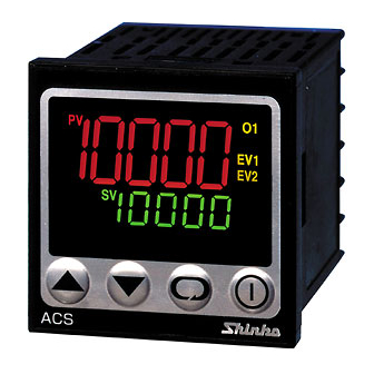
Page 6: Name And Functions Of Controller
2. Name and Functions of Controller (11) (10) (12) (Fig. 2-1) Display (1) PV indicator: Lights when PV is indicated in PV/SV display mode. (2) PV display: Indicates the PV (process variable) or setting characters in each setting mode. (3) SV indicator: Lights when SV is indicated in PV/SV display mode. -
Page 7: Mounting To The Control Panel
3. Mounting to the Control Panel 3.1 External Dimensions (Scale: mm) Mounting frame Terminal cover (sold separately) Gasket A (*) When a terminal cover (sold separately) is used. (Fig. 3.1-1) 3.2 Panel Cutout (scale: mm) Caution If horizontal close mounting is used for the controller, IP66 specification (Drip-proof/Dust-proof) may be compromised, and all warranties will be invalidated. -
Page 8: Mounting To And Removal From The Control Panel
Tighten screws with one rotation upon the screw tips touching the panel. The torque is 0.05 to 0.06N•m. How to mount the ACS-13A Mount the controller vertically to the flat, rigid panel to ensure it adheres to the Drip-proof/Dust-proof specification (IP66). -
Page 9: Wiring
4. Wiring Warning Turn the power supply to the instrument off before wiring or checking. Working on or touching the terminal with the power switched on may result in severe injury or death due to electrical shock. 4.1 Terminal Arrangement POWER SUPPLY 24V AC/DC 100 to 240V AC... -
Page 10: Terminal Cover
4.3 Terminal Cover When using a terminal cover (sold separately), pass terminal wires numbered 7 to 12 into the holes of the terminal cover. Terminal cover (Fig. 4.3-1) 4.4 Heater Burnout Alarm Output (W, W3 Option) Wiring This alarm is not usable for detecting heater current under phase control. Use the CT (current transformer) provided, and pass one lead wire of the heater circuit into the hole of the CT. -
Page 11: Operation Flowchart
5. Operation Flowchart For 3 seconds after the power is turned on, the PV display Power ON indicates the input type, and the SV display indicates input range high limit value (TC, RTD) or scaling high limit value (DC voltage, current). Control output OFF/Manual control PV/SV display mode (Automatic control) Output MV indication... -
Page 12: Setup
Default values: Input (K, -200 to1370 ), Alarm 1 (No alarm action), Reverse (Heating) action If the user’s specification is the same as the default value of the ACS-13A, it is not necessary to set up the controller. Proceed to Section “7. Settings”. -
Page 13: Setup Mode
6.3 Setup Mode To enter Setup mode, press and hold the keys (in that order) together for approx. 3 seconds in PV/SV display mode. Name, Function, Setting range Character Default value Input type K (-200 to 1370 ) • The input type can be selected from thermocouple (10 types), RTD (2 types), DC current (2 types) and DC voltage (4 types), and the unit can be selected as well. - Page 14 Character Name, Function, Setting range Default value PV filter time constant 0.0 seconds • Sets PV filter time constant. If the value is set too high, it affects control results due to the delay of response. • Setting range: 0.0 to 10.0 seconds OUT1 high limit 100% •...
- Page 15 Character Name, Function, Setting range Default value Alarm 1 type No alarm action • Selects an Alarm 1 type. (Refer to ‘11.4 Alarm Action’ on p.29.) • If an alarm type is changed, the alarm value becomes 0 (0.0). : No alarm action : High limit alarm : Low limit alarm : High/Low limits alarm...
- Page 16 Character Name, Function, Setting range Default value SV rise rate 0 /min. • Sets SV rise rate (rising value for 1 minute). Setting to 0 disables the function. • Setting range: 0 to10000 /min. ( /min.) Thermocouple, RTD inputs with a decimal point: 0.0 to1000.0 /min. ( /min.) DC voltage, current inputs: 0 to 10000/min.
- Page 17 Character Name, Function, Setting range Default value Backlight selection All are backlit • Selects the display to backlight. • : All (displays and indicators) are backlit. : Only PV display is backlit. : Only SV display is backlit. : Only Action indicators are backlit. : PV and SV displays are backlit.
- Page 18 [Alarm action Energized/De-energized] When [Alarm Energized ( )] is selected, the alarm output (terminals 3 and 4, or 5 and 6) is conductive (ON) while the alarm output indicator is lit. The alarm output is not conductive (OFF) while the alarm output indicator is not lit. When [Alarm De-energized ( )] is selected, the alarm output (terminals 3 and 4, or 5 and 6) is not conductive (OFF) while the alarm output indicator is lit.
- Page 19 [PV display color selection] (Table 6.3-3) PV color selection PV color Green Constantly green Constantly red Orange Constantly orange When alarm OFF: Green When Alarm 1 or Alarm 2 is ON: When Alarm 1 or Alarm 2 is ON, the PV color turns from Green green to red.
-
Page 20: Settings
7. Settings 7.1 Main Setting Mode To enter Main setting mode, press the key in PV/SV display mode. Character Name, Function, Setting range Default value • Sets SV. • Setting range: Scaling low limit to Scaling high limit • Sets SV2. Not available if the SM option is not ordered, if C5 option is ordered or if ‘OUT/OFF external selection 2’... -
Page 21: Sub Setting Mode
7.2 Sub Setting Mode To enter Sub setting mode, press and hold the keys (in that order) together in PV/SV display mode. Character Name, Function, Setting range Default value AT/Auto-reset • Selects AT (auto-tuning) Perform/Cancel (PID control) or Auto-reset Perform/Cancel (P, PD control). - Page 22 XX.X When OUT1 is ON, the CT1 current value is updated. alternating When OUT1 is OFF, the ACS-13A memorizes the previous value when OUT1 was ON. display Upon returning to set limits, the alarm will stop. Available only when the W or W3 option is ordered.
-
Page 23: Auxiliary Function Setting Mode
Shinko protocol • Selects communication protocol. • Not available if the C5 option is not ordered or if SM option is ordered. • : Shinko protocol : Modbus ASCII mode : Modbus RTU mode Instrument number • Sets the instrument number. -
Page 24: Starting Operation
After the unit is mounted to the control panel and wiring is completed, operate the unit following the procedure below. (1) Turn the power supply to the ACS-13A ON. After the power is turned on, the PV display indicates the input type, and the SV display indicates the input range high limit value (for thermocouple, RTD inputs) or scaling high limit value (for DC voltage, current inputs) for approximately 3 seconds. -
Page 25: Control Output Off Function
8.2 Control Output OFF Function The control action and output of an instrument (or instruments) can be turned OFF without turning OFF their power supplies using this function. To turn the control output OFF, press the key for approximately 1 second. ] is indicated on the PV display while the function is working. -
Page 26: Indicating Output Mv
8.4 Indicating the Output MV To indicate the output MV, press the key for approximately 3 seconds in PV/SV display mode. The MEMO display indicates [ ]. By pressing the key again, the unit reverts to PV/SV display mode. PV/SV display mode (Automatic control) Output MV indication key (approx.3 sec) 8.5 AT/Auto-reset Perform, AT Cancel... -
Page 27: At (Auto-Tuning)
10. AT (Auto-tuning) In order to set each value of P, I, D and ARW automatically, the AT process should be made to fluctuate to obtain an optimal value. One of 3 types of fluctuation below is automatically selected. For DC voltage, current inputs, the AT process will fluctuate around the SV for conditions of [1], [2] and [3] below. Notice •... -
Page 28: Action Explanation
11. Action Explanation 11.1 OUT1 Action Reverse (Heating) action Direct (Cooling) action Proportional band Proportional band Contro action Relay contact output Cycle action is performed Cycle action is performed according to deviation. according to deviation. Non-contact 12V DC 0V DC 0/12V DC 12/0V DC 0V DC... -
Page 29: Heater Burnout Alarm Action
11.3 Heater Burnout Alarm Action Output Alarm action Heater burnout alarm value Small Large Indicator Load current Unlit If Heater burnout alarm and Alarm 2 (A2) option are equipped together, they utilize common output (EV2) terminals. 11.4 Alarm Action “A1” means Alarm 1. For Alarm 2, read “A2” for “A1”. EV1 indicator is for Alarm 1, and EV2 indicator is for Alarm 2. -
Page 30: Out2 (Heating/Cooling Control) Action
11.5 OUT2 (Heating/Cooling Control) Action Heating P-band (Cooling P-band) Heating (Cooling Control action action) action Relay contact output (OUT1) Cycle action is performed according to deviation. Non-contact 12V DC 12/0V DC 0V DC voltage output (OUT1) Cycle action is performed according to deviation. -
Page 31: Out2 (Heating/Cooling Control) Action (When Setting Overlap Band)
11.7 OUT2 (Heating/Cooling Control) Action (When Setting Overlap Band) Heating P-band Cooling P-band Overlap band Control action Heating (Cooling action action) Relay contact output (OUT1) Cycle action is performed according to deviation. Non-contact 12V DC 12/0V DC 0V DC voltage output (OUT1) Cycle action is performed according to deviation. -
Page 32: Specifications
12. Specifications 12.1 Standard Specifications Mounting method: Flush Setting method: Input system using membrane sheet key Display PV display: 11-segment backlight LCD Red/Green/Orange, character size 12.0 x 5.4 mm (H x W) SV display: 11-segment backlight LCD Green, character size 6.0 x 3.5 mm (H x W) MEMO display: 11-segment backlight LCD Green, character size 4.8 x 2.8 mm (H x W) Indicators: Backlight Orange... - Page 33 Control action PID control (with AT function) PI control: When derivative time is set to 0 PD control (with auto-reset function): When integral time is set to 0 P control (with auto-reset function): When derivative and integral time are set to 0. ON/OFF control: When proportional band is set to 0 or 0.0 OUT1 proportional band: 0 to 1000...
- Page 34 PV/SV display mode. Auto/manual control can be switched. [Console communication] By connecting the USB communication cable (Model CMA) to the Console connector of the ACS-13A, the following operations can be conducted from an external computer using the Console software SWS-ACS01M.
-
Page 35: Optional Specifications
Accessories included: Mounting frame 1 piece, Gasket A (Front mounted to the ACS-13A) 1 piece Instruction manual (A3 unfolded, English/Japanese) 1 copy CT (Current transformer): CTL-6-S: 1 piece [W (20A) option] CTL-12-S36-10L1U: 1 piece [W (50A) option] CTL-6-S: 2 pieces [W3 (20A) option]... - Page 36 1 or 2 1 or 2 Number of connectable units: Maximum 31 units to 1 host computer Communication error detection: Parity, checksum (Shinko protocol), LRC (Modbus ASCII), CRC-16 (Modbus RTU) Digital external setting: Receives digital set values from Shinko programmable controllers...
-
Page 37: Troubleshooting
13. Troubleshooting If any malfunctions occur, refer to the following items after checking that power is being supplied to the controller. 13.1 Indication Problem Possible Cause and Solution • Control output OFF function is working. ], nothing or PV is Press the key for approx. -
Page 38: Key Operation
The indication of PV display • Check whether sensor input or temperature unit ( ) is correct. is irregular or unstable. Select the sensor input and temperature unit ( ) properly. • Sensor correcting value is unsuitable. Set it to a suitable value. •... -
Page 39: Character Table
14. Character Table The PV display indicates setting (selection) characters, and the SV display indicates default value. [Main setting mode] Character Setting (Selection) item, Setting range Data Setting range: Scaling low limit to Scaling high limit Setting range: Scaling low limit to Scaling high limit Setting range: Scaling low limit to Scaling high limit Setting range: Scaling low limit to Scaling high limit [Sub setting mode]... - Page 40 SV and Alarm value. Sensor correction Setting range: -100.0 to 100.0 ( ) DC voltage, current inputs: -1000 to 1000 Communication protocol : Shinko protocol : Modbus ASCII mode, : Modbus RTU mode Instrument number Setting range: 0 to 95...
- Page 41 [Setup mode] Character Setting (Selection) item, Setting range Data Input type : K -200 to 1370 : K -320 to 2500 : K -200.0 to 400.0 : K -320.0 to 750.0 : J -200 to 1000 : J -320 to 1800 : R 0 to 1760 : R 0 to 3200 : S 0 to 1760...
- Page 42 Character Setting (Selection) item, Setting range Data OUT2 high limit Setting range: OUT2 low limit to 100% OUT2 low limit Setting range: 0% to OUT2 high limit value Overlap band/Dead band Setting range: -100.0 to 100.0 ( ) DC voltage, current inputs: -1000 to 1000 OUT2 ON/OFF hysteresis Setting range: 0.1 to 100.0 ( ) DC voltage, current inputs: 1 to 1000...
- Page 43 Character Setting (Selection) item, Setting range Data Direct/Reverse control action : Reverse (Heating) control action : Direct (Cooling) control action AT bias Setting range: 0 to 50 (0 to 100 ) Thermocouple, RTD inputs with decimal point: 0.0 to 50.0 (0.0 to 100.0 ) SVTC bias Setting range: Converted value of...
- Page 44 SHINKO TECHNOS CO., LTD. OVERSEAS DIVISION Head Office 2-5-1, Senbahigashi, Minoo, Osaka, Japan http://www.shinko-technos.co.jp/e/ URL: +81-72-727-6100 Tel : E-mail: overseas@shinko-technos.co.jp Fax: +81-72-727-7006 No.ACS12E6 2018.05...
Need help?
Do you have a question about the ACS-13A and is the answer not in the manual?
Questions and answers