Table of Contents
Advertisement
Quick Links
Advertisement
Table of Contents

Related Manuals for Shinko WCL-13A


Summary of Contents for Shinko WCL-13A
- Page 1 PLUG-IN 2ch DIGITAL INDICATING CONTROLLER WCL-13A INSTRUCTION MANUAL...
- Page 2 • Any unauthorized transfer or copying of this document, in part or in whole, is prohibited. • Shinko Technos CO., LTD. is not liable for any damage or secondary damage(s) incurred as a result of using this product, including any indirect damage.
- Page 3 Warning • To prevent an electric shock or fire, only Shinko or other qualified service personnel may handle the inner assembly. • To prevent an electric shock, fire or damage to the instrument, parts replacement may only be undertaken by Shinko or other qualified service personnel.
- Page 4 • If the WCL-13A is installed within a control panel, the ambient temperature of the unit - not the ambient temperature of the control panel - must be kept to under 50 . Otherwise the life of electronic parts (especially electrolytic capacitors) of the unit will be shortened.
-
Page 5: Table Of Contents
6.3 Basic Operation Procedures --------------------------------------------------- 21 7. Key Operation Flowchart --------------------------------------------------------- 22 8. Setup 8.1 Turn the Power Supply to the WCL-13A ON ------------------------------- 24 8.2 CH1 Function Group ------------------------------------------------------------- 25 8.3 CH2 Function Group ------------------------------------------------------------- 30 8.4 Special Function Group --------------------------------------------------------- 34 9. -
Page 6: Model
1. Model 1.1 Model W C L - 1 Series name: WCL-13A Control action 3 Alarm action Alarm type can be selected by keypad. (*1) Relay contact: 1a CH1 control output Non-contact voltage (for SSR drive): 12 V DC 15 %... -
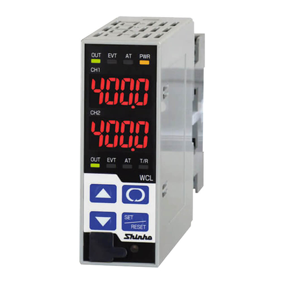
Page 7: Name And Functions Of Sections
2. Name and Functions of Sections CH1 OUT indicator Power indicator CH1 EVT indicator CH1 AT indicator CH1 PV/SV display CH2 PV/SV display CH2 OUT indicator T/R indicator CH2 EVT indicator CH2 AT indicator Increase Key Mode Key Decrease Key SET/RESET Key Console communication Light sensor... -
Page 8: Mounting To The Control Panel
(32 to 122 ) (No icing), Humidity: 35 to 85%RH (Non-condensing) If the WCL-13A is installed within a control panel, the ambient temperature of the unit - not the ambient temperature of the control panel - must be kept to under 50 . -
Page 9: Mounting To A Din Rail
Hook the upper part of the socket on the DIN rail. (Fig. 3.4-1) Caution Before inserting the WCL-13A into the socket, wire the unit while referring to Section “5. Wiring”. (2) Check that the Lock Release has been lowered. Lock Release (Fig. 3.4-2) - Page 10 When inserting, be careful about the position of pins and slots. (Fig. 3.4-3) (4) Fix the WCL-13A and the socket by pushing the Lock Release up. Check that the WCL-13A and the socket are locked by pushing the Lock Release up.
-
Page 11: Removal From A Din Rail
4. Removal from a DIN Rail (1) Turn the power supply to the unit OFF. (2) Pull the Lock Release down, and release the WCL-13A from the socket. Check that the WCL-13A and the socket are unlocked by pulling the Lock Release down. -
Page 12: Wiring
(4) Remove the socket from the DIN rail by pulling the Socket Lock Release (at the bottom of the socket) down. (Fig. 4-3) 5. Wiring Warning Turn the power supply to the instrument off before wiring or checking. Working on or touching the terminal with the power switched on may result in severe injury or death due to electric shock. -
Page 13: 2Ch Controller Spec
5.2 2ch Controller Spec. (*3) CT input CH1 input CH1 output 0 to 1V 0 to 5V 1 to 5V 0 to 10V RS-485 CH2 output [Serial communication (C5 option)] Modular jack pin arrangement: CH2 input 0 to 1V (*1) 0 to 5V 1 to 5V 0 to 10V... -
Page 14: Potentiometer Input Spec
5.4 Potentiometer Input Spec. CT input CH1 input CH1 output 0 to 1V 0 to 5V 1 to 5V 0 to 10V (*2) CH1 output RS-485 [Serial communication (C5 option)] Modular jack pin arrangement: RS-485 Supply voltage (The above diagram shows controller side arrangement.) (*1) For DC current input, connect a 50 shunt resistor (sold separately) between input terminals. -
Page 15: Wiring Example
5.5 Wiring Example • WCL-13A-RR/MM (2ch controller spec: Relay contact output and Multi-range input for both CH1 and CH2) 3-phase To prevent the unit being damaged by the harmful effects of unexpected high level noise, it is recommended that a surge absorber be installed between the electromagnetic switch coils. -
Page 16: Wiring Example Of Heater Burnout Alarm (W, W3 Option)
(1) Pass the Heater wire into the CT hole, and solder the wires of the wire harness provided. (2) CH1: Insert the wire harness into the CT1 input connector. CH2: Insert the wire harness into the CT3 input connector. WCL-13A top view Solder the wires of the wire harness. (There is no polarity.) -
Page 17: Wiring Example Of Alarm Output (Ao Option)
CH2 Alarm 1 output CH2 Alarm 2 output Output specifications are shown below. Open collector: Control capacity, 0.1 A 24 V DC Wiring Example of Alarm Output WCL-13A top view CH2 input WCL-13A interior Alarm unit Wire harness DC power supply... -
Page 18: Wiring Example Of Heater Burnout Alarm (Single-Phase) + Alarm Output (Aw Option)
(2) CH1: Insert the wire harness into the CH1 CT input connector. CH2: Insert the wire harness into the CH2 CT input connector. Wiring Example of Heater Burnout Alarm (CT) input and Alarm Output WCL-13A top view WCL-13A interior Alarm unit... -
Page 19: Wiring Example Of Serial Communication (C5 Option)
The terminator is mounted at the end of the wire when connecting a personal computer with multiple peripheral devices. The terminator prevents signal reflection and disturbance. Do not connect the terminator with the communication line because the WCL-13A has built-in pull-up and pull-down resistors instead of a terminator. -
Page 20: Outline Of Key Operation And Setting Groups
6. Outline of Key Operation and Setting Groups 6.1 Outline of Key Operation Setting items are divided into groups, and group selection has to be made with keypads. Press the key in the PV/SV display mode. The unit enters the Group selection mode. Select a group with the , and press the . -
Page 21: Basic Operation Procedures
6.3 Basic Operation Procedures Basic operation procedures are shown below. Setting Example CH2 function : Used as a CH2 controller (2ch controller spec). Input : Pt100: -199.9 to 850.0 (for CH1, CH2) Control action : PID control (P, I, D and ARW values are automatically set by performing AT) (for CH1, CH2) Alarm 1 type : High limit alarm (for CH1, CH2) Alarm 1 value : 10.0... -
Page 22: Key Operation Flowchart
7. Key operation flowchart Power ON (*9) PV/SV display mode PV/SV Switching Mode PV(SV) switches while is pressed. In the PV/SV display mode, the Indications differ depending on the selection in the CH1, CH2 parameter group. SV can be indicated when PV is PV/SV display mode Indicates the item selected during Display selection in indicated, and vice versa. - Page 23 [About Setting Items] CH1 SV • Upper left (CH1 PV/SV display): Indicates setting item characters. Lower left (CH2 PV/SV display): Indicates default value. Right side: Indicates the Setting item. • Setting items with dotted lines are optional, and they appear only when the options are added. •...
-
Page 24: Setup
Setup can be conducted in the CH1, CH2 function groups and Special function group. If the users’ specification is the same as the default value of the WCL-13A, it is not necessary to set up the controller. Proceed to Chapter “9. Settings”. -
Page 25: Ch1 Function Group
8.2 CH1 Function Group To enter the CH1 function group, follow the procedures below. Press the key in the PV/SV display mode until the left characters appear. Press the key. The CH1 input type will appear. Name, Function, Setting Range Default Value Character Input type... - Page 26 Character Name, Function, Setting Range Default Value Emissivity 0.900 times • Sets infrared emissivity. Setting characters and PV are alternately indicated on the CH1 PV/SV display. Available only for Infrared thermocouple input. • Setting range: 0.100 to 1.000 times Output high limit 100 % •...
- Page 27 Character Name, Function, Setting Range Default Value Overlap band/Dead band • Sets the overlap band or dead band for OUT1 and OUT2. + Set value: Dead band, –Set value: Overlap band • Available when Heating/Cooling control output is selected from the Block function (Console software).
- Page 28 Character Name, Function, Setting Range Default Value Alarm 4 type No Alarm action • Selects an Alarm 4 type. (Refer to Alarm 1 type.) • Available only when the AO option is added. Alarm 1 hysteresis • Sets Alarm 1 hysteresis. •...
- Page 29 Character Name, Function, Setting Range Default Value SV rise rate /min. • Sets SV rise rate (rising value for 1 minute). Setting to 0 or 0.0 disables the function. • Setting range: 0 to 9999 /min. ( /min.) Thermocouple, RTD input with a decimal point: 0.0 to 999.9 /min.
-
Page 30: Ch2 Function Group
8.3 CH2 Function Group Not available for Timer spec or Potentiometer input spec. Not available if Heating/Cooling control output is selected from the Block function (Console software). To enter the CH2 function group, follow the procedures below. Press the key in the PV/SV display mode until the left characters appear. Press the key. - Page 31 Character Name, Function, Setting Range Default Value Emissivity 0.900 times • Sets infrared emissivity. Setting characters and PV are alternately indicated on the CH1 PV/SV display. Available only for Infrared thermocouple input • Setting range: 0.100 to 1.000 times Output high limit 100 % •...
- Page 32 Character Name, Function, Setting Range Default Value Alarm 2 type No Alarm action • Selects an Alarm 2 type. (Refer to Alarm 1 type.) • Available only when the AO or AW option is added. Alarm 3 type No Alarm action •...
- Page 33 Character Name, Function, Setting Range Default Value SV rise rate /min. • Sets SV rise rate (rising value for 1 minute). Setting to 0 or 0.0 disables the function. • Setting range: 0 to 9999 /min. ( /min.) Thermocouple, RTD input with a decimal point: 0.0 to 999.9 /min.
-
Page 34: Special Function Group
Shinko protocol • Selects communication protocol. • Available when the Serial communication (C5) option is added. • : Shinko protocol : Modbus ASCII mode : Modbus RTU mode Instrument number • Sets the instrument number individually to each instrument when communicating by connecting plural instruments in Serial communication. - Page 35 Name, Function, Setting Range Default Value Character Remote/Local Local • SV can be set with either the Remote or Local method. • Available when the External setting input is selected from the Block function (Console software). • : Local (The SV can be set by the front keypad as usual.) : Remote (The SV can be set in analog by external remote operation.) External setting scaling high limit 1370...
- Page 36 Name, Function, Setting Range Default Value Character Timer action Control timer • Selects the timer action. (Refer to the Control timer and Delay timer function on p.38) Available for Timer spec. • : Control timer : Delay timer 1 : Delay timer 2 Timer action time unit Minute •...
- Page 37 Name, Function, Setting Range Default Value Character Display selection CH1 PV / CH2 PV • Selects items to be indicated on the PV/SV display. PV (SV) switches while is pressed in the PV/SV display mode. However, if CH1 or CH2 difference or addition inclusive item is selected, PV (SV) does not switch. •...
- Page 38 Control Timer Function Control timer starts if CH1 input exceeds Control timer start temperature, and after Control timer set time has passed, the control (Output low limit value for DC current output) and Alarm action stop. However, for the Direct control action, Control timer starts when CH1 input drops below the CH1 timer start temperature.
-
Page 39: Settings
9. Settings 9.1 SV Group Not available for Potentiometer input spec. To proceed to the SV group, follow the procedures below. To enter the SV group, press the Key once in the PV/SV display mode. Press the Key. CH1 SV setting item will appear. Name, Function, Setting Range Default Value Character... -
Page 40: Ch1 Parameter Group
9.2 CH1 Parameter Group To proceed to CH1 parameter group, follow the procedures below. Press the key twice in the PV/SV display mode. The unit will proceed to the CH1 parameter group. Press the key. Control Allowed/Prohibited will appear. Name, Function, Setting Range Default Value Character Control Allowed/Prohibited... - Page 41 Character Name, Function, Setting Range Default Value Derivative time 50 sec • Sets the derivative time. • Setting the value to 0 disables the function. • Not available for ON/OFF control. • Setting range: 0 to 3600 seconds 50 % •...
- Page 42 PV/SV display. current, When the output is ON, the CT1 current value is updated. alternating When the output is OFF, the WCL-13A memorizes the previous value when the output indication on was ON. the PV/SV •...
-
Page 43: Ch2 Parameter Group
9.3 CH2 Parameter Group Not available for Timer spec or Potentiometer input spec. Not available if Heating/Cooling control output or External setting input is selected from the Block function (Console software). To proceed to CH2 parameter group, follow the procedures below. Press the key 3 times in the PV/SV display mode. - Page 44 When the output is ON, the CT3 current value is updated. display on When the output is OFF, the WCL-13A memorizes the previous value when the output the PV/SV was ON. display • It is recommended to set approx. 80 % of the heater current value in consideration of the voltage fluctuation.
- Page 45 Character Name, Function, Setting Range Default Value Loop break alarm span • Sets the temperature to assess the Loop break alarm. • Setting to 0 (zero) disables the alarm. • Setting range: 0 to 150 ( ), Range with a decimal point: 0.0 to 150.0 DC current, voltage input: 0 to 1500 (The placement of the decimal point follows the selection) 0 minutes...
-
Page 46: Operation
After the unit is mounted to the control panel and wiring is completed, operate the unit following the procedures below. (1) Switch power supply to the WCL-13A ON. For approx. 4 sec after the power is switched ON, the sensor input characters and temperature unit are indicated on the PV/SV display of each channel. -
Page 47: Performing Cascade Control
10.5 Performing Cascade Control Cascade control of the WCL-13A To control one process, 2 inputs [CH2 as a master (1st-order controller), and CH1 as a slave (2nd-order controller)] are used for more advanced control. MV is calculated from PV and SV of the master (CH2), and is used as SV of the slave (CH1), with which CH1 control computation is carried out, then outputs from CH1 control output. -
Page 48: Action Explanation
11. Action Explanation 11.1 CH1, CH2 Output Action Heating (Reverse) action Cooling (Direct) action Proportional band Proportional band Control action Relay contact output Cycle action is performed Cycle action is performed according to deviation. according to deviation. Non-contact 12V DC 0V DC 0/ 12V DC 12/0V DC... -
Page 49: Ch1, Ch2 Alarm Action
11.3 CH1, CH2 Alarm Action High limit alarm Low limit alarm Alarm hysteresis Alarm hysteresis Alarm action -Alarm value +Alarm value -Alarm value +Alarm value High/Low limits alarm High/Low limit range alarm Alarm hysteresis Alarm hysteresis Alarm action Alarm value Alarm value Alarm value Alarm value... -
Page 50: Heating/Cooling Control Action
11.4 Heating/Cooling Control Action OUT1 (Heating) P-band OUT2 (Cooling) P-band ( Cooling Heating Control action) action action OUT1 Relay contact output Cycle action is performed according to deviation. OUT2 Relay contact output Cycle action is performed according to deviation. OUT1 12V DC 12/0 V DC 0V DC... -
Page 51: Heating/Cooling Control Action (When Setting Dead Band)
11.5 Heating/Cooling Control Action (When Setting Dead Band) OUT1 (Heating) P-band OUT2 (Cooling) P-band Dead band ( Cooling Control Heating action) action action OUT1 Relay contact output Cycle action is performed according to deviation. OUT2 Relay contact output Cycle action is performed according to deviation. -
Page 52: Heating/Cooling Control Action (When Setting Overlap Band)
11.6 Heating/Cooling Control Action (When Setting Overlap Band) OUT1 (Heating) P-band OUT2 (Cooling) P-band Overlap band Control Heating (Cooling action action action) OUT1 Relay contact output Cycle action is performed according to deviation. OUT2 Relay contact output Cycle action is performed according to deviation. -
Page 53: At/Auto-Reset Of This Controller
12. AT/Auto-reset of This Controller 12.1 AT (auto-tuning) In order to set each value of P, I, D and ARW automatically, the auto-tuning process should be made to fluctuate to obtain an optimal value. One of 3 types of fluctuation below is automatically selected. For DC current, voltage input, the AT process will fluctuate around the SV for conditions of (A), (B) and (C) below. -
Page 54: Specifications
Allowable input voltage: 15 V DC or less Allowable signal source resistance: 100 or less Infrared thermocouple (Infrared TC) input: Infrared TC RD-300 series, RD-401 Supply Voltage WCL-13A- 100 to 240 V AC 50/60 Hz WCL-13A 24 V AC/DC 50/60 Hz Allowable Voltage WCL-13A- Fluctuation Range... - Page 55 Cold Junction Within at 0 to 50 Temperature Compensation Accuracy (CH1, CH2) Input Sampling 25 ms, 125 ms, 250 ms, Selectable by keypad Period (CH1, CH2) Potentiometer Input Setting Accuracy Total resistance 1 to 10 k Reference voltage 1 V DC Accuracy The same as the Setting accuracy Temperature coefficient...
- Page 56 Standard Functions Alarm Selectable from the following via keypad. • No Alarm action • High limit alarm • Low limit alarm • High/Low limits alarm • High/Low limit range alarm • Process high alarm • Process low alarm • High limit alarm with standby •...
- Page 57 Heating/Cooling This is 1ch Heating/Cooling control output spec. CH1 will be Heating output Control Output Spec. (OUT1) and CH2 will be Cooling output (OUT2), followed by control (Block Function) performance. OUT2 proportional 0.0 to 10.0 times OUT1 (CH1) proportional band band (ON/OFF control when set to 0.0) Integral time (I)
- Page 58 CH2 Addition Input Addition value of CH1 and CH2 will be the input value for CH2, and control (Block Function) for CH2 performs using this value. PV = (CH1 PV + CH2 PV) Set values such as input type, scaling and PV filter time constant can be set to CH1 and CH2 individually.
- Page 59 Indication range and Control range for thermocouple inputs other than the above: [Input range low limit – 50 (100 )] to [Input range high limit + 50 (100 When Base channel (*) is DC input: Indication range and Control range: [CH1(CH2) difference (addition) indication low limit–1 % of Difference (addition) indication span] to [CH1(CH2) difference (addition) indication high limit + 10 % of Difference (addition) indication span]...
- Page 60 Insulation/Dielectric Strength 2ch controller spec. Circuit Power Insulation supply Configuration CH1 input CH1 output CH2 output CT1 input (OUT2 or Transmission Insulated output) CT4 input Serial communication Non-insulated CH2 input 2ch controller spec. (AO option) Power supply CH1 input CH1 output Non-insulated CH2 output (OUT2 or...
- Page 61 Circuit Timer spec. Insulation Power Configuration supply CH1 input CH1 output Timer output CT1 input CT2 input Non-insulated Serial communication CH2 input Potentiometer input spec. Power supply CH1 input CH1 output CH1 output CT1 input CT2 input Non-insulated Serial communication Potentiometer input *1: Effective when “Heating/Cooling control output”...
-
Page 62: Optional Specifications
Accessories Sold ASK-001-1 (Finger-safe, Ring terminals unusable) Separately Socket ASK-002-1 (Ring terminals usable) Shunt resistor (for DC current input) USB communication CMB-001 (for SWS-WCL01M Console software) cable When Heater burnout alarm [Option: W (20 A), W (100 A), W3 (20 A), W3 (100 A), AW (20 A), AW (100 A)] is added: W (20 A) CTL-6S (1 piece needed for each channel) - Page 63 Stop bit 1 or 2 1 or 2 Communication Shinko protocol, Modbus (ASCII mode or RTU mode), Protocol Selectable by keypad Alarm Output (Option code: AO) Adds 2-points open collector output and 4-points status flag for CH1 and CH2 respectively.
- Page 64 Heater Burnout Alarm (single-phase) + Alarm Output (Option code: AW) Adds Heater burnout alarm (Single-phase 20 A or 100 A) + 1-point open collector output + 4-points status flag (for each channel) for CH1, CH2 respectively. This option cannot be added to the DC current output type. Single-phase 20A [AW (20 A)], Single-phase 100A [AW (100 A)] Rating Must be specified.
-
Page 65: Troubleshooting
14. Troubleshooting If any malfunctions occur, refer to the following items after checking that power is being supplied to the controller. 14.1 Indication Presumed Cause and Solution Problem • Thermocouple, RTD or DC voltage (0 to 1 V DC) is burnt out. ] is flashing on the Change each sensor. -
Page 66: Key Operation
The PV/SV display is indicating • Internal memory is defective. Contact our agency or us. 14.2 Key Operation Problem Presumed Cause and Solution • Unable to set the SV, P, I, D, • “Lock” is selected during Set value lock selection in the Special proportional cycle or Alarm function group. -
Page 67: Character Tables
15. Character tables SV Group Character Setting Item Default Value Data CH1 SV CH2 SV CH1 Parameter Group Character Setting Item Default Value Data Control Allowed/Prohibited Control Allowed Auto/Manual control Automatic control Manual control MV MV of the automatic control AT/Auto-reset Perform/Cancel AT/ Auto-reset Cancel Proportional band... - Page 68 CH1 Function Group Character Setting Item Default Value Data Multi-range input: K -200 to 1370 Input type Infrared TC input: 180 to 250 Multi-range input: 1370 Scaling high limit Infrared TC input: 500 Multi-range input: -200 Scaling low limit Infrared TC input: -50 Decimal point place No decimal point PV filter time constant...
- Page 69 CH2 Function Group Character Setting Item Default Value Data Multi-range input: K -200 to 1370 Input type Infrared TC input: 180 to 250 Multi-range input: 1370 Scaling high limit Infrared TC input: 500 Multi-range input: -200 Scaling low limit Infrared TC input: -50 Decimal point place No decimal point PV filter time constant...
- Page 70 Special Function Setting Group Character Setting Item Default Value Data Set value lock Unlock Communication protocol Shinko protocol Instrument number Communication speed 9600bps Data bit/Parity 7 bits/Even parity Stop bit Remote/Local Local External setting scaling high limit 1370 External setting scaling low limit...
- Page 71 For any inquiries about this unit, please contact our agency or the vendor where you purchased the unit after checking the following. [Example] • Model --------------------------- WCL-13A-RR/MM • Serial number ----------------- No. 094F05000 In addition to the above, please let us know the details of the malfunction, if any, and the operating conditions.
Need help?
Do you have a question about the WCL-13A and is the answer not in the manual?
Questions and answers