Table of Contents
Advertisement
Quick Links
Advertisement
Table of Contents

Related Manuals for Shinko FCR-13A


Summary of Contents for Shinko FCR-13A
- Page 1 DIGITAL INDICATING CONTROLLER FCR-13A INSTRUCTION MANUAL...
- Page 2 Preface Thank you for purchasing our Digital indicating controller FCR-13A. This manual contains instructions for the mounting, functions, operations and notes when operating the FCR-13A. To prevent accidents arising from the misuse of this controller, please ensure the operator receives this manual .
- Page 3 • Be sure to follow the warnings, cautions and notices. If they are not observed, serious injury or malfunction may occur. • Specifications of the FCR-13A and the contents of this instruction manual are subject to change without notice. • Care has been taken to assure that the contents of this instruction manual are correct, but if there are any doubts, mistakes or questions, please inform our sales department.
- Page 4 • Do not leave bits of wire in the instrument, because they could cause a fire or malfunction. • Use the solderless terminal with an insulation sleeve in which an M3 screw fits when wiring the FCR-13A. • The terminal block of this instrument is designed to be wired from the left side.
-
Page 5: Table Of Contents
--- CONTENTS --- 1. Model 1.1 Model ---------------------------------------------------------------------------------------- 8 1.2 Rated Input --------------------------------------------------------------------------------- 9 1.3 How to Read the Model Label --------------------------------------------------------- 9 2. Name and Functions of Sections ----------------------------------------------- 10 3. Setup 3.1 Drawing the Internal Assembly Out ------------------------------------------------ 12 3.2 Switch Setting (Multi-function) ------------------------------------------------------- 12 3.3 Inserting the Internal Assembly ----------------------------------------------------- 15 4. - Page 6 6.2.3 Auxiliary Function Setting Mode 1 Set value lock --------------------------------------------------------------------------- 28 SV high limit ----------------------------------------------------------------------------- 29 SV low limit ------------------------------------------------------------------------------ 29 Sensor correction ---------------------------------------------------------------------- 29 Overlap/Dead band ------------------------------------------------------------------- 29 Remote/Local setting ----------------------------------------------------------------- 29 Instrument number -------------------------------------------------------------------- 30 Communication speed --------------------------------------------------------------- 30 Communication protocol ------------------------------------------------------------- 30 6.2.4 Auxiliary Function Setting Mode 2 Scaling high limit value --------------------------------------------------------------- 30...
- Page 7 (SM Option) -------------------------------------- 37 8. Operation 8.1 When Using the FCR-13A as a Temperature Controller ---------------------- 38 8.2 When Using the FCR-13A as a Simplified Programmable Controller ----- 39 9. Action Explanations 9.1 OUT1 Standard Control Action ------------------------------------------------------ 40 9.2 Heater Burnout Alarm Action (Optional) ------------------------------------------ 40 9.3 OUT1 ON/OFF Control Action ------------------------------------------------------ 41...
-
Page 8: Model
1. Model 1.1 Model Alphanumeric characters to represent the control output (OUT1), input or options are entered where underlined. [Example] FCR - 13A - R / M, A2 Alarm 2 (A2) output Multi-range input Relay contact output Standard specifications F C R – 1 3 A - Control action PID control *1... -
Page 9: Rated Input
Warning Do not take the inner assembly out nor touch the terminal with the power supply ON. Touching the terminal with the power switched ON may result in severe injury or death due to electric shock. 1.2 Rated Input Input type Input range Resolution –200 to 1370... -
Page 10: Name And Functions Of Sections
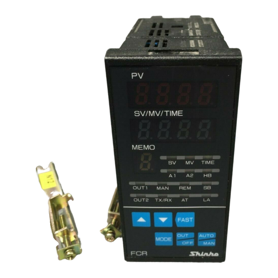
2 Name and Functions of Sections (11) (12) (13) (14) (15) (16) (10) (17) (Fig. 2-1) (1) PV display (Red) Indicates the PV or setting characters in the setting mode. (2) SV/MV/TIME display (Green) Indicates the SV, MV, Time or set values in each setting mode. (3) MEMO display (Yellow) Indicates the Set value memory number. - Page 11 (9) OUT2 indicator (Yellow) Lights when OUT2 (control output 2) is on. (For Direct current output type, flashes corresponding to the MV in 125ms cycles.) (10) TX/RX indicator (Green) Lights during Serial communication [TX (transmitting) output]. (11) A1 indicator (including Pattern end 1 output) (Red) Lights when the Alarm 1 (A1) output or Pattern end 1 output is on.
-
Page 12: Setup
(bottom of the instrument) while holding the instrument by the top and bottom. Latch Draw out the FCR-13A toward you by pushing the latch. (Fig. 3.1-1) 3.2 Switch Setting (Multi-function) - Page 13 The following items can be selected by the DIP switch (SW304). Default value: All switches OFF. (Table 3.2-1) Item SW304 Selection Switch status Fuzzy self-tuning PID control No.1: OFF No.2: OFF PID control No.1: ON No.2: OFF Control action PD control No.1: OFF No.2: ON ON/OFF control...
- Page 14 Select a sensor type using the Rotary switch (SW303) and DIP switch (SW304). Default value: K -200 to 1370 Note: If the input type is changed, Scaling high/low limit, External setting input high/low limit and transmission output high/low limit values (optional) will become the altered input range high/low limit value.
-
Page 15: Inserting The Internal Assembly
3.3 Inserting the Internal Assembly After the setup is completed, insert the internal assembly into the case. Firmly insert the assembly until it is locked by the latch at the bottom of the instrument. (There will be a clicking sound.) Caution Do not confuse the top and bottom of the internal assembly. -
Page 16: Panel Cutout (Scale: Mm)
4.3 Panel Cutout (Scale: mm) +0.5 n x 48-3 Lateral close mounting n: Number of units mounted +0.5 (Fig. 4.3-1) 4.4 Current Transformer (CT) Dimensions (Scale: mm) CTL-6S (for 20A) CTL-12-S36-10L1U (for 50A) (Fig. 4.4-1) -
Page 17: Mounting
Mountable panel thickness: 1 to 8mm. If Soft front cover (FC-R-S) is used, mounting panel thickness will be 1 to 7.5mm. Insert the FCR-13A from the front of the panel. Attach the mounting brackets to the slots at the top and bottom of the case, and secure the controller in place with the screws provided. -
Page 18: Wiring
5. Wiring Warning Turn the power supply to the instrument off before wiring or checking. Working on or touching the terminal with the power switched on may result in severe injury or death due to electric shock. Moreover, the instrument must be grounded before the power supply to the instrument is turned on. -
Page 19: Terminal Arrangement
5.1 Terminal Arrangement Ground [YA( )] EA or EV [YB( )] 100 to 240V AC or 24V AC/DC RS-232C (RS-485) OUT1 (R/M) OUT1 (S/M, A/M) W or W3 OUT2(DR)/A2/ P.END2/LA/P24 mA DC V DC TA or TV A1/P.END1 OUT2(DS,DA)/A2 /P.END2/LA/P24 (Fig. -
Page 20: Wiring Examples
Alarm unit Thermocouple Heater Electric furnace • The connectable SSRs in parallel are 2 units if the Shinko SSRs (SA-500 series) are used. • For a 24V AC/DC power source, do not confuse polarity when using direct current (DC). (Fig. 5.2-2) -
Page 21: Current Transformer 1(Ct1), 2(Ct2) Input Wiring (W/W3 Option)
5.2.1 Current Transformer 1 (CT1), 2 (CT2) Input Wiring (W/W3 Option) [Heater burnout alarm output] (1) This alarm is not usable for detecting current under phase control. (2) Use the current transformer (CT) provided, and pass one lead wire of heater circuit into the hole of the CT. -
Page 22: Settings
6. Settings Operation Flowchart Power ON (*1) (*1) Control output OFF function (Fixed value control) (approx. 1sec) Manual control (Fixed value control) PV/SV display mode (*1) Standby mode (Program control) (approx. 1sec) MV indication Remaining step time indication (*2) (approx. 3sec) (appprox. - Page 23 : Setting items with dotted lines are optional, and they appear only when the options are ordered. : This means that if the is pressed, the unit proceeds to the next setting item. : Press the key while holding down the key.
-
Page 24: Settings
6.2 Settings The PV display indicates the sensor characters selected in [Sensor input], and the SV/MV/TIME display indicates input range high limit (or Scaling high limit value for DC voltage, current inputs) for approx. 2 seconds (warm-up status) after power-on. See (Table 6.2-1). -
Page 25: Main Setting Mode
6.2.1 Main Setting Mode In the PV/SV display mode, if the key is pressed, the unit proceeds to the Main setting mode. The SV can be increased or decreased using the keys. If the key is pressed, the SV will be registered, and the controller will revert to the PV/SV display mode. -
Page 26: Integral Time
Character Name, Function, Setting range Default value Integral time 200 sec • Sets the integral time. Setting the value to 0 disables the function (PD control). • Not available if ON/OFF control or PD control is selected in [Control action]. •... -
Page 27: Heater Burnout Alarm Value
Character Name, Function, Setting range Default value Heater burnout alarm value 0.0A xx.x • Sets the heater current value for Heater burnout alarm. (xx.x: • Setting the value to 0.0 disables the function. Heater • Available only when Heater burnout alarm (W, W3 option) is ordered. current •... -
Page 28: Auxiliary Function Setting Mode
Since this function has no relation to the memory life, it is well suited when using with Shinko programmable controllers (with SVTC option). [About Lock 3] When using the FCR -13A as a Fixed value controller The data in the selected Set value memory number can be temporarily changed. -
Page 29: Sv High Limit
Character Name, Function, Setting range Default value SV high limit • Sets SV high limit value within the Scaling low limit value/Scaling high limit value range. • Setting range: SV low limit to Scaling high limit value (For DC input, the placement of the decimal point follows the selection.) SV low limit •... -
Page 30: Instrument Number
• Selects the communication protocol of this instrument. • Available only when the Serial communication (C, C5 option) is ordered • Selection item: : Shinko protocol : Modbus ASCII mode 6.2.4 Auxiliary Function Setting Mode 2 In the PV/SV display mode, if the key is pressed for approx. -
Page 31: Decimal Point Place
Character Name, Function, Setting range Default value No decimal Decimal point place point • Selects the decimal point place. • Not available if RTD or thermocouple is selected in [Sensor input]. : No decimal point • Selection item: : 1 digit after the decimal point : 2 digits after the decimal point : 3 digits after the decimal point PV filter time constant... -
Page 32: Out2 On/Off Hysteresis
Character Name, Function, Setting range Default value OUT2 ON/OFF hysteresis • Sets ON/OFF hysteresis for OUT2. • Not available if Heating/Cooling control (DR, DS, DA option) is not ordered, or if OUT2 is PID or PD control action. • Setting range: 0.1 to 100.0 ( ) A1 action Energized/De-energized Energized •... -
Page 33: External Setting Input High Limit
Character Name, Function, Setting range Default value External setting input high limit • Sets External setting input high limit value. For EA option (4 to 20mA), the value corresponds to 20mA input. • Available only when External setting (EA, EV option) is ordered. •... -
Page 34: Sv Fall Rate
Character Name, Function, Setting range Default value SV fall rate 0 /minute • Sets the SV fall rate (Falling value per minute). Setting the value to 0 or 0.0 disables the function. • Setting range: 0 to 9999 /min. With a decimal point: 0.0 to 999.9 /min. DC input: 0 to 9999 (The placement of the decimal point follows the selection.) Output status when input error... -
Page 35: Fixed Value Control/Program Control Switching
• The following shows the program pattern example. Set the step time to 00.00 for the unnecessary steps. [Program Example] Step number (Set value memory number) Step SV 1000 1000 OUT1 proportional band Integral time Derivative time OUT1 proportional cycle A1 value A2 value Step time... -
Page 36: Step 6 Time
Step 6 time 00.00 • Sets Step 6 time. (Available only for program control) • Setting range: 00.00 to 99.59 Step 7 time 00.00 • Sets Step 7 time. (Available only for program control) • Setting range: 00.00 to 99.59 6.2.6 Auto/Manual Control Switching MV can be changed manually. -
Page 37: Set Value Memory Function (Sm Option)
7. Set Value Memory Function (SM Option) If the SM option (Set value memory number external selection) is ordered, a maximum of 7 files (12 pieces of data per file) of data can be memorized. Control can be performed by selecting the desired file. One file comprises 12 kinds of data: SV, OUT1 proportional band, Integral time, Derivative time, OUT2 proportional band, A1 value, A2 value, Overlap/Dead band, OUT1 high limit value, OUT1 low limit value,... -
Page 38: Operation
After the controller is mounted to the control panel and wiring is completed, operate the unit following the procedures below. 8.1 When Using the FCR-13A as a Temperature Controller (1) Turn the power supply to the FCR-13A ON. For approx. 2 seconds after power-on, the sensor characters and the temperature unit... -
Page 39: When Using The Fcr-13A As A Simplified Programmable Controller
Instrument status when power is restored After restoration following a power failure during program control, the FCR-13A resumes program performance from where it stopped. (The PV display flashes until the step at which the power failure occurred is finished.) -
Page 40: Action Explanations
9 Action Explanations 9.1 OUT1 Standard Control Action Heating (reverse) action Cooling (direct) action Proportional band Proportional band Control action Cycle action is performed Cycle action is performed according to deviation. according to deviation. 12V DC 12/0V DC 0V DC 0V DC 0/12V DC 12V DC... -
Page 41: Out1 On/Off Control Action
9.3 OUT1 ON/OFF Control Action Heating (reverse) action Cooling (direct) action Hysteresis Hysteresis Control action 12V DC 0V DC 0V DC 12V DC 20mA DC 20mA DC 4mA DC 4mA DC Indicator (OUT1) Green Unlit Unlit : Turns ON (lit) or OFF (unlit). 9.4 Pattern End Action Pattern end Pattern end output is... -
Page 42: Heating/Cooling Control Action (Dr, Ds, Da Option)
9.5 Heating/Cooling Control Action (DR, DS, DA Option) 9.5.1 Heating/Cooling Control Action OUT1 P-band (OUT2 P-band) Heating (Cooling Control action action) action Cycle action is performed according to deviation. Cycle action is performed according to deviation. 12V DC 12/0V DC 0V DC Cycle action is performed according to deviation. -
Page 43: When Setting Dead Band
9.5.2 When Setting Dead Band OUT1 P-band Dead band (OUT2 P-band) Control Heating (Cooling action action action) Cycle action is performed according to deviation. Cycle action is performed according to deviation. 12V DC 12/0V DC 0V DC Cycle action is performed according to deviation. -
Page 44: When Setting Overlap Band With Relay Contact Output
9.5.3 When Setting Overlap Band with Relay Contact Output. OUT1 P-band OUT2 P-band Overlap band Control Heating (Cooling action action) action Cycle action is performed according to deviation. Cycle action is performed according to deviation. Indicator (OUT1) Green Unlit Indicator (OUT2) Yellow Unlit : Turns ON (lit) or OFF (unlit). -
Page 45: Alarm 1 (A1), Alarm 2 (A2) Action
9.6 Alarm 1 (A1), Alarm 2 (A2) Action High limit alarm Low limit alarm hysteresis hysteresis Alarm action -A1 value +A1 value -A1 value +A1 value +side +side Alarm output -side -side High/Low limit range alarm High/Low limits alarm hysteresis hysteresis Alarm action A1 value... - Page 46 High/Low limits alarm with standby High/Low limit range alarm with standby hysteresis hysteresis Alarm action A1 value A1 value A1 value A1 value Alarm output Process high alarm with standby Process low alarm with standby hysteresis hysteresis Alarm action A1 value A1 value Alarm output : A1 output terminals 9 and 10 are closed.
-
Page 47: Control Actions
10 Control Actions 10.1 Fuzzy Self-tuning Fuzzy self-tuning is a function that performs fine adjustment of PID values automatically. Stable control can be carried out even if the conditions of the production process are changed due to various external factors (types and rates of production). (1) When using the controller for the first time, perform the AT (auto-tuning) or set the proper PID values by keypad operation. -
Page 48: At Of This Controller
10.3 AT of This Controller In order to set each value of P, I and D automatically, the AT process has been made to fluctuate in order to achieve an optimal value. Sometimes the AT process will not fluctuate if AT is performed at or near room temperature. -
Page 49: Specifications
11 Specifications 11.1 Standard Specifications Mounting: Flush Mountable panel thickness: 1 to 3mm [If Soft front cover (FC-R-S) is used, 1 to 2.5mm] Setting: Input system using membrane sheet key Display: PV display: Red LED, 4 digits, character size, 8(H) x 4(W)mm SV/MV/TIME display: Green LED, 4 digits, character size, 8(H) x 4(W)mm MEMO display (Set value memory number): Yellow LED, 1 digit, character size, 8(H) x 4(W)mm... - Page 50 Alarm 1 output The alarm action point is set by the deviation from the SV (except Process alarm). [When A1 action Energized is selected] When the input goes outside the range, the output turns ON or OFF (in the case of High/Low limit range alarm).
- Page 51 ON/OFF control OUT1 ON/OFF hysteresis: Thermocouple, RTD input: 0.1 to 100.0 DC input: 1 to 1000 (The placement of the decimal point follows the selection.) Supply voltage: 100 to 240V AC, 50/60Hz, 24V AC/DC, 50/60Hz Allowable voltage fluctuation: 100 to 240V AC: 85 to 264V AC 24V AC/DC: 20 to 28V AC/DC Ambient temperature: 0 to 50...
- Page 52 Attached functions: [Control output OFF function], [Set value lock], [SV high/low limit] [Sensor correction], [Multi-range], [Multi-function], [Simplified programmable controller] [Burnout] When the thermocouple or RTD input is burnt out, OUT1 and OUT2 are turned off (for Direct current output type, OUT1, OUT2 low limit value), and the PV display flashes “...
- Page 53 [Self-diagnosis] The CPU is monitored by a watchdog timer, and when an abnormal status is found on the CPU, the controller is switched to warm-up status. [Automatic cold junction temperature compensation] (Thermocouple input type) This detects the temperature at the connecting terminal between thermocouple and the instrument, and always maintains it at the same status as if the reference junction temperature was at 0 (32 ).
-
Page 54: Optional Specifications
11.2 Optional Specifications Alarm 2 (Option code: A2) The alarm action point is set by the deviation from the SV (except Process alarm). [When A2 action Energized is selected] When the input goes outside the range, the output turns ON or OFF (in the case of High/Low limit range alarm). - Page 55 Data bit: 7 Parity: Even parity Stop bit: 1 Communication protocol: Shinko protocol, Modbus ASCII (Selectable by keypad) (When Modbus protocol is selected, the Digital external setting can not be used.) Digital external setting: Receives digital set value from Shinko Programmable controller PC-900, PCD-33A (with SVTC option).
- Page 56 Setting range: 20A: 0.0 to 20.0A (Indication: 0.0 to 50.0), 50A: 0.0 to 50.0A The alarm will be disabled when set to 0.0. Setting accuracy: Within 5% of heater rated current Action: ON/OFF action Output: Relay contact, 1a Control capacity: 3A 250V AC (resistive load) 1A 250V AC (inductive load, cos =0.4) Electrical life: 100,000 cycles Loop break alarm (Option code: LA)
-
Page 57: Troubleshooting
12 Troubleshooting If any malfunctions occur, refer to the following items after checking the power and the wiring. Warning Turn the power supply to the instrument off before wiring or checking. Working on or touching the terminal with the power switched on may result in severe injury or death due to electric shock. - Page 58 <Key operation> Problem Possible Cause and Solution The setting mode • Manual control is selected. cannot be selected. Change the mode to Automatic control. • Unable to set the SV, • Set value lock (Lock 1 or Lock 2) is selected. P, I, D, OUT1 Release the lock selection.
-
Page 59: Character Table
SV high limit SV low limit Sensor correction Overlap/Dead band Remote/Local setting Local Instrument number Communication speed 9600bps Communication protocol Shinko protocol <Auxiliary function setting mode 2> Character Item Default Data Scaling high limit value 1370 Scaling low limit value -200... - Page 60 • Serial number ----------------- No. 123F05000 In addition to the above, please let us know the details of the malfunction, if any, and the operating conditions. SHINKO TECHNOS CO., LTD. OVERSEAS DIVISION Head Office: 2-5-1, Senbahigashi, Minoo, Osaka, Japan http://www.shinko-technos.co.jp...
Need help?
Do you have a question about the FCR-13A and is the answer not in the manual?
Questions and answers