Table of Contents
Advertisement
Quick Links
Advertisement
Table of Contents

Related Manuals for Shinko FCR-13A


Summary of Contents for Shinko FCR-13A
- Page 1 MICROCOMPUTER BASED DIGITAL INDICATING CONTROLLER FCR-13A INSTRUCTION MANUAL...
- Page 2 • This instrument must be used under the conditions and environment described in this manual. Shinko Technos Co., Ltd. does not accept liability for any injury, loss of life or damage occurring due to the instrument being used under conditions not otherwise stated in this manual.
- Page 3 Caution • Use the solderless terminal with an insulation sleeve in which the M3 screw fits when wiring the FCR-13A. • The terminal block of this instrument is designed to be wired from the left side. The lead wire must be inserted from the left side of the terminal, and fastened with the terminal screw.
-
Page 4: Table Of Contents
CONTENTS 1. Model 1.1 Model ------------------------------------------------------------------------------ 6 1.2 Rated input ----------------------------------------------------------------------- 7 1.3 How to read the model label ------------------------------------------------- 7 2. Name and functions of the sections ------------------------------- 8 3. Setup 3.1 Taking the inner assembly out --------------------------------------------- 10 3.2 Switch setting (multi-function) --------------------------------------------- 10 3.3 Inserting the inner assembly ----------------------------------------------- 13 4. - Page 5 ----------------------- 34 8. Running 8.1 When using the FCR-13A as a Temperature controller ------------- 35 8.2 When using the FCR-13A as a Simplified program controller ----- 36 9. Action explanation 9.1 OUT1 action -------------------------------------------------------------------- 37 9.2 Heater burnout alarm action (option) ------------------------------------- 37 9.3 OUT1 ON/OFF action -------------------------------------------------------- 38...
-
Page 6: Model
1. Model 1.1 Model Control output (OUT1), input and option code, etc are entered where underlined. (e.g.) F C R – 1 3 A - R / M, A2 Alarm 2 (A2) output Multi-range input Relay contact output Standard specifications F C R –... -
Page 7: Rated Input
*: For DC input, input range and decimal point place can be changed. 1.3 How to read the model label Model labels are attached to the case and the inner assembly. Model label (e.g.) FCR-13A-R/M Relay contact output Alarm 2 (A2) output W (20A) Heater burnout alarm output (20A) -
Page 8: Name And Functions Of The Sections
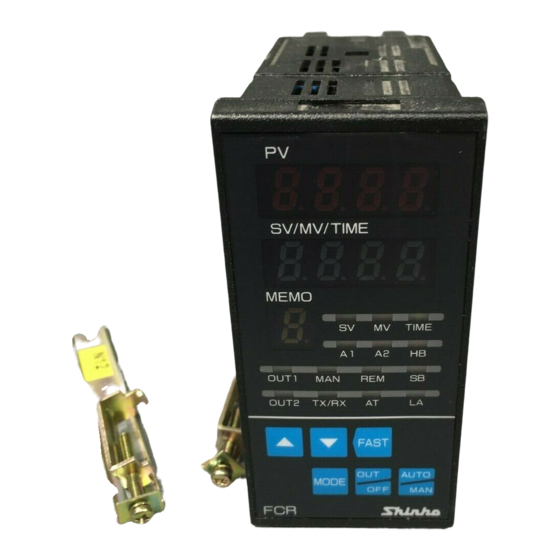
2. Name and functions of the sections (11) (12) (13) (14) (15) (16) (10) (17) (Fig. 2-1) (1) PV display Indicates the Process variable (PV) with a red LED. (2) SV/MV/TIME display Indicates the Main set value (SV), Manipulated variable (MV) or Time (TIME) with a green LED. - Page 9 (9) OUT2 indicator The yellow LED lights when OUT2 (Cooling output) is on. (For DC current output type, it flashes in 0.125 second cycles corresponding to the manipulated variable.) (10) TX/RX indicator A green LED lights during serial communication (TX, transmitting). (11) A1 indicator (including Pattern end 1 output) A red LED lights when the Alarm 1 (A1) output or Pattern end 1 output is on.
-
Page 10: Setup
(bottom of the instrument) in the direction indicated by the arrow while holding the instrument by the top and bottom. Latch Draw out the FCR-13A toward you by pushing the latch (Fig. 3.1-1) 3.2 Switch setting (multi-function) - Page 11 The following can be selected by the DIP switch (SW304). Default value: All switches OFF [ (Table 3.2-1) DIP SW Item Selection Switch status 304 No Fuzzy self-tuning PID action No.1: OFF No.2: OFF PID action No.1: ON No.2: OFF Control action PD action No.1: OFF...
- Page 12 Select a sensor type with a rotary switch (SW303). Default value: K (-200 to 1370 ) (Table 3.2-2) Rotary DIP SW. Sensor Scale range SW303 No. No. 7 -200 to 1370 -320 to 2500 -200 to 1000 -320 to 1800 0 to 1760 0 to 3200 0 to 1820...
-
Page 13: Inserting The Inner Assembly
3.3 Inserting the inner assembly If setup is completed, insert the internal assembly into the case. Firmly insert the assembly until it is locked by the latch at the bottom of the instrument. (There will be a clicking sound.) Caution Do not confuse the top and bottom of the internal assembly. -
Page 14: Panel Cutout
4.3 Panel cutout (Unit: mm) +0.5 n x 48-3 Lateral close mounting n: Number of units mounted +0.5 (Fig. 4.3-1) 4.4 CT (Current transformer) external dimensions (Unit: mm) CTL-6S (for 5A, 10A, 20A) CTL-12-S36-10L1 (for 50A) 2-M3 (Fig. 4.4-1) -
Page 15: Mounting
• When using the Screw type mounting bracket (BL option) Mounting panel thickness is within 1 to 15mm. Insert the FCR-13A from the front of the panel. Slot the mounting bracket to the holes at the top and bottom of the case, and screw in place. -
Page 16: Wiring
5. Wiring Warning Turn the power supply to the instrument off before wiring or checking. Working or touching the terminal with the power switched on may result in severe injury or death due to Electric Shock. Moreover, the instrument must be grounded before the power supply to the instrument is turned on. -
Page 17: Wiring Example
Lead wire solderless terminal Use a solderless terminal with an insulation sleeve in which an M3 screw fits as shown below. The torque should be 0.6N・m to 1.0N・m. Solderless Manufacturer Model name Tightening torque terminal Nichifu Terminal Industries CO.,LTD. 1.25Y-3 Y type 0.6N•m, Japan Solderless Terminal MFG CO.,LTD. - Page 18 Heater burnout alarm (1) This alarm is not usable for detecting current under phase control. (2) Use the current transformer (CT) provided, and pass one lead wire of heater circuit into the hole of the CT. (3) When wiring, keep CT wire away from AC sources and load wires to avoid the external interference.
- Page 19 [FCR-13A-R/E] 3-phase 100 to 240V AC Electro- magnetic Power supply switch for Alarm unit Alarm unit Thermocouple Heater Electric furnace (Fig. 5.2-4) * To prevent the unit from harmful effects of unexpected level noise, it is recommended that a surge absorber be installed between the electromagnetic switch coils.
-
Page 20: Operation
6. Operation The PV display indicates the sensor character selected during Sensor input selection and temperature unit, and the SV/MV/TIME display indicates the rated maximum value for approx. 2 seconds after the power is turned on. See (Table 6-1). During this time, all outputs and LED indicators are in OFF status. After that, control starts indicating the actual temperature on the PV display and SV on the SV/MV/TIME display. -
Page 21: Operation Flowchart
6.1 Operation flowchart Control output *1: Step remaining time can be indicated during program control. Approx.1sec) OFF function *2: If AT is performed, the controller reverts to the PV/SV display mode. If AT is cancelled, the mode goes to the “OUT1 proportional band”. PV/SV display *3: If is selected during “Program control”... -
Page 22: Main Setting Mode
6.2 Main setting mode If the key is pressed, the main setting mode is selected. key increase or decrease the set value (numeric value). Pressing the key registers the set value, and the controller will revert to the PV/SV display mode. SV [ ] •... -
Page 23: Integral Time Setting
Integral time setting [ ] • Sets the integral time. Setting the value to 0 disables the function (PD action). • Not available if ON/OFF action or PD action is selected during Control action selection (p.11) • Setting range: 0 to 3600 seconds •... -
Page 24: A2 Value Setting
A2 value setting [ • Sets the action point of A2 output. Setting the value to 0 or 0.0 disables the function. (Excluding process high alarm and process low alarm) • Not available when A2 output (option) is not added or if rotary switch is set to No.0 or No.7 during A2 type selection (p.12) even if it is added •... -
Page 25: Set Value Lock Selection
Since this function has no relation to the memory life, it is well suited when using with the Shinko programmable controllers with the SVTC option. • Default: Unlock [About Lock 3]... -
Page 26: Sensor Correction Setting
(4800bps), (9600bps), (19200bps) • Default: 9600bps Communication protocol selection [ • Selects the communication protocol of this instrument. • Available only when the Serial communication (option) is applied • Selection item: (Shinko protocol) (Modbus ASCII mode) • Default: Shinko protocol... -
Page 27: Scaling High Limit Setting
6.5 Auxiliary function setting mode 2 In the PV/SV display mode, if the key is pressed while holding down the keys for approx. 3 seconds, Auxiliary function setting mode 2 can be selected. key increase or decrease the set value (numeric value). Pressing the key registers the set value and switches to the next setting item. -
Page 28: Out2 Action Mode Selection
OUT2 action mode selection [ • Selects OUT2 cooling action from a choice of: Air cooling, oil cooling and water cooling. Available only when Heating/Cooling control (option) is added • Selection item: (Air cooling, linear characteristic) (Oil cooling, 1.5th power of the linear characteristic) (Water cooling, 2nd power of the linear characteristic) •... -
Page 29: A2 Hysteresis Setting
A2 hysteresis setting [ • Sets A2 hysteresis. • Not available if A2 (option) is not added or if the rotary switch is set to No.0 or No.7 during A2 type selection (p.12). • Setting range and default value are the same as those of A1 hysteresis setting. A1 action delayed timer setting [ •... -
Page 30: Transmission Output Low Limit Selection
Transmission output low limit selection [ • Sets the Transmission output low limit value. (For TA option, the value correponds to 4mA output.) • Available only when Transmission output (option) is added • Setting range: Input range low limit value to Transmission output high limit value •... -
Page 31: Control Output Off Function
[Energized/Deenergized] When alarm action Energized is selected, the alarm output (between terminals 7-8, or 9-10) is conducted (ON) while the alarm output indicator is lit. The alarm output is not conducted (OFF) while the alarm output indicator is not lit. See (Fig. -
Page 32: Output Mv And Step Remaining Time Indication
6.8 Output MV and Step remaining time indication Output MV (manipulated variable) indication In the PV/SV display mode, press the key for approx. 3 seconds. Keep pressing the key until the output manipulated variable appears, though the main setting mode appears temporarily during the process. For the fixed value control, when the key is pressed again, the mode reverts to the PV/SV display. - Page 33 In the PV/SV display mode, if the key is pressed while holding down the key for approx. 3 seconds, the Program mode can be selected. Program control [ • Either fixed value control or program control can be selected. • If the key is pressed in the fixed value control, the controller reverts to the PV/SV display mode.
-
Page 34: Set Value Memory Function (Sm Option)
To select the set value memory number (file number), connect the terminals between 13 to 16 as shown below (Table 7-1). Up to approx. 50 units of FCR-13A can be connected in parallel. Terminal connection for Set value memory number selection... -
Page 35: Running
After the controller is mounted to the control panel and wiring is completed, operate the unit following the procedures below. 8.1 When using the FCR-13A as a Temperature controller (1) Turn the power supply to the FCR-13A ON. For approx. 2sec after the power is switched ON, the sensor character and... -
Page 36: When Using The Fcr-13A As A Simplified Program Controller
. Instrument status after power is restored After restoration following a power failure during program control, the FCR-13A resumes program performance from where it stopped. The PV display flashes until the step at which the power failure occurred is finished. -
Page 37: Action Explanation
9. Action explanation 9.1 OUT1 action Heating (reverse) action Cooling (direct) action Proportional band Proportional band Control action SV setting SV setting Cycle action is performed Cycle action is performed according to deviation. according to deviation. 12V DC 12/0V DC 0V DC 0V DC 0/12V DC... -
Page 38: Out1 On/Off Action
9.3 OUT1 ON/OFF action Heating (reverse) action Cooling (direct) action Hysteresis Hysteresis Control action SV setting SV setting 12V DC 0V DC 0V DC 12V DC 20mA DC 20mA DC 4mA DC 4mA DC Indicator (OUT1) Green Unlit Unlit : Acts ON (lit) or OFF (unlit). 9.4 Pattern end action Pattern end action... -
Page 39: Out2 (Heating/Cooling Control) Action (Option)
9.5 OUT2 (Heating/Cooling control) action (Option) Heating P-band (Cooling P-band) Control Heaing (Cooling action action action) SV setting Cycle action is performed according to deviation. Cycle action is performed according to deviation. 12V DC 12/0V DC 0V DC Cycle action is performed according to deviation. - Page 40 When setting Dead band Heating P-band Dead band (Cooling P-band) Heatng (Cooling Control action action action) SV setting Cycle action is performed according to deviation. Cycle action is performed according to deviation. 12V DC 12/0V DC 0V DC Cycle action is performed according to deviation.
- Page 41 When setting Overlap band with Relay contact output. Heating P-band Cooling P-band Overlap band Heating (Cooling Control action action action) SV setting Cycle action is performed according to deviation. Cycle action is performed according to deviation. Indicator (OUT1) Green Unlit Indicator (OUT2) Yellow Unlit...
-
Page 42: Alarm 1 (A1) And Alarm 2 (A2) Action
9.6 Alarm 1 (A1) and Alarm 2 (A2) action High limit alarm Low limit alarm A1 hysteresis A1 hysteresis Alarm action + A1 + A1 set point set point set point setting setting set point + side + side Alarm output side side High/Low limits alarm... - Page 43 High/Low limits alarm with standby High/Low limit range alarm with standby A1 hysteresis A1 hysteresis Alarm action set point set point set point setting set point setting Alarm output Process high alarm with standby Process low alarm with standby A1 hysteresis A1 hysteresis Alarm action set point...
-
Page 44: Control Actions
10. Control actions 10.1 Fuzzy self-tuning Fuzzy self-tuning is a function to perform a fine adjustment of PID values automatically. The stable control can be carried out even if the conditions of the process are changed due to things like change in types and rates of production. (1) When the control initiates, the unit performs this function by the PID values previously adjusted. -
Page 45: Pid Auto-Tuning Of This Controller
10.3 PID auto-tuning of this controller In order to set each value of P, I, D and ARW automatically, the auto-tuning process should be made to fluctuate to obtain an optimal value. (A) In the case of a large difference between the SV and processing temperature as the temperature is rising. -
Page 46: Specifications
11. Specifications 11.1 Standard specifications Mounting : Flush Setting : Membrane sheet key Display PV display : Red LED display 4 digits, character size, 8(H) x 4(W)mm SV/MV/TIME display : Green LED display 4 digits, character size, 8(H) x 4(W)mm MEMO display : Yellow LED display 1 digit, character size, 8(H) x 4(W)mm Accuracy (setting, indication) - Page 47 Electric life: 100,000 times Non-contact voltage : For SSR drive V DC maximum 40mA DC(short circuit protected) If Shinko SSR (SA-200 series) is used, 4 units can be connected in parallel. Current : 4 to 20mA DC Load resistance, maximum 550...
- Page 48 Control action The fuzzy self-tuning PID, PID, PD or ON/OFF action can be selected by the DIP switch. • Fuzzy self-tuning PID action Proportional band (P) : Automatic Integral time (I) : Automatic Derivative time (D) : Automatic Anti-reset windup (ARW) : Automatic Proportional cycle : 1 to 120sec Output limiter...
- Page 49 Circuit insulation configuration Ground terminal Insulated Power source Insulated Insulated Insulated OUT1 output Communication (*2) Non-insulated Insulated (*1) Insulated Input OUT2 output, Transmission output A2 output or CT input LA output Non-insulated External setting Insulated input Set value memory number A1 output (*2) external selection...
- Page 50 [Input abnormality] Indication Contents OUT1 OUT2 Overscale OFF (4mA) or OFF(4mA) or Measured value " " flashes. OUT1 low limit OUT2 low limit has exceeded value value * Indication range high limit value. Underscale Measured value OFF (4mA) or OFF (4mA) or "...
-
Page 51: Optional Specifications
[Power failure countermeasure] The setting data is backed up in non-volatile IC memory. [Warm-up indication] For approx. 2 seconds after the power supply to the instrument is turned on, the input type and temperature unit are indicated on the PV display, and the input range high limit value (for DC input, scaling high limit value) is indicated on the SV display. - Page 52 Output : Relay contact 1a Control capacity, 3A 250V AC (resistive load) 1A 250V AC (inductive load cosø=0.4) Electric life: 100,000 times Heating/Cooling control (option code: DR, DS, DA) When Heating/Cooling control (option) is applied, A2 (option), LA (option), or Insulated power output (option) cannot be applied together.
- Page 53 Communication protocol Shinko protocol or Modbus ASCII mode (Selectable by keypad) Digital external setting Receives digital set value from Shinko programmable controllers such as PCD-33A (with SVTC option) or PC-900 series (with SVTC option). (Be sure to select Lock 3 during the Set value lock selection.) (When Modbus protocol ASCII mode is selected, digital external setting is not available.)
- Page 54 Heater burnout alarm (option code: W, W3) (Including sensor burnout alarm) Monitors the heater current with CT (current transformer), and detects the burnout. • If Heater burnout alarm is applied, the input sampling period will be 0.5 seconds. • This option cannot be applied to the DC current output type. Rating : 20A [Option W (20A), W3 (20A)] or 50A [Option W (50A), W3 (50A)]...
- Page 55 Dust-proof•Drip-proof (option code: IP) Dust-proof and Drip-proof specification (IP54) Effective for the face only, case is excluded. To protect the controller from water leak between control panel and controller, take note of the following items. (1) The panel cutout dimensions should be proper and have no burrs. (2) The control panel surface to be mounted should be vertical.
-
Page 56: Troubleshooting
12. Troubleshooting If any malfunctions occur, refer to the following items after checking the power and the wiring. Warning Turn the power supply to the instrument off before wiring or checking. Working or touching the terminal with the power switched on may result in severe injury or death due to Electric Shock. - Page 57 <Key operation> Problem Presumed cause and solution The setting mode • Manual control is selected. cannot be selected. Change the mode to Automatic control. (p.31) Settings (SV, P, I, D • Set value lock (Lock 1 or Lock 2) is selected. values, proportional Release the lock selection.
-
Page 58: Character Table
<Auxiliary function setting mode 1> Character Setting item Default value Data Set value lock - - - - (Unlock) SV high limit SV low limit Sensor correction Overlap band/Dead band Remote/Local switching : Local Instrument number Communication speed 9600bps Communication protocol : Shinko protocol... - Page 59 <Auxiliary function setting mode 2> Character Setting item Default value Data Scaling high limit 1370 Scaling low limit -200 Decimal point place No decimal point PV filter time constant 0.0 seconds OUT1 high limit 100% OUT1 low limit OUT1 ON/OFF action hysteresis OUT2 action mode selection Air cooling OUT2 high limit...
- Page 60 ***** Inquiry ***** For any inquiries about this unit, please contact the shop where you purchased the unit after checking the following. [Example] • Model --------------------------- FCR-13A-R/M • Type of input ------------------ K • Option --------------------------- A2, C5, W(20A) • Serial number ----------------- No.
Need help?
Do you have a question about the FCR-13A and is the answer not in the manual?
Questions and answers