Table of Contents
Advertisement
Quick Links
INSTRUCTION MANUAL (EXCERPT)
The digital indicating controller ACS-13A- /A is an exclusive instrument for use with the infrared temperature sensor
RD-500 series or RD-715-HA. For detailed usage and options, refer to the full Instruction manual for the ACS-13A
(standard product). Please download the full Instruction manual for ACS-13A at
Support & Downloads
The ACS-13A (standard product) has no infrared emissivity setting function, and its input types are different.
Thank you for purchasing our digital indicating controller ACS-13A- /A. This manual contains instructions for the
mounting, functions, operations and notes when operating the ACS-13A- /A. To prevent accidents arising from
the misuse of this controller, please ensure the operator receives this manual.
Safety Precautions
The safety precautions are classified into categories: "Warning" and "Caution".
Warning
: Procedures which may lead to dangerous conditions and cause death or serious injury, if not
carried out properly.
Caution
: Procedures which may lead to dangerous conditions and cause superficial to medium injury or
physical damage or may degrade or damage the product, if not carried out properly.
Warning
• To prevent an electric shock or fire, only Shinko or other qualified service personnel may handle the inner assembly.
•
To prevent an electric shock, fire or damage to the instrument, parts replacement may only be undertaken
by Shinko or other qualified service personnel.
Safety Precautions
• To ensure safe and correct use, thoroughly read and understand this manual before using this instrument.
• This instrument is intended to be used for industrial machinery, machine tools and measuring equipment. Verify
correct usage after purpose-of-use consultation with our agency or main office. (Never use this instrument for
medical purposes with which human lives are involved.)
• External protection devices such as protection equipment against excessive temperature rise, etc. must be
installed, as malfunction of this product could result in serious damage to the system or injury to personnel. Also
proper periodic maintenance is required.
• This instrument must be used under the conditions and environment described in this manual. Shinko Technos
Co., Ltd. does not accept liability for any injury, loss of life or damage occurring due to the instrument being used
under conditions not otherwise stated in this manual.
Caution with Respect to Export Trade Control Ordinance
To avoid this instrument from being used as a component in, or as being utilized in the manufacture of weapons of
mass destruction (i.e. military applications, military equipment, etc.), please investigate the end users and the final
use of this instrument. In the case of resale, ensure that this instrument is not illegally exported.
1. Model
ACS – 1 3 A
Control action
3
A1
Control output
(OUT1)
Input
Supply voltage
Option
(Multiple options are selectable.)
*1: Alarm types (9 types and No alarm action) and Energized/De-energized can be selected by keypad.
*2: Infrared temperature sensor RD-500 series or RD-715-HA is used for an input. Temperature range for
the sensor (0.0 to 250.0 , 0.0 to 500.0 *, 32.0 to 482.0 , 32.0 to 932.0 *) is selectable by keypad.
* For the RD-715-HA, ranges 0.0 to 500.0
*3: Supply voltage 100 to 240 V AC is standard. When ordering 24 V AC/DC, enter "1" after the input code.
Digital Indicating Controller
(For Use with the Infrared Temperature Sensor)
Downloads
(Be sure to read these precautions before using our products.)
/ A
,
A
R
S
A
A
1
A2
W(20A)
W(50A)
W3(20A)
W3(50A)
DR
DS
C5
SM
Manuals
Series name: ACS-13A- /A (W48 x H48 x D62 mm)
PID
Alarm type can be selected by keypad. *1
Relay contact: 1a
Non-contact voltage (for SSR drive): 12 V DC 15%
Direct current: 4 to 20 mA DC
Direct current: 4 to 20 mA DC *2
100 to 240 V AC (standard)
24 V AC/DC *3
Alarm 2 output (A2) *1
CT rated current: 20 A (Single-phase)
Heater
CT rated current: 50 A (Single-phase)
burnout
CT rated current: 20 A (3-phase)
alarm
CT rated current: 50 A (3-phase)
Heating/Cooling control,
Control output (OUT2)
Serial communication (RS-485)
Set value memory external selection
and 32.0 to 932.0
1
ACS-13A- /A
No.ACS11AE2 2017.04
http://www.shinko-technos.co.jp/e/
Relay contact: 1a
Non-contact voltage:12 V DC 15%
are available.
Advertisement
Table of Contents

Related Manuals for Shinko ACS-13A-*A Series


Summary of Contents for Shinko ACS-13A-*A Series
- Page 1 Warning • To prevent an electric shock or fire, only Shinko or other qualified service personnel may handle the inner assembly. • To prevent an electric shock, fire or damage to the instrument, parts replacement may only be undertaken by Shinko or other qualified service personnel.
-
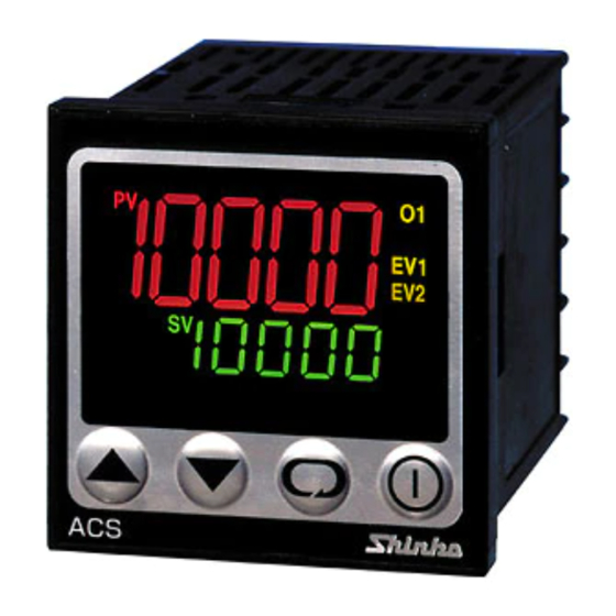
Page 2: Name And Functions
2. Name and Functions (1) PV indicator: Lights up when PV is indicated in PV/SV display mode. (2) PV display: Indicates the PV (process variable) or setting characters during setting mode. (3) SV indicator Lights up when SV is indicated in PV/SV display mode. (4) MEMO indicator: Lights up when the Set value memory external selection (SM option) is ordered. - Page 3 3.3 Panel Cutout (Scale: mm) Caution If horizontal close mounting is used for the controller, IP66 specifications (Drip-proof/Dust-proof) may be compromised, and all warranties will be invalidated. +0.5 n x 48-3 Lateral close mounting n: Number of units mounted (Fig. 3.3-1) +0.5 3.4 Mounting to and Removal from the Control Panel 3.4.1 How to Mount the ACS-13A- /A...
- Page 4 4.1 Terminal Arrangement • EV1: Alarm 1 output • EV2: Alarm 2 output (A2 option) or Heater burnout alarm output (W, W3 option) • O2: Control output (OUT2) (D option) • O1: Control output (OUT1) • DC: Direct current input (Infrared temperature sensor RD-500 series, or RD-715-HA) •...
-
Page 5: Operation Flow Chart
Infrared emissivity 0.200 to 1.000 -100.0 to 100.0 0 to 1000 sec Derivative time Communication protocol Infrared emissivity 2 : Shinko protocol 0.200 to 1.000 0 to 300 sec : Modbus ASCII : Modbus RTU Infrared emissivity 3 0.200 to 1.000... - Page 6 Characters Used in this Manual: Indication Number, Indication Alphabet Indication Alphabet [Infrared Emissivity Setting] If the surface temperature and controller indication value do not match in the high temperature range, control can be performed by adjusting the temperature to the desired level via the infrared emissivity setting. •...
- Page 7 PV display indicates setting item characters, and SV display indicates factory default. Setting items with dotted lines are optional, and they appear when the options are ordered. Key operation (Use the key to set or select each setting item.) • If the key is held down for 3 seconds at any setting mode, the unit will return to PV/SV display mode.
-
Page 8: Operation
1 piece [W (20 A) option], 2 pieces [W3 (20 A) option] CTL-12-S36-10L1U: 1 piece [W (50 A) option], 2 pieces [W3 (50 A) option] Accessories sold separately: Terminal cover SHINKO TECHNOS CO., LTD. OVERSEAS DIVISION Head Office: 2-5-1, Senbahigashi, Minoo, Osaka, Japan URL: http://www.shinko-technos.co.jp/e/...
Need help?
Do you have a question about the ACS-13A-*A Series and is the answer not in the manual?
Questions and answers