Table of Contents
Advertisement
Quick Links
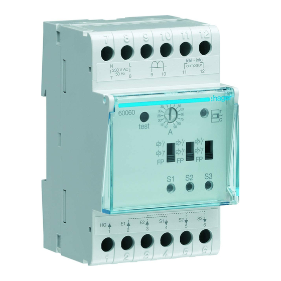
60060
z 3-output universal load controller
Operating principle
The 60060 load controller optimises your
electrical service. It manages excesses of
subscribed power, thereby helping you to keep
your electrical usage to a minimum.
It limits the power used by disrupting non-priority
circuits and prevents the branch circuit breaker
from being triggered. The 60060 is a universal
load controller.
It is suitable for all installations:
- single-phase and three-phase installations
equipped with an electronic counter
or
- single-phase installations equipped with
an electromechanical counter
It is adapted to circuit load-shedding via:
- closing switches
and/or
- opening switches
and/or
- pilot wire.
About the product
3
2
40 45
50
35
55
30
60
25
65
20
75
test
15
80
10
90
A
FP
FP
S1
S2
Counter indicator light:
1
- lit = counter connection correct
- flashing = no connection to counter
- off = no power.
Load-shedding threshold setting (for installati-
2
ons fitted with an electromechanical counter).
Test
button
3
Indicator lights for outputs 1, 2 and 3
4
- lit = the corresponding output is offloaded
- flashing = output error
(see What do I do if... ?) section.
Selection switch for output type
5
- installation with closing switch
- installation with opening switch
- installation with pilot wire.
1
Installation fitted with an
electronic counter
A 2-wire connection, the tele-information, connects
the load controller to the electronic counter. The
tele-information informs the load controller of any
exceedance of subscribed power in order to trigger
a load shedding cycle. This connection is not
polarized (max. distance = 100 m).
Use a 6/10 twisted pair cable.
Installation fitted with an
electromechanical counter
For this type of installation, the current
transformer that comes with the product
(part number 60005) must be connected to the
load controller.
This current transformer must be installed on the
phase that begins from the branch circuit breaker.
It informs the load controller of the total power
consumed by the installation.
When this consumption exceeds the limit set on
the load shedding threshold potentiometer, a
load shedding cycle is triggered.
1
Load shedding
The load controller is informed by the electronic
counter of the exceedance of subscribed power.
T
It will manage this excess as follows: all of
C
the channels are offloaded. It then relays the
channels in the following order of priority:
1. the outputs in "contact" mode or the pilot wire
outputs that are set to "comfort"
FP
2. the pilot wire outputs that are set to "reduced"
3. the pilot wire outputs that are set to "frost
S3
protection".
FP
It will perform a rotating load shed between the
outputs that have the same priority level.
The load shedding cycle is 6 minutes.
4
5
Configuring the output type
FP
The switches
FP
FP
FP
FP
FP
5
define the type of output.
•
outputs in "closing switch" mode.
To be used when the outputs
control a closing switch (C or NO).
In this mode:
- Load shedding = Off = 0 V
- On = 230 V
•
outputs in "opening switch" mode.
To be used when the outputs
control an opening switch (O or
NC).
In this mode:
- Load shedding = Off = 230 V
- On = 0 V
•
outputs in "pilot wire" mode. To
be used when the outputs control
pilot wire input devices.
In this mode:
- Load shedding = "off" signal.
- 6 compatible pilot wire sequences.
Test button
Pressing this button launches a load shedding
test. This test consists of gradually offloading
outputs 1, 2 and 3 over 30 seconds.
The LEDs flash 5 times to indicate that test mode
is now in progress, then the LED corresponding
to the offloaded channel lights up.
At the end of the test, all of the LEDs switch off.
In pilot wire mode, load shedding is taken to
be the sending of a "stop" signal, which is
understood by all of the devices equipped with a
pilot wire input.
The outputs are compatible with 6 pilot wire
sequences.
Frost protection input
(terminal 1)
This input allows you to force the pilot wire
outputs in frost protection mode. You can
connect a switch, the output of your telephone
controller, etc.
G
This input only operates in "pilot wire" mode.
Programming inputs
(terminals 2 and 3)
Input E1 (terminal 2) controls
output S1 (terminal 4).
Input E2 (terminal 3) controls
outputs S2 and S3 (terminals 5 and 6).
•
In pilot wire mode: using these inputs, you can
connect a heating timer via the pilot wire.
•
Whatever the timer instructions, the load
shedding sequence takes priority.
•
In contactor mode: these inputs
allow you to force OFF
Position of switch
5
Input
230 V
Closing switch
Opening switch
0 V
Closing switch
Opening switch
What to do if... ?
•
One or more "output" indicator lights are flashing:
- there is a short circuit on the output (pilot
wire/phase inversion in a convector, for
example).
- There is overconsumption on this output:
check how many devices are connected
to this output and their consumption.
Call your electrician.
•
The counter indicator light is flashing:
- the tele-information link is not active, check
the connection or call your power company.
Installation fitted with an electromechanical
counter: this operation is normal.
Technical features
Power supply:
230 V~ +10/-15% 50 Hz
Power consumption:
- in contact mode:
1 A/230 V~ upon call
so, for example,10 x 25 A contactors
(2 modules) for 3 outputs.
- in pilot wire mode:
60 mA/230 V~ per output.
Load shedding cycle:
Operating temperature:
Storage temperature:
Protection rating:
Connection capacity:
flexible: 1 to 6 mm
rigid: 1.5 to 10 mm
Outputs 1.2
and 3
Off = 0 V
Off = 230 V
On = 230 V
On = 0 V
< 10 W
Break capacity:
6 minutes
0°C to +50°C
-20 °C to +60 °C
IP 20
2
2
6LE007129A
Advertisement
Table of Contents

Related Manuals for hager 60060


Summary of Contents for hager 60060
- Page 1 This connection is not • Whatever the timer instructions, the load from being triggered. The 60060 is a universal polarized (max. distance = 100 m). shedding sequence takes priority. load controller.
- Page 2 1 circuit 1 normally closed) Directive 2014/53/EU. (borne repos) The CE declaration is available on the: www.hagergroup.com Hager Controls S.A.S., 33 rue Saint-Nicolas, B.P. 10140, 67703 SAVERNE CEDEX, France - www.hager.com Hager 08.19 - 6LE007129A...
Need help?
Do you have a question about the 60060 and is the answer not in the manual?
Questions and answers