
Related Manuals for Omron NS12-TS00


Summary of Contents for Omron NS12-TS00
- Page 1 Cat. No. V072-E1-02 NS-Series NS12-TS00@, NS12-TS01@ NS10-TV00@, NS10-TV01@ NS7-SV00@, NS7-SV01@ Programmable Terminals SETUP MANUAL...
- Page 2 OMRON. No patent liability is assumed with respect to the use of the information contained herein. Moreover, because OMRON is constantly striving to improve its high-quality products, the information contained in this manual is subject to change without notice.
-
Page 3: Table Of Contents
Contents Notice ..............................1 About this Manual ..........................6 Related Manuals ..........................7 Terminology ............................8 Introduction ............................9 Section 1 Overview 1-1 NS-series PT Functions and Operation....................1-2 1-1-1 PT Functions for FA Manufacturing Sites ................1-2 1-1-2 NS-series PT Operating System................... 1-3 1-2 Communications with the Host......................1-5 1-2-1 What is an NT Link?...................... - Page 4 3-5-2 Using the Board ......................... 3-17 3-6 Using Memory Cards........................3-18 3-6-1 Installation.......................... 3-19 3-6-2 Replacing System Programs ....................3-20 3-6-3 Transferring Data with Memory Cards ................3-20 3-7 Installing the Video Input Unit ......................3-27 3-7-1 Video Input Unit Components ................... 3-27 3-7-2 Nomenclature and Functions....................
- Page 5 6-3 PT Operating Settings........................6-15 6-3-1 Start-up Wait Time......................6-16 6-3-2 Screen Saver........................6-16 6-3-3 Key Press Sound ........................ 6-17 6-3-4 Buzzer Sound ........................6-17 6-3-5 Backlight ..........................6-18 6-3-6 Calendar Check ........................6-18 6-3-7 Contrast (NS7 Only) ......................6-19 6-4 Project Settings ..........................
- Page 6 Section 7 Maintenance and Troubleshooting 7-1 Maintenance............................7-2 7-1-1 Replacing the Battery......................7-2 7-2 Inspection and Cleaning........................7-5 7-3 Troubleshooting and Maintenance..................... 7-7 7-4 Requesting a Replacement PT ......................7-13 Appendices Appendix 1 Quick Reference .......................A-2 Appendix 2 Specifications ........................A-3 Appendix 3 Dimensions........................A-10 Appendix 4...
-
Page 7: About This Manual
About this Manual Section 1 Overview This section provides an overview of the NS-series PTs, including functions, features, connection types, and communications methods. Section 2 Before Connecting This section provides information on methods for connecting NS-series PTs that must be understood before connecting the host and peripheral devices. -
Page 8: Related Manuals
Related Manuals The following manuals are used for NS-series PTs. (The boxes at the end of the catalog numbers indicate the revision code.) NS Series Setup Manual ............V072-E1-@ This manual Describes how to connect the PT to the host and peripheral devices, methods to setup communications and operation, and procedures for maintenance. -
Page 9: Terminology
Board PLC. Communications Board Indicates a Communications Board for an OMRON C200HX/HG/HE(-Z) PLC. CPU Unit Indicates a CPU Unit in the OMRON SYSMAC CS/CJ, C, or CVM1/CV Series of Programmable Controllers. NS-Designer Indicates the OMRON NS-Designer (NS-NSDC1-V@ ). Host Indicates the PLC, IBM PC/AT or compatible computer, or personal computer functioning as the control device and interfaced with the NS-series PT. -
Page 10: Introduction
OMRON representative. • Make sure that the ratings and performance characteristics of the product are sufficient for the systems, machines, and equipment, and be sure to provide the systems, machines, and equipment with double safety mechanisms. - Page 11 Section 1 Overview This section provides an overview of the NS-series PTs, including functions, features, connec- tion types, and communications methods. 1-1NS-series PT Functions and Operation................1-2 1-1-1 PT Functions for FA Manufacturing Sites..............1-2 1-1-2 NS-series PT Operating System ................1-3 1-2Communications with the Host....................
-
Page 12: Ns-Series Pt Functions And Operation
1-1 NS-series PT Functions and Operation 1-1 NS-series PT Functions and Operation The NS Series offers advanced operator interfaces called Programmable Terminals that can be used to display required information and provide operating capabilities for FA manufac- turing sites. This section describes the role and functions of the NS-series PTs for first-time users of Programmable Terminals. -
Page 13: Ns-Series Pt Operating System
1-1 NS-series PT Functions and Operation @ Control Panel Switches The NS-series PTs allow the user to create various on-screen switches. By using touch switch inputs, operating results can be sent to the host. 1-1-2 NS-series PT Operating System @ Transferring Screen Data The screen data displayed on NS-series PTs is created using the NS-Designer on a com- puter and transferred to the PT through RS-232C or Ethernet communications. - Page 14 1-1 NS-series PT Functions and Operation @ Displaying Screens The information displayed on the screens is created using the NS-Designer on a computer and transferred to the PT. The required screens can be displayed by using commands from the host or touch switch operations. Host The required screens can be displayed by using...
-
Page 15: Communications With The Host
1-2 Communications with the Host 1-2 Communications with the Host NS-series PTs allow the user to allocate words and bits in any PLC area for use in accessing the required display contents and storing input data. Operations that can be performed include reading and writing allocated word contents and bit status directly, changing the display status of functional objects on the PT screen, and controlling and notifying PT status. -
Page 16: What Is An Nt Link
1-2-1 What is an NT Link? An NT Link is a method for high-speed communications with OMRON PLCs using a special protocol. The following PLCs can be connected using NT Link communications. CPM1A, CPM2A, CPM2C, CQM1, CQM1H, C200HS, C200HX/HG/HE (-Z),... -
Page 17: System Configuration
• Recommended Bar Code Reader (Refer to page 3-12.) OMRON V520-RH21-6 • Expansion Memory Board (Refer to page 3-15.) OMRON NS-MF081 (8-MB flash memory) OMRON NS-MF161 (16-MB flash memory) • RS-232C/422A Converter OMRON NS-AL002 (non-insulated) (Refer to page A-13.) OMRON NT-AL001 (insulated) - Page 18 1-3 System Configuration • Recommended Memory Cards (Refer to page 3-18.) OMRON HMC-EF172 (15-MB flash memory) OMRON HMC-EF372 (30-MB flash memory) OMRON HMC-EF672 (64-MB flash memory) • NS-Designer (Refer to NS-Designer Operation Manual (V074-E1-@) NS-NSDC1-V@ (CD-ROM version) Reference The following optional products are available. (Refer to page A-34.)
-
Page 19: Procedure For Running Ns-Series Pts
1-4 Procedure for Running NS-series PTs 1-4 Procedure for Running NS-series PTs Use the following procedure to start up the NS-series system. Host NS-Designer Host settings Panel installation Installation on the computer Refer to page 3-4. Refer to following pages. Refer to NS-Designer Peripheral connections 1:1 NT Link: 4-2 and A-7... - Page 20 1-4 Procedure for Running NS-series PTs The following table lists the device and software manuals used for reference. Device/Software Manual name Catalog No. NS-series PTs Programming Manual V073 Macro Reference Provided with NS- Designer Tutorial Provided with NS- Designer NS-Designer NS-Designer Operation Manual V074 NS-series Ladder...
-
Page 21: Section 2 Before Connecting
Section 2 Before Connecting This section provides information on methods for connecting NS-series PTs that must be under- stood before connecting the host and peripheral devices. 2-1Connecting the Host ......................2-2 2-1-1 Communications Types and Connection Methods ........... 2-2 2-2Part Names and Functions ....................2-7... -
Page 22: Connecting The Host
1:N NT Links + 1:N NT Links Not supported. • Converting Communications Type Using RS-232C/RS-422A Converter OMRON’s NS-AL002 RS-232C/RS-422A Converter can be used to convert the communica- tions type between RS-232C and RS-422A. • Communications Type and Connection Method Combinations... - Page 23 2-1 Connecting the Host 1:1 Connection Supported communications Host Refer- methods commu- commu- Supported connection methods ence nications nications 1:1 NT 1:N NT Data page FINS type type Link Links Links Host P.4-2 RS-232C P.4-10 RS-232C cable RS-232C Host NS-AL002 P.4-2 RS-422A Converter...
- Page 24 2-1 Connecting the Host 1:N Connection (Connecting Multiple PTs to a Single Host) Supported communications Host Refer- methods commu- commu- Supported connection methods ence nications nications 1:1 NT 1:N NT Data page FINS type type Link Links Links Host NS-AL002 Adapter RS-422A cable RS-232C RS-422A...
- Page 25 2-1 Connecting the Host N:1 Connection (Connecting Multiple Hosts to a Single PT) Host Supported communications com- methods Refer- commu- munica- Supported connection methods ence nications 1:1 NT 1:N NT Data tions page FINS type Link Links Links type P.4-2 P.4-10 Host Serial port A...
- Page 26 2-1 Connecting the Host Host Supported communications com- methods Refer- commu- munica- Supported connection methods ence nications 1:1 NT 1:N NT Data tions page FINS type Link Links Links type Host RS-232C, P.4-2 232C, Serial port A Controller P.4-10 Control- RS-232C cable Controller Link Link...
-
Page 27: Part Names And Functions
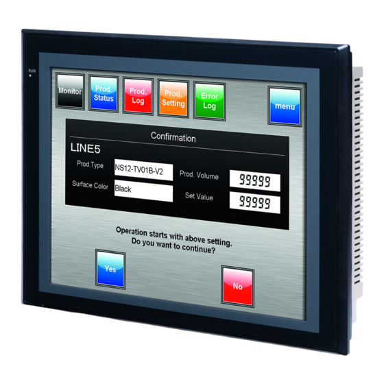
2-2 Part Names and Functions 2-2 Part Names and Functions The part names and functions of the PT are described here. NS12/NS10 Front Panel RUN indicator Display Lights or flashes to indicate NS12: 12.1-inch TFT high-luminance LCD the status of the PT. NS10: 10.4-inch TFT high-luminance LCD The entire display is a touch panel that serves as an input device. - Page 28 2-2 Part Names and Functions NS12/NS10 Rear Panel Switches Reset Switch Used to initialize the PT. The status of screen data, other registered data, and memory switches, however, will not change. Expansion Memory Board Cover Used to expand the screen data. Open the cover and install the Expansion Memory Board in the slot.
- Page 29 2-2 Part Names and Functions NS7 Front Panel Display RUN indicator 7.7-inch color STN LCD Lights or flashes to indicate the The entire display is a touch status of the PT. panel that serves as an input device. RUN Indicator Status Indicator Green Orange...
- Page 30 2-2 Part Names and Functions NS7 Rear Panel Reset Switch Used to initialize the PT. The DIP Switch statuses of screen data, other Used to set the settings for registered data, and memory transferring data using the memory switches will not change. card.
- Page 31 2-2 Part Names and Functions Touch Panel The touch switches on the front panel of the PT are used to perform input operations. Press the touch switches to perform operations such as switching screens and sending bit status to the host. Minimum Switch Size 16 dots (4.92 mm) ×...
- Page 32 2-2 Part Names and Functions Connector Pin Arrangement of Serial Ports A and B Pin number Signal name Name Not connected. Send data Receive data Request to send Clear to send 5-V output (250 mA max.) Not connected. Not connected. Signal ground Note Make sure that the total current capacity of devices being supplied power is 250 mA max.
- Page 33 Section 3 Installing the PT and Connecting Peripheral Devices This section describes the methods used to install the PT and connect peripheral devices. For details on methods for connecting the host, refer to Section 4 Connecting the Host to the Se- rial Port or Section 5 Connecting to Host via Ethernet or Controller Link.
- Page 34 3-1 Installing the PT 3-7-3 Installation Method for Video Input Unit ............... 3-29 3-7-4 Connecting to Video Input Connectors..............3-34 3-8 Installing the Controller Link Interface Unit..............3-39 3-8-1 Controller Link Interface Unit Components ............3-39 3-8-2 Nomenclature and Functions .................. 3-40 3-8-3 Installation Method for Controller Link Interface Unit ..........
-
Page 35: Installing The Pt
3-1 Installing the PT Note When unpacking the PT and peripheral devices, check for any external damage. Shake the product gently and check for any abnormal sounds. 3-1 Installing the PT The methods used to mount the PT to the control panel and connect the power supply are described here. -
Page 36: Installing Expansion Memory Boards And Rs-232C/Rs-422A Converters
3-1 Installing the PT 3-1-2 Installing Expansion Memory Boards and RS-232C/RS-422A Converters When using Expansion Memory Boards or Adapters, mount the PT to the control panel be- fore installing these Units. For details on installing and removing Expansion Memory Boards, refer to 3-5 Using Expan- sion Memory Boards. -
Page 37: Connecting The Power Supply
3-1 Installing the PT 2. Secure the panel mounting brackets from the back of the panel, as shown in the following diagram. Insert the catch on each bracket into the square hole on the PT, and secure the PT to the panel by tightening the screws with a Phillips screwdriver while gently pulling in the PT. -
Page 38: Wiring The Ground Wire
3-1 Installing the PT · Parts Used to Connect the Power Supply Note Connect power to the power terminal block using twisted-pair power lines with a cross- sectional area of at least 2 mm and always using M3.5 crimp terminals. The correct tightening torque for the terminal block is 0.8 N×m. -
Page 39: Starting The Pt
Indicator lights green. When the system starts properly, the indicator will light green. If the indicator does not light green, the system programs may be damaged. Contact your nearest OMRON representative. ¯ Startup message is displayed. A message about the startup status will be displayed. - Page 40 3-2 Starting the PT ¯ PT starts operating The PT goes into RUN mode and starts operating according to the screen data in the PT. When the PT is connected using communications conditions other than the set conditions, a message “Connecting…” will be displayed at the bottom right of the screen, and the PT will be in standby status until normal connection is established.
-
Page 41: Starting The Pt For The First Time
3-2 Starting the PT 3-2-2 Starting the PT for the First Time Always perform the following operations when turning ON the PT for the first time after pur- chase. 1. Language selection. 2. Format the screen data area. 3. Set the date and time. Operate according to the following conditions. - Page 42 3-2 Starting the PT f) Next, select the PT Tab. Set the time and date. g) Press the date display area under the heading Date and Time. A dialog box will be displayed. Input the date in yyyy/mm/dd format. Example: Input March 15, 2002 as 2002.3.15. h) Press the time display area under the heading Date and Time.
-
Page 43: Connecting The Ns-Designer
· Recommended Connecting Cables Use the following cables when connecting via RS-232C. XW2Z-S002 (OMRON, cable length: 2 m) (D-Sub male 9-pin and D-Sub female 9-pin, for IBM PC/AT or compatible computers and NX computers in the PC-9800 Series) For details on preparing connecting cables, refer to Appendix 4 Preparing Connecting Ca- bles. -
Page 44: Connecting To Bar Code Readers
(RS-232C, 9-pin) Connecting cable Bar Code Reader cable Recommended Bar Code Reader: V520-RH21-6, manufactured by OMRON. Note Always turn OFF the power to the Bar Code Reader and the PT before connecting or discon- necting cables. Prepare the connecting cables, referring to Appendix 7 Preparing Connecting Cables for Bar Code Readers. -
Page 45: Setting Bar Code Readers
3-4 Connecting to Bar Code Readers 3-4-2 Setting Bar Code Readers The Bar Code Reader’s communications conditions and other settings can be set from either the NS-Designer or the PT. @ Setting from the NS-Designer Use the NS-Designer to set PT settings, such as the conditions for communications with the Bar Code Reader, according to the following table. -
Page 46: Data Format
3-4 Connecting to Bar Code Readers 3-4-3 Data Format Use the following data format for communications using the PT’s bar code input function. Data Data Data The supported data characters are 20 to 7F hexadecimal and the maximum data length is 40 bytes. -
Page 47: Using Expansion Memory Boards
3-5 Using Expansion Memory Boards 3-5 Using Expansion Memory Boards This section provides details on Expansion Memory Boards that are used with NS-series PTs. When using the NS10 or NS12, the volume of screen data can be increased by installing an Expansion Memory Board in the PT. -
Page 48: Installation Procedure
3-5 Using Expansion Memory Boards 3-5-1 Installation Procedure Use the following procedure to install the Expansion Memory Board. 1. Turn OFF the power to the PT. 2. Remove the cover of the Expansion Memory Connector at the top of the PT rear panel by sliding it upwards. -
Page 49: Using The Board
3-5 Using Expansion Memory Boards 3-5-2 Using the Board After installing the Expansion Memory Board in the PT, initialize (format) the Expansion Memory Board. The PT settings do not require changing. When transferring more than 4 Mbytes of data to the PT, the data is also transferred automatically to the Expansion Mem- ory Board. -
Page 50: Using Memory Cards
3-6 Using Memory Cards 3-6 Using Memory Cards 1. Memory Cards can be used with the PT. History files can be stored in Memory Cards as CSV files. There are four different types of history file, as follows: Alarm/event history: Stores alarm/event history data that has been registered by NS-Designer. -
Page 51: Installation
3-6 Using Memory Cards 3-6-1 Installation The Memory Card is installed in the memory card interface on the side of the PT. Front surface Eject button Eject button Enlarged view after installation Push the Memory Card firmly into the back of the slot. (The eject button will be pushed out when the Memory Card is installed properly.) ·... -
Page 52: Replacing System Programs
Replacing System Programs When the system programs are loaded with the NS-Designer, they are stored under the NS- Designer’s install folder (default location is C:\Program Files\Omron\NS-Designer-V2) in fold- ers that are created for each type and version, as follows: \SystemProgram\NS12\V3_0x\bank1: Ver. 3.0x for NS12 \NS10\V3_0x\bank1: Ver. - Page 53 3-6 Using Memory Cards @ DIP Switch The Memory Card can be divided into up to four areas, which are called banks. The DIP switch on the rear panel of the PT has eight pins. The ON/OFF combination of these pins specifies which transfer method is used.
- Page 54 3-6 Using Memory Cards @ Automatic Download An automatic download transfers system programs and screen data from the Memory Card to the PT. Set the DIP switch for automatic download, as shown below. The Memory Card cannot be used to transfer data when the DIP switch pins are set to com- binations other than those specified here.
- Page 55 3-6 Using Memory Cards @ Automatic Upload An automatic upload transfers system programs and screen data from the PT to the Memory Card. Set the DIP switch for automatic upload, as shown below. The Memory Card cannot be used to transfer data when the DIP switch pins are set to com- binations other than those specified here.
- Page 56 3-6 Using Memory Cards @ Manual Transfer Use screen operations to select the direction (download, upload), contents (project, project and system, or system), and banks. Set pin 6 of the DIP switch to ON for manual transfer. DIP switch pin and status Operation Manually downloads or uploads system programs and screen data.
- Page 57 3-6 Using Memory Cards @ Errors · During Automatic Transfer The indicator on the front panel will flash red if an error occurs during data transfer. Check the following items if an error occurs. · Is the Memory Card inserted into the PT? ·...
- Page 58 Refer to the How to update or recover the system program (PDF) for details on recovery operations. This can be started from Windows Start – Programs – Omron – NS- Designer Ver. 3.0. 3. The system will start automatically downloading data from bank 1 of the Memory Card to the PT.
-
Page 59: Installing The Video Input Unit
3-7 Installing the Video Input Unit Installing the Video Input Unit A Video Input Unit (NS-CA001) can be mounted to an NS-series PT. Mounting a Video Input Unit allows images from a video camera or vision sensor to be displayed on the PT screen. This section explains how to connect a Video Input Unit to the PT with a cable. -
Page 60: Nomenclature And Functions
Four Video Input Connectors BNC connectors for inputting NTSC/PAL Console Port Connector signals. Connects to the console connector of OMRON Vision Sensors and allows Vision Sensor settings to be performed from the PT. Video Board: Rear View Expansion Interface Connector Connects to the PT's expansion interface connector when mounting the Video Board. -
Page 61: Installation Method For Video Input Unit
3-7 Installing the Video Input Unit 3-7-3 Installation Method for Video Input Unit This section describes the method for mounting the Video Input Unit to the PT. The Video In- put Unit can be mounted to NS12 and NS10 PTs only. It cannot be mounted to an NS7 PT. ·... - Page 62 3-7 Installing the Video Input Unit 2. Secure the four corners of the Video Board with screws. Secure these four places with screws. 3. Insert screws in the screw holes for attaching the cover and tighten them slightly. Insert the screws first. Align the cover’s screw holes with the screws and mount the cover.
- Page 63 3-7 Installing the Video Input Unit Slide the cover downward and tighten the screws. Slide the cover Mount the cover. Tighten the screws. ● Connecting the Cable Connect the functional ground terminal of the PT and the cover with the cable to prevent malfunction due to noise.
- Page 64 3-7 Installing the Video Input Unit ● Removing the Video Input Unit 1. Remove the cover from the PT as follows: Loosen the screws. Lift up on the cover and remove it. Lift up on the cover and remove it. 2.
- Page 65 3-7 Installing the Video Input Unit 3. Remove the Video Board from the expansion interface connector of PT. Follow the procedure shown below. Remove the upper side of Video Board first, holding the four corners. Then, pull out the entire Video Board.
-
Page 66: Connecting To Video Input Connectors
3-7 Installing the Video Input Unit 3-7-4 Connecting to Video Input Connectors Use the following method to connect cameras to the Video Input Unit mounted to the PT. Note The tensile load of the cable is 30 N maximum. Do not exceed maximum load. ●... - Page 67 3-7 Installing the Video Input Unit ● Removing the Video Input Connector 1. Unlock the BNC socket on the camera’s video output cable by twisting it counterclock- wise while pushing it. Push Twist counterclockwise 2. After unlocking the BNC socket, pull it out. Pull out 3-35...
- Page 68 BNC-RCA connector in the way shown below. Video input connector (BNC type) BNC-RCA connector (See note.) RCA plug Note A BNC-RCA connector is provided with the Monitor Cable (F150-VM) for OMRON Vision Sen- sors. It is not provided with the Video Input Unit (NS-CA001). 3-36...
- Page 69 ●Connecting to the Console Port Connector Use the following method to connect the Video Board’s console port connector to the console connector of an OMRON Vision Sensor (F150-C10V3, F160-C10, F180-C10, F400-C10V2, F250-C10, V530-R150V2). 1. Insert the socket of the Relay Cable (F150-VKP; see note) into the Video Board’s console port connector.
- Page 70 3-7 Installing the Video Input Unit ● Setting the Contrast If the picture displayed on the PT screen is too bright or dark, contrast adjustment is required. Contrast adjustment is usually performed using one of the following procedures. · Select Video Configuration from the Special Screen Tab Page in the System Menu. (Refer to Video Configuration under 2-18 Special Functions in the NS-series Programmable Ter- minals Programming Manual.) ·...
-
Page 71: Installing The Controller Link Interface Unit
3-8 Installing the Controller Link Interface Unit Installing the Controller Link Interface Unit This section describes the method for installing and wiring the Controller Link Interface Unit. It can be mounted to NS12 and NS10 PTs only. It cannot be mounted to an NS7 PT. 3-8-1 Controller Link Interface Unit Components The following table shows the Controller Link Interface Unit’s product configuration. -
Page 72: Nomenclature And Functions
3-8 Installing the Controller Link Interface Unit 3-8-2 Nomenclature and Functions Familiarize yourself with the nomenclature and functions of the Controller Link Support Board before operation. Interrupt shorting Pin Memory Allocation Switch Set at the factory. Do not Set at the factory. Do not change change the factory setting. - Page 73 3-8 Installing the Controller Link Interface Unit ● Indicators Indicator Name Color status Meaning Operating Normal operation. Green Not lit A Board operating error (watchdog timer error) occurred. Communications Red Lit One of the following errors occurred. error • Communications error •...
- Page 74 3-8 Installing the Controller Link Interface Unit ●Switch Settings The following settings are made at the factory. Do not change these settings. Item Switch Setting Memory address Memory allocation switch SW1: ON SW2: ON SW3: OFF SW4: ON Interrupt level Interrupt shorting pin Set to IRQ10.
-
Page 75: Installation Method For Controller Link Interface Unit
3-8 Installing the Controller Link Interface Unit 3-8-3 Installation Method for Controller Link Interface Unit This section explains the method for mounting a Controller Link Interface Unit to the PT. The Controller Link Interface Unit can be mounted to NS12 and NS10 PTs only. It cannot be mounted to an NS7 PT. - Page 76 3-8 Installing the Controller Link Interface Unit ● Connecting and Disconnecting 1. Mount the Connector Conversion Board onto the back of the PT so that its expansion in- terface connector is inserted into the expansion interface connector on the back of the PT and the respective screw holes are aligned.
- Page 77 3-8 Installing the Controller Link Interface Unit 3. Insert the Controller Link Support Board’s card edge connector into the Connector Con- version Board’s connector. Connector Card edge connector Connector Conversion Board Controller Link Support Board Reference Follow the steps given below if it is hard to insert the card edge connector to the connector on the connector conversion board.
- Page 78 3-8 Installing the Controller Link Interface Unit 4. Mount the cover to the PT. Cover Controller Link Support Board (Underside view) Secure the five places shown below with screws. Secure these five places Cover with screws. Controller Link Support Board 3-46...
- Page 79 3-8 Installing the Controller Link Interface Unit · Connecting the Cable Connect the functional ground terminal of the PT and the cover with the cable to prevent malfunction due to noise. Connect the functional ground terminal and the cover with the cable. ·...
- Page 80 3-8 Installing the Controller Link Interface Unit 2. Disconnect the Controller Link Support Board from the connector conversion board. Hold both ends of the Controller Link Support Board and pull out straight. Hold both ends of the Controller Link Support Board and pull out straight.
- Page 81 3-8 Installing the Controller Link Interface Unit 4. Disconnect the Connector Conversion Board from the PT. To do this, follow the steps given below. Hold the four corners of the Board and detach upper side first. Then, pull out the Board completely.
-
Page 82: Wiring
3-8 Installing the Controller Link Interface Unit 3-8-4 Wiring This section describes the method for wiring the network communications cable to the Con- troller Link Support Board. ●Wiring the Communications Cable Wire the communications cable to connect identical signals. · Note Use the cable specified for the communications cable. - Page 83 3-8 Installing the Controller Link Interface Unit · Note The minimum length of the communications cable between nodes is 1 m. Prepare the communications cables at a length of 1 m or longer. · Use the multidrop method for connecting nodes. Normal communications will not be possi- ble with T branches.
- Page 84 3-8 Installing the Controller Link Interface Unit 2. At the end connected to the node, twist the mesh of the shield into a single wire. Leave sufficient length at the tip of the twisted shield to be connected to a crimp terminal and cover the remaining section with heat-shrink tubing.
- Page 85 3-8 Installing the Controller Link Interface Unit 6. Carefully insert the signal and shield lines into the respective holes of the connector (identified with the markings). Ensure that the connector is oriented correctly. The follow- ing example is for connection to a Board in the middle of the network. Cable connector Shield lines ·...
- Page 86 3-8 Installing the Controller Link Interface Unit Small flat-blade screwdriver with a uniform width Reference The following screwdriver is available from OMRON. Model XW4Z-00C Front Side 0.6 mm 3.5 mm ● Connecting the Connector to the Board Connect the connector on the communications cable to the connector on the Board using the following procedure.
- Page 87 3-8 Installing the Controller Link Interface Unit · Note If the connector becomes disconnected, not only will the Board be unable to perform com- munications with other nodes in the network, the network will be split into two at the point of disconnection.
- Page 88 Section 4 Connecting the Host to Serial Port This section describes the methods for connecting the host to the serial port of the PT. 4-11:1 Host Connection ......................4-2 4-1-1 Host Types and Settings ................... 4-3 4-21:N Host Connection ......................4-10 4-3Recommended Connector Cables..................
-
Page 89: 1:1 Host Connection
RS-232C or RS-422A communications. The connection methods are as follows: • Direct Connection using RS-232C (Refer to page 3 of this section.) This is the easiest connection method. OMRON cables with connectors can be used, de- pending on the host being connected. -
Page 90: Host Types And Settings
4-1 1:1 Host Connection 4-1-1 Host Types and Settings The types of hosts that can be connected to NS-series PTs and the host settings are as fol- lows: 1:1 NT Link Connection • Supported RS-232C Host Units Units that have a built-in 1:1 NT Link function vary according to the type and series of OM- RON PLC used. - Page 91 4-1 1:1 Host Connection CPU Units with built-in CPU Units that can be connected PLC series 1:1 NT Link function using Communications Boards C200HS-CPU21 C200HS-CPU23 C200HS-CPU31 C200HS-CPU33 C200HE-CPU32(-Z) (See note 1.) C200HE-CPU42(-Z) C200HE-CPU42(-Z) (See note 1.) C200HG-CPU33(-Z) (See note 1.) C200HG-CPU43(-Z) C200HG-CPU43(-Z) (See note 1.) C200HG-CPU63(-Z)
- Page 92 • Supported RS-422A Host Units Units for RS-422A communications with a built-in 1:1 NT Link function vary according to the type and series of OMRON PLC used. • C200HX/HG/HE(-Z) PLCs can be connected in a 1:1 NT Link for RS-422A by adding a Communications Board.
- Page 93 4-1 1:1 Host Connection • Host Settings The methods for setting each Unit are as follows: Connecting C Series, C200HS, C200HX/HG/HE(-Z), CQM1, CPM2A, CPM2C, or CQM1H PLCs PLC Setup Area Write the settings directly from the Programming Device (CX-Programmer, etc.) to the PLC Setup Area (in DM Area) according to the host type and port used.
- Page 94 4-1 1:1 Host Connection CQM1 CQM1H C200HX/HG/HE(-Z) RS-232C Communications Conditions Setting Set pin 5 of the DIP switch to OFF to enable the PLC Setup Area settings. Setting the CPM2A Front Panel DIP Switch When using a CPM2A, set the DIP switch on the front panel to enable the PLC Setup Area (Data Memory) settings, as follows: Set the communications conditions setting switch to...
- Page 95 4-1 1:1 Host Connection Connecting to Simplified Communications Units When using a CPM2C1-CIF21 Simplified Communications Unit, connect it to the RS-232C port. RS-232C Setting the Communications Board Switches Using RS-422A Set the switches of the C200HX/HG/HE(-Z) Communications Board as follows: Switch 1: 4 (Four-wire method = RS-422A) Switch 2: ON (terminator ON = terminating resistance used)
- Page 96 4-1 1:1 Host Connection • Connecting to CVM1/CV Series (-V@) PLCs PLC Setup Using RS-232C/RS-422A When using CVM1/CV-series PLCs, always set the Execute Process (Execute Control 2) in the PLC Setup to synchronous execution. Setting the Front Panel DIP Switch Set the DIP switch on the front panel, as shown in the following diagram.
-
Page 97: 1:N Host Connection
• Supported Host Units OMRON PLCs that can be connected in 1:N NT Links are limited to CS/CJ-series CS1G/H, CS1G/H-H, CJ1G/H-H, and CJ1G, C-series C200HX/HG/HE (-Z), and CQM1H (when using CQM1H-SCB41 only). The CS-series can also be connected in 1:N NT Links by using a CS1W-SCU21 Serial Communications Unit. - Page 98 4-2 1:N Host Connection Host Units that Can be Connected between RS-232C Ports CPU Units with built-in CPU Units that can be connected with PLC series 1:N NT Link function Communications Boards or Units CS1G-CPU42/43/44/45-E(V1) CS1G-CPU42/43/44/45-E(V1) (See note 1.) CS1H-CPU63/64/65/66/67-E(V1) CS1H-CPU63/64/65/66/67-E(V1) (See note 1.) CS Series CS1G-CPU42H/43H/44H/45H...
- Page 99 4-2 1:N Host Connection Host Units that Can be Connected to PT’s RS-232C and RS-422A Ports CPU Units with built-in 1:N NT CPU Units that can be connected with PLC series Link function Communications Boards or Units CS1G-CPU42/43/44/45-E(V1) (See note 1.) CS1G-CPU42H/43H/44H/45H (See note 1.) CS Series CS1H-CPU63/64/65/66/67(-V1) (See note 1.)
- Page 100 4-2 1:N Host Connection • Using RS-232C Host type Address Write value Settings Built-in RS-232C port of C200HX/HG/HE(-Z) DM 6645 Uses 1:N NT Link @: Largest unit number (1 Port A of C200HX/HG/HE(-Z) (See note 1.) 5@00 DM 6555 Port 1 of CQM1H (See note 2.) to 7) of connected PTs.
- Page 101 4-2 1:N Host Connection Setting the Communications Board Switches • Using RS-422A Set the switches of the C200HX/HG/HE(-Z) Communications Board, as follows: Switch 1: 4 (Four-wire method = RS-422A) Switch 2: ON (terminator ON = terminating resistance used) Set the switches of the CQM1H Serial Communications Board as follows: Two-wire/four-wire switch (WIRE): 4 (Four-wire method = RS-422A) Terminating resistance switch (TERM): ON (terminator ON = terminating resistance used)
- Page 102 4-2 1:N Host Connection Using Peripheral Port of CS1G/H or CS1G/H-H Address Write value Settings 8200 1:N NT Link Mode 0000 to 0009 (See note 1.) Baud rate (normal) @: Largest unit number (1 to 7) of the connected 000@ PTs.
- Page 103 4-2 1:N Host Connection Using the CJ1G Built-in RS-232C Port Address Write value Settings 8200 1:N NT Link Mode 0000 to 0009 (See note 1.) Baud rate (normal) @: Largest unit number (1 to 7) of the connected PTs. 000@ (See note 2.) Note 1.
- Page 104 4-2 1:N Host Connection Connecting to CS-series Serial Communications Boards Serial Communications Boards with RS-232C and RS-422A Ports for Use with CS-series CPU Units: CS1W-SCB21 (Both ports 1 and 2 are RS-232C ports.) CS1W-SCB41 (Port 1 is an RS-232C port and Port 2 is an RS-422A port.) Setting DM Area Allocations in CPU Unit Write the settings directly from the Programming Device or Support Software (Programming Console or CX-Programmer) to the DM Area (Parameter Area) in the CPU Unit.
- Page 105 4-2 1:N Host Connection Connecting to CS-series Serial Communications Units CS-series Rack-mounted Type: CS1W-SCU21 (Both ports 1 and 2 are RS-232C ports.) CPU Unit DM Area Settings • Using RS-232C Write the settings directly from the Programming Device or Support Software (Programming Console or CX-Programmer) to the DM Area (Parameter Area) in the CPU Unit.
- Page 106 4-2 1:N Host Connection m = 30000 + 100 × unit number Allocated DM Area words Write value Settings Port 1 Port 2 DM m DM m + 10 8200 1:N NT Link Mode DM m + 1 DM m + 11 0000 to 0009 (See note 1.) Baud rate (normal) DM m + 6 DM m + 16...
- Page 107 @ High-speed 1:N NT Link • Supported Host Units OMRON PLCs that can be connected to high-speed 1:N NT Links using RS-232C are CS- series CS1G/H and CS1G/H-H with -V1 suffix and CJ-series CJ1G. The CS-series PLCs can also be connected in high-speed 1:N NT Links by using a CS1W-SCU21 Serial Communica- tions Unit.
- Page 108 4-2 1:N Host Connection • Host Settings The methods for setting each Unit are as follows: Connecting to CS-series CPU Units CS-series CPU Units: CS1G/H-CPU@@-EV1 PLC Setup Area • Using RS-232C When connecting the PT to a CS-series CPU Unit, set the communications conditions in the PLC Setup according to the communications port used, as follows: Using Built-in RS-232C Port of CS1G/H or CS1G/H-H Address...
- Page 109 4-2 1:N Host Connection Setting the Front Panel Switches Using RS-232C Set DIP switch pin 4 or 5 of the CPU Unit according to the port to which the PT is connected, as follows: DIP switch (inside battery compart- ment) Turn ON pin 4 when connecting the PT to the peripheral port (to use the communications settings in...
- Page 110 4-2 1:N Host Connection Using the CJ1G Peripheral Port Address Write value Settings 8200 1:N NT Link Mode 000A Baud rate (high-speed) 000@ @: Largest unit number (1 to 7) of connected PTs. (See note.) Note: When connecting a single Unit in a 1:N connection, set the value of @ to 1 or higher. For example, to connect PTs with unit numbers 0, and 2 to 5 to the built-in RS-232C port in 1:N NT Links, set address 160 to 0200 Hex and address 166 to 0005 Hex.
- Page 111 4-2 1:N Host Connection Connecting to CS-series Serial Communications Boards Serial Communications Boards with RS-232C Port for Use with CS-series CPU Units: CS1W-SCB21 (Both ports 1 and 2 are RS-232C ports.) CS1W-SCB41 (Port 1 is an RS-232C port and Port 2 is an RS-422A port.) Reference High-speed 1:N NT Links can be used with Serial Communications Boards and Serial Communications Units from lot numbers 991220 (December 20, 1999) or later.
- Page 112 4-2 1:N Host Connection Setting the Front Panel Switches • Using RS-422A Port 1 RS-232C Terminating resistance switch (TERM) Set to ON: Terminating resistance used (right position) Two-wire/four-wire switch (WIRE) For RS-422A: Port 2 Set to 4 for four-wire (right position). RS-422A Connecting to CS-series Serial Communications Units CS-series Rack-mounted Type:...
- Page 113 4-2 1:N Host Connection Setting the Front Panel Switches Set the unit number of the Serial Communications Unit with the rotary switches on the front of the Unit. Use a flat-blade screwdriver to set the numerals and symbols of the switch's setting display window, as follows: Unit number setting Set a value between 0 and F that is different from...
- Page 114 4-2 1:N Host Connection Setting the Front Panel Switches Display indicators Terminating resistance switch (TERM) Unit number setting switch Set a value between 0 and F that is not the same as these used by other Units in the system. Two-wire/four-wire switch (WIRE) For RS-422A: Set to 4 for four-wire operation (right position).
-
Page 115: Recommended Connector Cables
Note The connector’s tensile load is 30 N max. Do not subject the connectors to a load greater than that specified. • OMRON Cables with Connectors The following OMRON Cables with Connectors can be used. Model Cable length Connector specifications... - Page 116 Section 5 Connecting to Host via Ethernet or Controller Link This section describes the methods for connecting the PT to the host using the PT’s Ethernet in- terface and the Controller Link Interface Unit. 5-1 Connecting to Host Via Ethernet ..................5-2 5-1-1 Host Types and Settings ...................
-
Page 117: Connecting To Host Via Ethernet
5-1 Connecting to Host Via Ethernet 5-1 Connecting to Host Via Ethernet To connect to the network using Ethernet, the network number, node number, and IP address must be set. Use the NS-Designer to set the settings. For details, refer to Section 7 System Settings of the NS-Designer Operation Manual and Section 9 Ethernet Connection of the Tu- torial included in the NS-Designer CD-ROM. -
Page 118: Host Types And Settings
Host Types and Settings Units that are used for Ethernet communications vary according to the type and series of OMRON PLC used. When connecting an Ethernet Unit, check the series and type of the PLC that it will be con- nected to and the model of the Unit that is mounted to the PLC. - Page 119 5-1 Connecting to Host Via Ethernet · Host Settings The following settings must be set at the host. Item Host Settings Network number 1 to 127 Conversion table Node number: 1 to 126 IP address: 0.0.0.0 to 255.255.255.255 UDP port number 1 to 65535, default is 9600.
- Page 120 5-1 Connecting to Host Via Ethernet IP Address Allocation The IP addresses are allocated so that they are unique for each node in the network (or be- tween two or more networks). If two or more nodes are allocated the same IP address, the remote nodes with the same IP address will also malfunction.
- Page 121 5-1 Connecting to Host Via Ethernet Address Conversion (when Using FINS Communications Service Only) When using the FINS communications service, nodes must be specified following the FINS addressing system. Data that is transmitted on the Ethernet network using FINS communica- tions, however, must follow the IP address format.
- Page 122 5-1 Connecting to Host Via Ethernet IP Address Table Method Whereas the automatic generation method obtains the IP address from the FINS node num- ber, the IP address table method converts the FINS node number to the IP address based on a preset conversion table (IP address table).
- Page 123 5-1 Connecting to Host Via Ethernet tions Unit mounted at a node. If there is more than one Communications Unit at a node, each Unit will contain a local network table. Unit number 04 Local network table Unit number 02 Local network Unit number address...
- Page 124 5-1 Connecting to Host Via Ethernet CPU Unit are all unique. Use a small screwdriver to set the rotary switches, being careful not to damage them. The factory setting is 0. Setting range 0 to F Setting Node Numbers Setting range 01 to 7E (1 to 126 decimal) Set the upper digit using the left rotary switch and the lower digit using the right rotary switch.
- Page 125 5-1 Connecting to Host Via Ethernet · When using automatic generation (default method) for converting addresses, set the Reference same value for the node number as that set for SW7 and SW8, and set the other host ID fields to 0. The ERC indicator will flash if the value of the IP address host ID does not correspond to the node number value.
- Page 126 5-1 Connecting to Host Via Ethernet · CJ-series PLCs · Always turn OFF the power to the PLC before setting the rotary switches. Note · Create I/O tables for the CPU Unit when setting the unit number for the first time or chang- ing settings.
- Page 127 5-1 Connecting to Host Via Ethernet Setting Local IP Addresses For CJ-series Ethernet Units, set the local IP address from the CX-Programmer or other Support Software for the CPU Unit. Refer to the SYSMAC CS/CJ Series Ethernet Unit Op- eration Manual (W343) for details on setting methods. CJ1W-ETN11 This is the connector used to connect the twisted-pair cable to the Ethernet.
- Page 128 5-1 Connecting to Host Via Ethernet Setting Range Each switch can be set within the following range. Settings Setting range Unit number (SW1, SW2) 00 to 15 (decimal) Node number (SW3, SW4) 01 to 7E hexadecimal (1 to 126 decimal) Setting Unit Numbers The unit number is used to identify each Unit when multiple CPU Bus Units are mounted to the CPU Unit.
- Page 129 5-1 Connecting to Host Via Ethernet · The node number cannot be set to a value higher than 7E (126 decimal). If the node Reference number is set to a higher value, an error will occur and the ERH indicator in the dis- play will light.
-
Page 130: Connecting To The Host Using Controller Link
What Is a Controller Link Network? A Controller Link Network is an FA Network that can send and receive large data packets flexibly and easily among the OMRON C200HX/HG/HE PLC Programmable Terminal (PTs), SYSMAC CS-series PLCs, CJ-series PLCs, CQM1H-series PLCs, C200HX/HG/HE PLCs, CVM1/CV-series PLCs, IBM PC/AT or compatible computers, and NS-series PTs. -
Page 131: Host Type And Settings
5-2 Connecting to the Host Using Controller Link Required Devices To construct a Controller Link Network, the devices described in the following table are re- quired. Device Model Remarks Controller Link Unit CVM1-CLK21 Required to connect PLC C200HW-CLK21 with Controller Link Net- CS1W-CLK21 work. -
Page 132: Data Links
5-2 Connecting to the Host Using Controller Link 5-2-3 Data Links This section outlines data links and the method of setting data link tables when using data links. For details, refer to the Controller Link Support Board Operation Manual (W307), Con- troller Link Unit Operation Manual (W309), and the Controller Link Support Board for PCI Bus Operation Manual (W383). - Page 133 5-2 Connecting to the Host Using Controller Link Setting Data Link Tables To perform data links, data link tables are required. Set data link tables by following the steps below. 1. Set data link tables using the CX-Server (Network Setting Tool). Data link tables are created to define data links.
- Page 134 5-2 Connecting to the Host Using Controller Link 2. Set data link tables for the PT side on the NS-Designer The two setting methods below can be used. Use the appropriate method for the applica- tion. 1) Specifying data link tables with NS-Designer: If the data link tables are set from the NS-Designer, then they cannot be changed via a network.
- Page 135 5-2 Connecting to the Host Using Controller Link Setting Routing Tables Routine tables that define the communications path from the local node to the network con- nected to the destination. Routine tables must be set for the following items. · Local node ·...
-
Page 136: Troubleshooting Using Indicators
5-2 Connecting to the Host Using Controller Link 5-2-4 Troubleshooting Using Indicators The errors indicated by indicators on the Controller Interface Unit and remedies are explained in this section. Indicators RUN: Operating ERC: Communications error ERH: EEPROM Error INS: Network participation LNK: Data link Troubleshooting with RUN, ERC, ERH, and INS Indicators The RUN, ERC, ERH, and INS indicators can be used to check whether the Controller Link... - Page 137 5-2 Connecting to the Host Using Controller Link Indicators Probable cause Remedy Routing table setting error. Remake and set the routing tables cor- rectly, referring to Section 7 System Set- tings in the NS-Designer Operation Manual. When the routing tables are not being used, delete the routing tables.
- Page 138 5-2 Connecting to the Host Using Controller Link Troubleshooting with LNK Indicator - Data Links Cannot Be Started The following table describes the LNK indicator and remedies when a data link cannot be started. Starting a data link depends on the Controller Link Interface Unit operating normally and par- ticipating in the network.
- Page 139 Section 6 System Menu Operations This section describes the methods for operating the System Menu. This section also provides details on functions that are useful for NS-series PT applications and for system maintenance. 6-1Operating Modes and System Menu..................6-3 6-1-1 Mode Configuration ....................6-3 6-1-2 System Menu Configuration..................
- Page 140 6-1 Operating Modes and System Menu 6-4-8 Error Log Recording Method ................. 6-22 6-4-9 System Memory ..................... 6-22 6-5Setting Passwords ......................6-23 6-6Communications Settings ....................6-24 6-6-1 Communications Conditions .................. 6-24 6-6-2 Setting 1:1 NT Link....................6-25 6-6-3 Setting High-speed 1:N NT Links (Standard, High-speed)........6-26 6-6-4 Setting Ethernet ......................
-
Page 141: Operating Modes And System Menu
6-1 Operating Modes and System Menu 6-1 Operating Modes and System Menu The System Menu can be used to set various PT settings by operating the touch switches on the screen. The following diagram shows the menu configuration in the System Menu. Refer to 6-1-4 Using the System Menu for details on System Menu operations. -
Page 142: Overview Of Menu Items
6-1 Operating Modes and System Menu 6-1-3 Overview of Menu Items The following tables show the eight menu items and provide an overview of their contents. 1. Initialize Data Tab Item Function Page Screen Data Area Formats project data, such as screen data. P. - Page 143 6-1 Operating Modes and System Menu 4. Password Tab Item Function Page Level 1 Changes the level 1 password. P. 6-23 Level 2 Changes the level 2 password. P. 6-23 Level 3 Changes the level 3 password. P. 6-23 Level 4 Changes the level 4 password.
-
Page 144: Using The System Menu
6-1 Operating Modes and System Menu 6-1-4 Using the System Menu Information on using the menus, such as displaying the System Menu, and selecting menu items, is provided here. Reference The system settings set in the project data are given priority over those set in the Sys- tem Menu. - Page 145 6-1 Operating Modes and System Menu Refer to 2-9 Buttons in the Programming Manual for information on command buttons. 4. Storing 4002 in $SW0 (in System Memory) A value of 4002 can be stored in $SW0 (in System Memory). Refer to 2-4 System Memory in the NS Series Programming Manual for information on the system memory.
-
Page 146: Initializing Data
6-2 Initializing Data 6-2 Initializing Data The PT can be initializes for the following data and the system language can be specified. Ini- tialize the PT whenever necessary. • Screen data area format • Alarm/event history initialization • Data log initialization •... -
Page 147: Alarm/Event History Initialization
6-2 Initializing Data Press the Screen Data Area Button. A confirmation message will be displayed. Press the Yes Button to format the data. Press the No Button to cancel the initialize function. The NS7 finishes formatting instantly. When the PT has completed formatting screen data, a dialog box will be displayed indicating that the screen data has finished being formatted. -
Page 148: Data Log Initialization
6-2 Initializing Data Press the Alarm/Event History Button. A confirmation message will be displayed. Press the Yes Button to initialize the data. Press the No Button to cancel the initialize function. When the PT has completed initializing the alarm/event histories, a dialog box will be displayed indicating that the alarm/event histories have finished being initialized. -
Page 149: Operation Log Initialization
6-2 Initializing Data 1. Press the Data Log Button. A confirmation message will be displayed. Press the Yes Button to initialize the data. Press the No Button to cancel the initialize function. 2. When the PT has completed initializing the data log, a dialog box will be displayed indicating that the data log has finished being initialized. - Page 150 6-2 Initializing Data Initialize the operation log by using operations from the Initialize Tab Page in the System Menu, as follows: Press the Operation Log Button. A confirmation message will be displayed. Press the Yes Button to initialize the data. Press the No Button to cancel the initialize function.
-
Page 151: Error Log Initialization
6-2 Initializing Data 6-2-5 Error Log Initialization This function initializes the macro error history saved in the PT. Up to 100 errors can be recorded in the error log. The number of errors that can be recorded, however, also depends on the free space in the memory. The error log records the errors that occur when the macro function is executed. -
Page 152: Language Selection
6-2 Initializing Data 6-2-6 Language Selection The system language can be set to either Japanese or English. The system language will be used on the system menu, input keypads, message dialog boxes, etc, on the PT. The system language is set from the Initialize Tab Page in the System Menu Window using the following procedure. -
Page 153: Pt Operating Settings
6-3 PT Operating Settings 6-3 PT Operating Settings The PT Tab Page is used to set the following functions. • Start-up wait time • Screen saver • Key press sound • Buzzer sound • Backlight • Contrast (NS7 only) • Calendar check PT Tab Page for the NS12 PT Tab Page for the NS10 and NS7 (NS10 has no contrast adjustment.) -
Page 154: Start-Up Wait Time
6-3 PT Operating Settings 6-3-1 Start-up Wait Time The start-up wait time refers to the waiting time before the PT starts communicating with the host after the PT power is turned ON or the PT is reset Set the system startup waiting time when the host requires time before it starts running. -
Page 155: Key Press Sound
6-3 PT Operating Settings 1. Select either OFF or Display Erased for the screen saver. 2. If Display Erased is selected, set the screen saver startup time. Input the value in the dialog box that is displayed by pressing the setting input column. 3. -
Page 156: Backlight
6-3 PT Operating Settings • Other commands and settings associated with the buzzer exist, but the settings here Reference have the highest priority. • When the buzzer is set to ON or ERR ON, the buzzer will be heard when messages are displayed with a cross (X) or exclamation mark (!) icon. -
Page 157: Contrast (Ns7 Only)
6-3 PT Operating Settings • Use the following input format to set the date: yyyy.mm.dd (yyyy: year, mm: month, dd: day) Set the year using four digits. Example: Set March 15, 2002 as 2002.3.15. (Adding 0 prefix to single-digit settings is not required.) •... -
Page 158: Project Settings
6-4 Project Settings 6-4 Project Settings The Project Tab Page is used to display and set the following functions. • Project title • Number of labels • Initial screen • Initial label • Alarm/event history recording method: Method for recording log of generated and deleted alarms/events. •... -
Page 159: Number Of Labels
6-4 Project Settings 6-4-2 Number of Labels Multiple label data can be created in each project. This function displays the number of labels set for the project that is registered in the PT. The number of labels is read-only and cannot be edited. •... -
Page 160: Operation Log Recording Method
6-4 Project Settings When the specified number of log entries is exceeded, the oldest data is deleted and the new data is recorded. Use the NS-Designer to set the number of log entries. Reference Refer to 6-2-3 Data Log Initialization in this manual and Data Log Function in 2-18 Spe- cial Functions in the Programming Manual for details on the data log. -
Page 161: Setting Passwords
6-5 Setting Passwords 6-5 Setting Passwords NS-series PTs can be set to request a password for operating functional objects. The pass- words are set from the NS-Designer and up to five passwords can be set for a single project. The passwords cannot be changed from the System Menu. Change passwords using the following procedure from the System Menu. -
Page 162: Communications Settings
6-6 Communications Settings 6-6 Communications Settings The methods for setting the communications conditions with the host are described here. 6-6-1 Communications Conditions Set the communications conditions by using operations from the Comm Tab Page in the System Menu, as follows: After inputting the communications conditions, press the Write Button to save the settings. -
Page 163: Setting 1:1 Nt Link
6-6 Communications Settings successful after the number of communications retries specified here have been executed, processing set for the communications auto return will be executed. The number of retries can be set to between 0 and 255 times. Input the value by using the tenkey or the Up ( and Down ( ) buttons that are displayed by pressing the display area. -
Page 164: Setting High-Speed 1:N Nt Links (Standard, High-Speed)
6-6 Communications Settings When 1:1 NT Link is selected, there are no details settings. 6-6-3 Setting High-speed 1:N NT Links (Standard, High-speed) Select the Comm Tab from the System Menu, and press the NT Link 1:N Button as the communications method for serial port A or B. The setting items for high-speed 1:N NT Links will be displayed on the right side of the screen. -
Page 165: Setting Ethernet
6-6 Communications Settings Reference The unit number is the number used by the host to identify each PT when more than one PT is connected to a single host. The unit numbers that can be set depend on the type of host used, as follows: •... -
Page 166: Setting The Controller Link Network
6-6 Communications Settings 6-6-5 Setting the Controller Link Network If using a Controller Link Network is enabled for the project, settings for the network will be displayed on the right side of window. Set the node address and baud rate (Comm. Speed). Click the Write Button after setting these items. - Page 167 6-6 Communications Settings Set the Bar Code Reader’s communications method for serial port A or serial port B. The setting items for the Bar Code Reader will be displayed on the right side of the screen. Set the Communications speed, data bits, stop bits, parity, and input method. After setting, press the Write Button to save the settings.
-
Page 168: Screen Data Check
6-7 Screen Data Check 6-7 Screen Data Check Registered screens (numbers 0 to 3,999) can be displayed and checked using operations from the System Menu. · The screen displayed when checking screen data is a sample and cannot be used to Reference communicate with the host. -
Page 169: Special Screens
6-8 Special Screens 6-8 Special Screens These screens are used to display the data histories, device monitor, communications test, and version information. Item Function Alarm history Displays the alarm history. Operation log Displays the operation log. Error log Displays the error log. Special function Performs the following special functions. -
Page 170: Alarm History
6-8 Special Screens 6-8-1 Alarm History This function displays the alarm history. The alarm history can be displayed in order of occur- rence or frequency. Display alarm history data by using operations from the Special Screen Tab Page in the System Menu, as follows: 1. -
Page 171: Operation Log
6-8 Special Screens 6-8-2 Operation Log This function displays the operation log. The operation log can be displayed in order of occur- rence or frequency. Display operation log data by using operations from the Special Screen Tab Page in the Sys- tem Menu, as follows: 1. -
Page 172: Error Log
6-8 Special Screens 6-8-3 Error Log This function displays the macro error history. Macro errors can be displayed in order of oc- currence or frequency. Display error log data by using operations from the Special Screen Tab Page in the System Menu, as follows: 1. -
Page 173: Device Monitor
6-8 Special Screens 6-8-4 Device Monitor The device monitor is an expansion function of the PT. This function is supported by CPM1A, CPM2A, CPM2C, CQM1, CQM1H, C200HS, C200HX/HG/HE(-Z), CS1G/CS1H-H, and CJ1G PLCs. The device monitor has the following functions. · Switches the PLC operating modes. ·... - Page 174 6-8 Special Screens The Device Monitor Screen is displayed by using operations from the Special Screen Tab Page from the System Menu, as follows: 1. Select Device Monitor from the Special Functions List box, and press the START Button. 2. The Device Monitor Screen will be displayed. 3.
-
Page 175: Communication Test
6-8 Special Screens 6-8-5 Communication Test This function checks whether communications are enabled, by performing simple communi- cations. Display the Communication Test Screen by using operations from the Special Screen Tab Page in the System Menu, as follows: 1. Select Communication Test from the Special Functions List Box, and press the START Button. 2. -
Page 176: Video Configuration
6-8 Special Screens · Setting and Display Items in Communication Test Screen Item Details Send to Sets the address of the transmission destination in the format (network ad- dress).(node address).(unit number). Sets the following addresses when performing a communications test for a node connected to serial port A or B. - Page 177 6-8 Special Screens 1. Select Video Configuration from the list under Special Function, and click the Start button. The Video Configuration Window will be displayed. 2. Press the Back Button to return to the Special Window. Reference Press the Write Button to save the adjustments to the displayed image. When starting the PT next time, the saved settings for the adjustments will be automati- cally reflected on the display.
-
Page 178: Version Display
6-8 Special Screens 6-8-7 Version Display This function displays information on the PT version. Display the Version Display Screen by using operations from the Special Screen Tab Page in the System Menu, as follows: 1. Press the System Version Button to switch to the Version Display Screen. 2. -
Page 179: Hardware Check
6-9 Hardware Check 6-9 Hardware Check The hardware check is used to check the following functions. Item Function LCD check Checks the LCD. Touch switch check Checks touch panel input. 6-9-1 LCD Check This function checks whether the LCD (screen display) is operating normally. Check the LCD by using operations from the Hardware Check Tab Page in the System Menu, as follows: 1. -
Page 180: Touch Switch Check
6-9 Hardware Check 6-9-2 Touch Switch Check This function checks whether the touch switches are operating normally. Check the touch panel by using operations from the Hardware Check Tab Page in the System Menu, as follows: 1. Press the Touch Switch Check Button to switch to the Touch Switch Check Screen. 2. -
Page 181: Starting Operations
6-10 Starting Operations 6-10 Starting Operations The host and PT connected to it start operating after the project data has finished being transferred and the System Menu settings (communications conditions with the host, etc.) have been completed. Note Start actual operation only after sufficiently checking the operation of the screen data and host programming. - Page 182 6-10 Starting Operations @ Communications Not Established with Host Use the following procedure to check communications if the PT and host are not communi- cating normally. Check the cable models and cable pins. Check cables Refer to Appendix 5 Preparing Connecting Cables. Check the communications settings under the System Menu.
- Page 183 Section 7 Maintenance and Troubleshooting This section describes the maintenance and inspection methods for preventing errors occurring, and troubleshooting measures when errors occur in the PT. 7-1Maintenance......................... 7-2 7-1-1 Replacing the Battery ....................7-2 7-2Inspection and Cleaning ...................... 7-5 7-3Troubleshooting and Maintenance ..................7-7 7-4Requesting a Replacement PT ...................
-
Page 184: Maintenance
The backlight must be replaced when the brightness of the display backlight dims and the display becomes difficult to see. The backlight cannot be replaced by the user. Contact your nearest OMRON representative. • Backlight Replacement Guidelines Replace the backlight according to the following guidelines under normal conditions. - Page 185 7-1 Maintenance • Replacement Guidelines The guidelines for replacing the battery are as follows: • Replace when five years have lapsed since a new battery was installed in the Unit. • Replace within five days after the RUN indicator lights orange. Note Never use batteries that have been subjected to a severe shock, such as being dropped on the ground.
- Page 186 7-1 Maintenance 4. Connect the new battery connector, and insert the battery into the battery holder. 5. Close the battery cover, being careful not to squash the battery cable.
-
Page 187: Inspection And Cleaning
7-2 Inspection and Cleaning 7-2 Inspection and Cleaning Clean and inspect the PT periodically to maintain it in optimum condition for use. @ Cleaning Methods The screen visibility will be impaired if the display becomes dirty. Clean the display periodi- cally using the following methods: •... - Page 188 7-2 Inspection and Cleaning • Inspection Items Inspect the PT for the following items to check whether the PT is operating within the speci- fied criteria. If the PT is outside the criteria, use measures such as improving the operating environment to conform to the standards, or tightening screws.
-
Page 189: Troubleshooting And Maintenance
7-3 Troubleshooting and Maintenance 7-3 Troubleshooting and Maintenance When an error occurs while operating the PT, search for the symptom in the following table and take measures according to those provided. Errors during Data Transfer Symptoms at Causes Measures Serial transfer The NS-Designer is Check the wiring conditions of the connecting cable. - Page 190 Cards.) the screen is (non-fatal error). Contact your nearest OMRON representative if the same blank. problem occurs after reinstalling the system program. The indicator The backlight has The backlight must be replaced, so contact your nearest is flashing malfunctioned.
- Page 191 7-3 Troubleshooting and Maintenance Errors while Connecting to the Host Symptoms at Causes Measures PT cannot The settings for Set the settings correctly, referring to Section 5 Connecting communicate Ethernet connec- to Host via Ethernet or Controller Link. with the host. tion, such as node (An error mes- number, network...
- Page 192 PT. correctly. (Refer to 3-1 Installing the PT.) The fuse is broken. Contact your nearest OMRON representative. The screen is The PT is in system This is not an error. Information will be displayed when the blank.
- Page 193 7-3 Troubleshooting and Maintenance Errors during Object Operation Symptoms at Causes Measures The numerical Communications Perform noise countermeasures such as separating com- and character are unstable due to munications cables from power lines. string update external noise. is slow. There are too many Reduce the number of Numeral Display &...
- Page 194 7-3 Troubleshooting and Maintenance Symptoms at Causes Measures The function of Input is disabled by Input is not possible when the functional object is set to be the functional the control flag. disabled. Correct the screen data using the NS-Designer. object is not If the communications address set by the indirect specifica- executed...
-
Page 195: Requesting A Replacement Pt
• After replacing the PT, check to confirm that the new PT has no faults. • When returning a faulty PT for repair, include a document with the Unit that provides as many details on the fault as possible, and send to your OMRON representative. 7-13... -
Page 196: Appendices
Appendices Appendix 1 Quick Reference ....................A-2 Appendix 2 Specifications..................... A-3 Appendix 3 Dimensions ...................... A-10 Appendix 4 Using NS-AL002 RS-232C/RS-422A Converters........... A-13 Appendix 5 Preparing Connecting Cables................A-17 Appendix 6 Preparing Cables for Computer Connection ............ A-21 Appendix 7 Preparing Connecting Cables for Bar Code Readers ........A-23 Appendix 8 Standard Models .................... -
Page 197: Appendix 1 Quick Reference
Appendix 1 Quick Reference Appendix 1 Quick Reference The following table provides a quick reference to NS-Designer functions and the manual sections that describe them. In the Manual section column "Programming" indicates the NS Series Programming Man- ual (V073-E1-@) and "Reference" indicates the NS Series Macro Reference provided with the NS-Designer CD. -
Page 198: Appendix 2 Specifications
Appendix 2 Specifications Appendix 2 Specifications A-2-1 General Specifications Specifications Item NS12-TS0@ NS10-TV0@ NS7-SV0@ Rated power 24 VDC supply voltage Allowable voltage range 20.4 to 27.6 VDC (24 VDC ±15 %) Allowable input power No restriction. interruption time Power consumption 20 W max Ambient operating tem- 0 to 50°C... - Page 199 Appendix 2 Specifications Note 1. The operating temperature is subject to the following restrictions according to the mount- ing angle. Mounting angle of 0 to 30° to the horizontal: Operating temperature range of 0 to 45°C (0 to 40°C for the Video Input Unit or Controller Link Interface Unit) Mounting angle of 30°...
- Page 200 3. This function does not detect service life expectancy. It detects when the backlight is not lit due to a disconnection or other errors. Backlight er- ror detection indicates that all backlights (2) are OFF. 4. Contact your nearest OMRON representative to replace the backlight.
- Page 201 Appendix 2 Specifications @ Operating Specifications Specifications Item NS12-TS0@ NS10-TV0@ NS7-SV0@ Method: Resistive membrane Number of switches: 1900 Number of switches: 1200 Number of switches: 768 (50 horizontal ´ 38 verti- (40 horizontal ´ 30 verti- (32 horizontal ´ 24 verti- Touch panel cal) cal)
- Page 202 Appendix 2 Specifications · 1:1 NT Link Item Specifications Communications Conforms to EIA RS-232C. standards D-Sub female 9-pin connector Connectors (Serial ports A and B) Number of Units connected Transmission distance Up to 15 m. (See note 1.) · 1:N NT Links Item Specifications Communications stan-...
- Page 203 Appendix 2 Specifications @ Ethernet Specifications (NS12-TS01(B), NS10-TV01(B), NS7-SV01(B)) Item Specifications Conformance standards Conforms to IEEE 802.3 / Ethernet (10Base-T). Transmission medium 2 pair Cat 3 UTP 22 to 26AWG Transmission distance 100 m (node-to-hub and hub-to-hub) Connector 8-pin modular connector ·...
- Page 204 Appendix 2 Specifications @ Controller Link Specifications (with NS-CLK21 Controller Link Interface Unit Mounted) Item Specification Communications N:N token bus method Code Manchester code Modulation Baseband code Synchronization Flag synchronization (conforming to HDLC frames) Transmission path Multidrop (bus) type Baud rate and The maximum transmission distances depends on the baud rate maximum transmis- setting as follows:...
-
Page 205: Appendix 3 Dimensions
Appendix 3 Dimensions Appendix 3 Dimensions @ NS12/NS10 (Includes Mounting Dimensions) Mounting panel Mounting bracket 39 min. 42 max. (Unit: mm) With Controller Link Interface Unit Mounted With Video Input Unit Mounted Mounting panel Mounting panel Mounting Bracket Mounting Bracket A-10... - Page 206 Appendix 3 Dimensions @ NS12/NS10 Cable Connection Dimensions PORT A ETHERNET PORT B @ NS7 (Includes Mounting Dimensions) Mounting panel Mounting bracket 39 min. 42 max. (Unit: mm) A-11...
- Page 207 Appendix 3 Dimensions @ NS7 Cable Connection Dimensions A-12...
-
Page 208: Appendix 4 Using Ns-Al002 Rs-232C/Rs-422A Converters
Appendix 4 Using NS-AL002 RS-232C/RS-422A Converters Appendix 4 Using NS-AL002 RS-232C/RS-422A Converters The NS-AL002 RS-232C/RS-422A Converter is connected directly to RS-232C port A or B of the PT, and converts RS-232C communications to RS-422A/RS-485. Power is sup- plied from the PT through pin 6 of the RS-232C connector, so an externally connected power supply is not required. -
Page 209: General Specifications
Appendix 4 Using NS-AL002 RS-232C/RS-422A Converters A-4-2 Mounting and Removing Connect the NS-AL002 directly to port A or port B of the PT. Two NS-AL002 Adapters cannot be connected to ports A and B simultaneously. Mount the Adapter by tightening and securing the mounting screws on both of the D-Sub connectors. - Page 210 Appendix 4 Using NS-AL002 RS-232C/RS-422A Converters A-4-4 DIP Switch Settings The Adapter has four DIP switch pins for setting the RS-422A communications conditions. Set the DIP switch pins before connecting the cables to the Adapter. DIP switch The factory setting for the DIP switch is all pins set to OFF. Function Pin 1 Transmission mode...
- Page 211 Appendix 4 Using NS-AL002 RS-232C/RS-422A Converters @ RS-422A Terminal Block Terminal block Signal direction Signal name Adapter Û Host pin number Connects to functional ground terminal of PT. ¬ RDB (+) ® SDB (+) ® RSB (+) ¬ RDA (-) ®...
-
Page 212: Appendix 5 Preparing Connecting Cables
Appendix 5 Preparing Connecting Cables Appendix 5 Preparing Connecting Cables Use the following procedure to prepare connecting cables. Refer to this cable preparation method to prepare cables for the RS-232C/RS-422A Con- verter. A-5-1 Cable Preparation 1. Cut the cables to the required length. 2. - Page 213 Appendix 5 Preparing Connecting Cables A-5-2 Soldering 1. Pass a heat-shrinking tube over each wire. 2. Pre-solder each wire and connector terminal. 3. Solder each of the wires to the connector terminals. Soldering iron Heat-shrinking tube Internal diameter: 1.5 Length = 10 4.
- Page 214 Appendix 5 Preparing Connecting Cables A-5-4 Preparing Connecting Cables for Host Connection Refer to the following information when preparing the connecting cables for connecting the PT to the host. @ Wiring Layout between PT and Host (RS-232C) Host Signal Pin No. Pin No.
- Page 215 Appendix 5 Preparing Connecting Cables @ Wiring Layout between NS-AL002 and NS-AL002 (RS-422A) Host side NS-AL002 RS-422A NS-AL002 NS-AL002 Signal Signal 422A 422A terminal terminal block block Shield A-20...
-
Page 216: Appendix 6 Preparing Cables For Computer Connection
Connector hood Use the following products to assemble the connecting cable. Name Model Details Connector XM2D-2501 25-pin type Manufactured by OMRON (computer side) XM2A-0901 9-pin type Manufactured by OMRON (PT side) Connector XM2S-2511 25-pin type hood Manufactured by OMRON (computer side) - Page 217 Connector hood Use the following products to assemble the connecting cable. Name Model Details Connector XM2D-0901 9-pin type Manufactured by OMRON (computer side) XM2A-0901 9-pin type Manufactured by OMRON (PT side) Connector XM2S-0911 9-pin type, mm screws hood Manufactured by OMRON.
-
Page 218: Appendix 7 Preparing Connecting Cables For Bar Code Readers
Appendix 7 Preparing Connecting Cables for Bar Code Readers Appendix 7 Preparing Connecting Cables for Bar Code Readers Refer to the following information when preparing the connecting cables for connecting the V520-RH21-6 Bar Code Reader. · Connector Pin Arrangement Signal direction Signal name Abbreviation number... - Page 219 · Connector Types Use the following products to assemble the connecting cable. Name Model Details Connector XM2A-0901 9-pin type Manufactured by OMRON (PT side) TCS2280-01-2011 8-pin DIN type Hoshiden, Co., Ltd. Panel-mounting type Connector hood XM2S-0911 9-pin type Manufactured by OMRON.
-
Page 220: Appendix 8 Standard Models
English/ OMRON Ivory Japanese 800 ´ 600 NS12-TS01B 12.1 inch Color 10Base-T English/ OMRON Black Japanese 800 ´ 600 NS12-TS00 12.1 inch Color Not supported. English/ OMRON Ivory Japanese 800 ´ 600 NS12-TS00B 12.1 inch Color Not supported. English/ OMRON... - Page 221 Appendix 8 Standard Models CPU Units (1:1 NT Link Connection) Model Specifications Connects to RS-232C cable using RS-232C Adapter CPM1A-10CD@-@ (-V1) CPM1-CIF01. CPM1A-20CD@-@ (-V1) CPM1A-30CD@-@ (-V1) CPM1A-40CD@-@ (-V1) CPM2A-30CD@@-@ With RS-232C connector (9-pin type) CPM2A-40CD@@-@ CPM2A-60CD@@-@ Connects to RS-232C connector branched using CPM2C- CPM2C-10@@@@@@-@ CN111 with converting cable.
- Page 222 Appendix 8 Standard Models CPU Units (1:N NT Link Connection) Model Specifications CQM1H-CPU51 (See note 1.) With RS-232C connector (9-pin type) CQM1H-CPU61 (See note 1.) C200HE-CPU32(-Z) (See note 2.) With RS-232C connector (switching/9-pin type) C200HE-CPU42(-Z) C200HG-CPU33(-Z) (See note 2.) With RS-232C connector (switching/9-pin type) C200HG-CPU43(-Z) C200HG-CPU53(-Z) (See note 2.) C200HG-CPU63(-Z)
- Page 223 Appendix 8 Standard Models CPU Units (High-speed 1:N NT Link Connection) Model Specifications CS1G-CPU42-V1 (See note.) With RS-232C connector (9-pin type) CS1G-CPU43-V1 (See note.) CS1G-CPU44-V1 (See note.) CS1G-CPU45-V1 (See note.) CS1H-CPU63-V1 (See note.) With RS-232C connector (9-pin type) CS1H-CPU64-V1 (See note.) CS1H-CPU65-V1 (See note.) CS1H-CPU66-V1 (See note.) CS1H-CPU67-V1 (See note.)
- Page 224 Appendix 8 Standard Models CPU Units (Ethernet Connection) Model Specifications CV500-CPU01-V1 Mount a CV500-ETN01 Ethernet Unit. CV1000-CPU01-V1 10Base-5 CV2000-CPU01-V1 A 10Base-T cable can also be used by connecting a CVM1-CPU01-V2 10Base-T Adapter to the Ethernet Unit. CVM1-CPU11-V2 CVM1-CPU21-V2 CS1G-CPU42(-V1) Mount a CS1W-ETN01 Ethernet Unit. CS1G-CPU43(-V1) 10Base-5 CS1G-CPU44(-V1)
- Page 225 Appendix 8 Standard Models CPU Units Supporting Controller Link Connection Model Specifications CV500-CPU01-V1 With CVM1-CLK21 Controller Link Unit mounted CV1000-CPU01-V1 CV2000-CPU01-V1 CVM1-CPU01-V2 CVM1-CPU11-V2 CVM1-CPU21-V2 CS1G-CPU42H With CS1W-CLK21/11Controller Link Unit mounted CS1G-CPU43H CS1G-CPU44H CS1G-CPU45H CS1H-CPU63H CS1H-CPU64H CS1H-CPU65H CS1H-CPU66H CS1H-CPU67H C200HE-CPU32 (-Z) With C200HW-CLK21 Controller Link Unit mounted C200HE-CPU42 (-Z) C200HG-CPU33 (-Z)
- Page 226 Appendix 8 Standard Models Support Tools Name Model Details NS-Designer NS-NSDC1-V@ DOS Computer (See note.) For Windows 95, 98, ME, NT, 2000, or XP (Windows 98, Windows NT Ver. 4.0 Service Pack 3 or later.) CD-ROM Optional products NS12-KBA04 (Anti-reflection Sheets for NS12/NS10) NS7-KBA04 Anti-reflection Sheets for NS7 NS12-KBA05...
- Page 227 Bando Densen Co. Japanese company Applicable Connectors for RS-232C Name Model Specifications Connector XM2A-2501 25-pin type (male) Manufactured by OMRON. XM2D-2501 25-pin type (female) Manufactured by OMRON. (for DOS computers) XM2A-0901 9-pin type (male) Manufactured by OMRON. XM2D-0901 9-pin type (female) Manufactured by OMRON.
- Page 228 Appendix 8 Standard Models Cables for CS1-series PLC Peripheral Port Model Specifications CS1W-CN118 Manufactured by OMRON (CS1-series peripheral port-to-D-Sub female 9-pin connector) A-33...
-
Page 229: Appendix 9 List Of Optional Products
Appendix 9 List of Optional Products Appendix 9 List of Optional Products A-9-1 Anti-reflection Sheets: NS12-KBA04, NS7-KBA04 Attached to the display to prevent random reflection and dirt. The sheets are all colorless and transparent. One set contains five sheets. Model Specifications NS12-KBA04 Anti-reflection Sheets for NS12/NS10... - Page 230 Appendix 9 List of Optional Products A-9-3 Replacement Battery: C500-BAT08, CPM2A-BAT01 This is a lithium battery for backing up the contents of the memory. C500-BAT08 CPM2A-BAT01 Model Specifications C500-BAT08 Replacement Battery for NS12/NS10 CPM2A-BAT01 Replacement Battery for NS7 A-9-4 Expansion Memory Board: NS-MF081/161 This Board is used for expanding the area in the PT that contains the screen data.
- Page 231 Appendix 9 List of Optional Products A-9-6 Recommended Memory Card Adapter: HMC-AP001 The Memory Card is an external memory that can save and read screen data, log data, and system programs between the PT and computer. By using the HMC-AP001, this data can be exchanged with computers that are connected to PC Cards.
- Page 232 Appendix 9 List of Optional Products A-9-9 System Memory List System memory is used for exchanging information between the host and the PT, such as controlling the PT and notifying the host of PT status. The system memory is divided into bit and word sections. System Bit Memory ($SB) System bit memory ($SB) is used for exchanging information between the host and the PT in bit units, such as controlling the PT and notifying the host of PT status.
- Page 233 Appendix 9 List of Optional Products Address Classification Function $SB46 Notification Notification of Macro Error $SB47 Notification Logging Process or Video Capture Error Flag The notification words are not write prohibited. In addition, the system will not restore val- ues, except when the status has changed. System memory is allocated to PLC areas as shown below.
- Page 234 Appendix 9 List of Optional Products Address Classification Function $SW31 Control Offset value for index I4 $SW32 Control Offset value for index I5 $SW33 Control Offset value for index I6 $SW34 Control Offset value for index I7 $SW35 Control Offset value for index I8 $SW36 Control Offset value for index I9...
-
Page 235: Revision History
Revision History A manual revision code appears as a suffix to the catalog number on the cover of the manual. Man.No. V072-E1-02 Revision code The following table outlines the changes made to the manual during each revision. Page numbers refer to the previous version. Revision code Date Revised content... - Page 236 Wegalaan 67-69, NL-2132 JD Hoofddorp The Netherlands Tel: (31)2356-81-300/Fax: (31)2356-81-388 OMRON ELECTRONICS LLC 1 East Commerce Drive, Schaumburg, IL 60173 U.S.A. Tel: (1)847-843-7900/Fax: (1)847-843-8568 OMRON ASIA PACIFIC PTE. LTD. 83 Clemenceau Avenue, #11-01, UE Square, Singapore 239920 Tel: (65)6835-3011/Fax: (65)6835-2711...
- Page 237 Authorized Distributor: Printed in Japan Cat. No. V072-E1-02 Note: Specifications subject to change without notice.
Need help?
Do you have a question about the NS12-TS00 and is the answer not in the manual?
Questions and answers