
Subscribe to Our Youtube Channel
Related Manuals for Johnson Controls YORK YST


Summary of Contents for Johnson Controls YORK YST
- Page 1 STEAM TURBINE CENTRIFUGAL LIQUID CHILLERS INSTALLATION INSTRUCTIONS Supersedes: 160.67-N1 (504) Form 160.67-N1 (814) MODEL YST UNITS MANUFACTURED BEFORE DECEMBER 2006 DESIGN LEVEL F LD12189 Issue Date: August 29, 2014...
-
Page 2: Read Before Proceeding
All wiring must be in accor- dance with Johnson Controls’ published specifications and must be performed only by a qualified electrician. Johnson Controls will NOT be responsible for damage/problems resulting from improper connections to the controls or application of improper control signals. -
Page 3: Changeability Of This Document
FORM 160.67-N1 ISSUE DATE: 8/29/2014 CHANGEABILITY OF THIS DOCUMENT In complying with Johnson Controls’ policy for contin- these documents, the technician should verify whether uous product improvement, the information contained the equipment has been modified and if current litera- in this document is subject to change without notice. - Page 4 HF, HH 31168C HB, HD K2G71250125 31168D KG81620090 35168B K2G71620125 JF, JG, JH JB, JD 35168C KD71620090 35168D KD71620125 KD71620090 33192B TF, TG, TH TB, TD KD71620125 33192C VF, VH VB, VD KD71750090 33192D WF, WH VB, VD KD71750125 JOHNSON CONTROLS...
-
Page 5: Table Of Contents
Condensate Drain Tank - Optional Supply by Special Quotations ............25 Steam Relief ............................25 Steam Condenser Package Hydrostatic Test ....................25 Control Wiring ..............................25 Power Wiring ..............................25 Insulation ................................ 25 Floor Mounted Steam Condenser ........................26 JOHNSON CONTROLS... - Page 6 FIGURE 9 - Typical Arrangement For "Face - O.D." Readings To Determine Cold Alignment Of Shafts ....30 FIGURE 10 - Measuring "Sag" Of Indicator/Clamp System ..................31 FIGURE 11 - Typical "Reverse Indicator" To Determine Cold Alignment Of Shafts ..........31 JOHNSON CONTROLS...
-
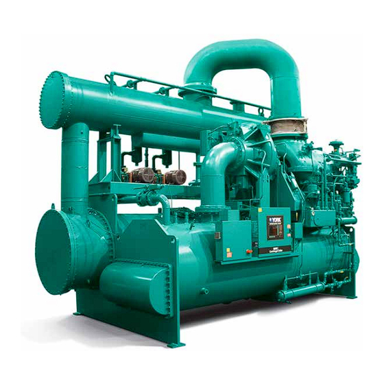
Page 7: Figure 1 - Model Yst Chiller
#2 (Optional) Hotwell Condensate Pump #1 Hotwell Condensate Level Indicator / Transmitter Vacuum Pump #2 (Optional) Vacuum Pump #1 Vacuum Pump #1 Sealing Water Solenoid Valve Vacuum Pump #1 Sealing Water Flow Switch FIGURE 1 - MODEL YST CHILLER JOHNSON CONTROLS... - Page 8 FORM 160.67-N1 ISSUE DATE: 8/29/2014 THIS PAGE INTENTIONALLY LEFT BLANK. JOHNSON CONTROLS...
-
Page 9: Section 1 - Introduction
3. When units are shipped dismantled, notify the nearest Johnson Controls of- Chillers can also be shipped dismantled when required fice in ample time for a Johnson Controls by rigging conditions, but generally it is more econom- representative to supervise rigging the unit... -
Page 10: Shipment
Partial pre-fabricated steam exhaust piping and neoprene isolation pads are JOHNSON CONTROLS WILL NOT BE RESPON- shipped loose. SIBLE FOR ANY DAMAGE IN SHIPMENT OR AT JOB SITE OR LOSS OF PARTS. (Refer to Shipping Damage Claims, Form 50.15-NM) -
Page 11: Chiller Data Plate
Figure 2 on page 12. condenser with prepiped accessories for the conden- sate and vacuum systems. The atmospheric relief valve is shipped loose for field assembly. JOHNSON CONTROLS... -
Page 12: Steam Condenser Package Rigging
If necessary, the condenser and accessory items may JOHNSON CONTROLS WILL NOT BE RESPON- be separated from the skid base. Disconnect bolting, SIBLE FOR ANY DAMAGE IN SHIPMENT OR AT piping and wiring as required. -
Page 13: Figure 3 - Steam Condenser Package Rigging
FORM 160.67-N1 SECTION 1 - INTRODUCTION ISSUE DATE: 8/29/2014 FIGURE 3 - STEAM CONDENSER PACKAGE RIGGING JOHNSON CONTROLS... -
Page 14: Figure 4 - Neoprene Isolators (Standard Dimensions)
UNIT WEIGHT 28,836 TO 53,530 LBS. UNIT WEIGHT 53,531 TO 100,464 LBS. LD09015 UNIT WEIGHT 100,465 TO 130,000 LBS. See York standard arrangement drawings for floor layout of Neoprene Isolators by model. FIGURE 4 - NEOPRENE ISOLATORS (STANDARD DIMENSIONS) JOHNSON CONTROLS... -
Page 15: Figure 5 - Neoprene Isolators (Metric Dimensions)
UNIT WEIGHT UP TO 7423 Kgs. UNIT WEIGHT 7424 TO 13,080 Kgs. LD09017 UNIT WEIGHT 45,667 TO 58,967 LBS. See York standard arrangement drawings for floor layout of Neoprene Isolators by model. FIGURE 5 - NEOPRENE ISOLATORS (METRIC DIMENSIONS) JOHNSON CONTROLS... - Page 16 FORM 160.67-N1 SECTION 1 - INTRODUCTION ISSUE DATE: 8/29/2014 THIS PAGE INTENTIONALLY LEFT BLANK. JOHNSON CONTROLS...
-
Page 17: Section 2 - Installation
At this point units shipped dismantled in place, care should be taken in leveling the condenser should be assembled under the supervi- package, shimming at the skid/tubesheet, if necessary. sion of a Johnson Controls representative. PIPING CONNECTIONS Water/Drains The chiller package and Steam Con- • Refrigerant condenser inlet/outlet**... -
Page 18: Steam/Vents
• Steam inlet strainer: Full flow strainer with fine must be corrected by properly supporting the piping or [3/64" (1.2 mm) perforations], stainless steel by applying heat to anneal the pipe. mesh, suitable for steam service. JOHNSON CONTROLS... -
Page 19: Water Piping
ECWT allowed. must be kept out of the water circuit. All water piping must be cleaned or flushed before being connected to the chiller, or other equipment. JOHNSON CONTROLS... -
Page 20: Stop Valves
Connection of the refrigerant charge to the atmosphere as a safety (Tee Supplied precaution in case of an emergency, such as fire. Inlet Pressure by Others) Gauge Connection LD09581 FIGURE 6 - OPTIONAL TURBINE GAUGEBOARD CONNECTIONS JOHNSON CONTROLS... -
Page 21: Steam Turbine Casing Drain Options
Strain on Relief Piping Flexible Connector Condensation Trap Refrigerant Condenser Relief Valves (See Note) Evaporator NOTE: Shells may be furnished with one or two relief valves, depending on shell size. LD09387 FIGURE 7 - TYPICAL REFRIGERANT VENT PIPING JOHNSON CONTROLS... - Page 22 AND OTHER INTERNAL PARTS. and overpressurization limits. JOHNSON CONTROLS ACCEPTS NO RESPONSI- Steam inlet and exhaust piping (if not supplied by BILITY FOR DAMAGE RESULTING FROM THE YORK) must be properly designed and supported so...
-
Page 23: Gland Seal Leak-Off Piping
The condensate from this gland condenser can be re- turned to the feed water system. The piping contractor is responsible for the form and fit of turbine steam piping. The piping must be installed with the flanges and bolt holes properly aligned. The JOHNSON CONTROLS... -
Page 24: Gland Leak-Off Condenser - Optional Supply By Special Quotation
On standard YST chillers with up-discharge turbine ex- higher pressures. haust, an exhaust casing drain connection is supplied. The turbine must be supplied with a means of drain- JOHNSON CONTROLS... -
Page 25: Condensate Drain Tank - Optional Supply By Special Quotations
DO NOT make final power connections to power pan- drained by closing and opening the appropriate valves el until approved by Johnson Controls representative. to isolate the tank from the turbine during the drain- When the steam condenser package is... -
Page 26: Floor Mounted Steam Condenser
Notification These interconnecting components must be designed, to the Johnson Controls office should be by means of supplied and installed by others. completing the Installation Check List and Request External piping loads to the steam inlet Forms in the back of the 160.67-O2 manual. -
Page 27: Figure 8 - Typical Manual Start Piping Arrangement
FORM 160.67-N1 SECTION 2 - INSTALLATION ISSUE DATE: 8/29/2014 MANUAL START FIGURE 8 - TYPICAL MANUAL START PIPING ARRANGEMENT JOHNSON CONTROLS... - Page 28 FORM 160.67-N1 SECTION 2 - INSTALLATION ISSUE DATE: 8/29/2014 MANUAL START FIGURE 8 – TYPICAL MANUAL START PIPING ARRANGEMENT (CONT'D) JOHNSON CONTROLS...
-
Page 29: Alignment
• Check the grouting to assure it is complete and supports the structure of the unit. • Check all foundation bolts to assure tightness. JOHNSON CONTROLS... -
Page 30: Figure 9 - Typical Arrangement For "Face - O.d." Readings To Determine Cold Alignment Of Shafts
Refer to the following , "Checking for Sag" sec- tion in this manual. Especially when the spans between the shafts are quite long, care must be taken to assure that the bracket being utilized is stiff enough that it will not deflect under its own weight. JOHNSON CONTROLS... -
Page 31: Checking For Sag
SAG or Figure 11 on page 31. by determining the deflection in the alignment fixture and making the appropriate corrections in the align- ment data. (See the checking for Sag section previ- ously discussed in this manual) JOHNSON CONTROLS... - Page 32 Alignment" check of the driveline alignment at operat- to temperature, stop it, break couplings, and attempt ing temperatures is required. to determine alignment before it cools off, but the re- JOHNSON CONTROLS...
-
Page 33: Temperature
(°C), subtract 32° and multiply by 5/9 or 0.5556. Example: (45.0°F - 32°) x 0.5556 = 27.2°C To convert a temperature range (i.e., a range of 10°F) from Fahrenheit to Celsius, multiply by 5/9 or 0.5556. Example: 10.0°F range x 0.5556 = 5.6 °C range JOHNSON CONTROLS... - Page 34 P.O. Box 1592, York, Pennsylvania USA 17405-1592 800-861-1001 Subject to change without notice. Printed in USA Copyright © by Johnson Controls 2014 www.johnsoncontrols.com ALL RIGHTS RESERVED Form 160.67-N1 (814) Issue Date: August 29, 2014 Supersedes: 160.67-N1 (504)
Need help?
Do you have a question about the YORK YST and is the answer not in the manual?
Questions and answers