Advertisement
Quick Links
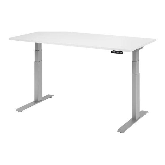
Tone Electric and Extended Electric
Note that these instruc ons show generic parts. Parts included in individual tables may differ in appearance and func onality
but the assembly principle is the same.
Cau on: No impact drivers or other high‐torque equipment are to be used
Complete product without work surface
Housing
Sidebar
Column
Complete product with work surface
ASSEMBLY INSTRUCTIONS
Crossbar
Foot
90⁰
120⁰
90⁰
120⁰
1
07.17
!
Advertisement

Related Manuals for Knoll Tone Electric


Summary of Contents for Knoll Tone Electric
- Page 1 ASSEMBLY INSTRUCTIONS 07.17 Tone Electric and Extended Electric Note that these instruc ons show generic parts. Parts included in individual tables may differ in appearance and func onality but the assembly principle is the same. Cau on: No impact drivers or other high‐torque equipment are to be used Complete product without work surface ...
- Page 2 ASSEMBLY INSTRUCTIONS 07.17 (Fig. 1) Feet Alterna ve foot types. KR68003496 On‐Foot / OnC (for 2‐stage columns) Screw Socket Round UNC 5/16‐18x5/8” Zn Maximum Torque from 3 to 5 lbf· . On‐Foot / OffC (for 2‐stage columns) In‐Foot / OnC (for 3‐stage columns) In‐Foot / OffC (for 3‐stage columns) (Fig. 2) Crossbars Do not use the two middle holes of the crossbars. Adjustable crossbar Loosen Screws to adjust crossbar length ...
- Page 3 ASSEMBLY INSTRUCTIONS 07.17 (Fig. 3) Sidebars Symmetric Sidebar for T‐leg Part number: KR3ae4015 KR79100036 Screw Philips Undercut Flat Head 1/4 ‐20x5/8” Zn Right Hand / Le Hand sidebars for C‐leg Part numbers: KR3ae4014L ‐ Le KR3ae4014R ‐ Right (Fig. 4) Bumpers KR68003468 KR68003467 Bumper 1/2"x1/2"x1/4" Transparent Bumper Ø1/2"x1/8" Transparent Place thin bumpers on tube next to Screw hole and ...
- Page 4 ASSEMBLY INSTRUCTIONS 07.17 (Fig. 5) 3‐Column 90⁰ Adjustable Crossbars Adjustable crossbars for 3‐column 90⁰ table. 3 regular adjustable crossbars Special 1 special adjustable crossbar telescopic crossbar Alterna ve foot KR68003491 Screw Socket CSK No addi onal assembly kit UNC 5/16‐18x1‐1/2" Zn (Fig. 6) 3‐Column 90⁰ Fixed Crossbars Fixed crossbars for 3‐column 90⁰ table. Regular fixed crossbar ...
- Page 5 ASSEMBLY INSTRUCTIONS 07.17 (Fig. 7) 3‐Column 120⁰ Adjustable Crossbars Adjustable crossbars for 3‐column 120⁰ table. 4 regular adjustable crossbars KR68005205 Hex Nut UNC 5/16‐18 Zn 2 Brackets KR3AE4121 Bracket Outer KR3AE4120 Bracket Inner KR68003490 Screw Socket CSK UNC 5/16‐18x1" Zn (Fig. 8) 3‐Column 120⁰ Fixed Crossbars KR68005205 Fixed crossbars for 3‐column 120⁰ table. Hex Nut UNC 5/16‐18 Zn ...
- Page 6 ASSEMBLY INSTRUCTIONS 07.17 (Fig. 9) Electrical 2‐Column KR3ae4025 ‐ ASM Light Handset KR68003761 Power Supply D04 35V/2,12A AC input 100‐240V, 50‐60Hz KR68002262 Cable USA 2‐pol IEC C7 DIN 57625 KR3ae4026 ‐ Handset w Display KR68002414 / KR68003122 KR68002583 / KR68002489 Cable LinBus iDrive 800 / 1200 / 1600 / 2000 KR3ae4025 ASM Light Handset w Screws *Use P‐Clip KR79100378 (Fig.10) Electrical 3‐Column 90⁰ KR3ae4051 Holder for Power Supply KR68003761 Power Supply D04 35V/2,12A AC input 100‐240V, 50‐60Hz Hooks over crossbar or screws into work KR68002262 surface. Cable USA 2‐pol IEC C7 DIN 57625 KR68002414 / KR68003122 KR68002583 / KR68002489 *KR79100378/KR79100379 ...
- Page 7 ASSEMBLY INSTRUCTIONS 07.17 (Fig. 11) Electrical 3‐Column 120⁰ KR68003761 Power Supply D04 35V/2,12A AC input 100‐240V, 50‐60Hz KR68002262 Cable USA 2‐pol IEC C7 DIN 57625 KR79100380 P‐clips must be installed to secure any cables hanging down more than 1.5 inches from the bo om of the work surface KR68002414 / KR68003122 KR68002583 / KR68002489 Cable LinBus iDrive 800 / 1200 / 1600 / 2000 KR3ae4025 ASM Light Handset w Screws Warning Leaflet Tone Electric User Manual Tone Electric Warning leaflet and user manual should be le on the table a er completed installa on. 7 ...
-
Page 8: Assembly Procedure
ASSEMBLY INSTRUCTIONS 07.17 ASSEMBLY PROCEDURE Fig. 1 FEET Assemble the feet on the columns. Tighten screws firmly. Maximum Torque from 3 to 5 lbf· . IMPORTANT: Make sure the correct screws are used. Using too long screws may destroy internal parts in the column. Fig. 2 CROSSBARS A ach the crossbars on the long side of the houses. Tighten screws firmly. IMPORTANT: Do not use the two middle holes of the crossbars. - Page 9 ASSEMBLY INSTRUCTIONS 07.17 Fig. 7‐8 3‐COLUMN 120⁰ TABLE 4 regular adjustable or fixed crossbars are used together with two 120⁰ brackets that a ach to the middle column. The assembly procedure is the same as for a 2‐column table. The 120⁰ brackets are a ached with bolts and nuts. Fig. 9 ‐11 ELECTRONICS The handset is mounted at the front edge of the work surface, screwed to the underside with screws supplied with the unit. Connect cables and power supply according to fig. 9 ‐ 11 9 ...
- Page 10 ASSEMBLY INSTRUCTIONS 07.17 Troubleshoo ng guide for Tone Electric and Extended Electric Some of the proposed ac ons in this guide should only be performed by a service technician. End users should not a empt replacing parts. WARNING: Do NOT sit on base while assembling in progress. Homing WARNING: Do NOT sit on the table to apply body weight for performing the homing process. If a table has been reconfigured, or a component (i.e. cable, motor or electronic) has been recon‐ nected or replaced during or a er the assembly, a homing cycle must be performed. A homing cycle (some mes referred to as a table reset) should be performed with an even weight(!) of approx. 100lbs. applied on the table. Ini ate a new homing cycle by: 1. Simultaneously pressing the up and down bu ons for a minimum of 8 seconds. ...
- Page 11 ASSEMBLY INSTRUCTIONS 07.17 3. Table moving in one direc on only 3.1. Only running down in slow speed: ‐ The table is in homing mode. To allow the table to complete the homing cycle, drive all the way down to lowest posi on to complete the homing cycle. 3.2. Only able to drive up or only down, but in normal speed: ‐ Ini ate a new homing cycle by holding the up and down bu ons on the hand control pressed for 8 seconds. Drive the table all the way down to lowest posi on to complete the homing cycle. 3.2.1. S ll no func on: ‐ Replace hand control. 3.2.2. S ll no func on: ‐ Replace the column. 4. Table only running a short while and then stopping 4.1. ...
- Page 12 New document AB Rev B 2014‐04‐27 Page 2 ‐ 1/4” screw changed to 5/16” AB Rev C 2014‐05‐07 Changes made according to Knoll request +Homing added AB/PERLOH Rev D 2014‐09‐26 Changes made by adding trouble guide. TONSVE Rev E 2014‐10‐01 New name procuct and black and white text, minor changes PERLOH Rev F 2015‐03‐03 Fig. 3, 79100036 was 68003465 JONLAR Rev G 2016‐04‐26 Wood screws Fig.4 changed ...
Need help?
Do you have a question about the Tone Electric and is the answer not in the manual?
Questions and answers