Table of Contents
Advertisement
Quick Links
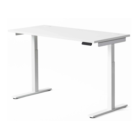
k.stand Electric and Extended Electric
Note that these instructions show generic parts. Parts included in individual tables may differ in appearance and functionality but the
assembly principle is the same.
Caution:
Complete product
Motor Housing
Complete product with worksurface
ASSEMBLY INSTRUCTIONS
Adjustable-Width
Crossbar
Side Bracket
Column
Foot
90°
120°
90°
120°
1
08.18
Advertisement
Table of Contents

Related Manuals for Knoll k.stand Electric


Summary of Contents for Knoll k.stand Electric
- Page 1 ASSEMBLY INSTRUCTIONS 08.18 k.stand Electric and Extended Electric Note that these instructions show generic parts. Parts included in individual tables may differ in appearance and functionality but the assembly principle is the same. Caution: Complete product 90° Motor Housing Adjustable-Width 120°...
- Page 2 ASSEMBLY INSTRUCTIONS 08.18 (Fig. 1) Crossbars 2 Adjustable Crossbars [Min 40.4” to Max 58.75”] (8) Screw Socket Flat Head M8 x 16 ZN (Fig. 2) Side Brackets T-Leg and C-Leg Side Brackets (4) 1/4-20x5/8 Undercut Flathead, 100 degree...
- Page 3 ASSEMBLY INSTRUCTIONS 08.18 Alternative Foot Types (Fig. 3) Feet T-Leg Foot (4) Screw Socket Round M8 x 16 ZN C-Leg Foot Casters (shown on foot) Locking Caster (1) Non-locking Caster (not shown) Hex Nut 5/16-18x1/2 (2) Loosen set screws to adjust crossbar length (Fig.
- Page 4 ASSEMBLY INSTRUCTIONS 08.18 Bracket Worksurface Screws (Fig. 5) Side Bracket to Worksurface (4) #10 x 1” wood screws Crossbar Worksurface Screws (Fig. 6) Crossbar to Worksurface (4 min/10 max) #10 x 2 1/2” wood screw #10 x 2 1/2” wood screw Install thru all available crossbar (4 min/10 max) to worksurface holes.
- Page 5 ASSEMBLY INSTRUCTIONS 08.18 3 Adjustable Crossbars (Fig. 7) 3-Column 90° (2) Screw Socket Flat M8 x 16 ZN (12) Round Bumper 1/2”x1/2”x1/4” (3) Square Bumper Transparent [Min 40.4” to Max 58.75”] 1/2”x1/2”x1/4” Transparent 1 40x20 Fixed Crossbar 3rd Leg Foot Once crossbars are set, place (1) round rubber bumper midway 40x20 Fixed Crossbar...
- Page 6 ASSEMBLY INSTRUCTIONS 08.18 3 Adjustable Crossbars (Fig. 9) 120° Assembly Close-up (8) Screw Socket Flat Head M8 x 16 ZN [Min 40.4” to Max 58.75”] 120° Bracket 1 40x20 Fixed Crossbar 3rd Leg Foot Attach 120° bracket to motor house before attaching crossbar (Fig.
- Page 7 ASSEMBLY INSTRUCTIONS 08.18 120° Bracket (Fig. 11) 120° Worksurface Screws (3) #14 x2 1/2 wood screws (3) #10 x 1” wood screws (Fig. 12) 90° & 120° Worksurface Screws (3 min/12 max) #10 x 2 1/2” wood screw Install thru all available crossbar to worksurface holes. All Minimized crossbars = 3 screws All Maximized crossbars = 12 screws...
- Page 8 ASSEMBLY INSTRUCTIONS 08.18 Standard Handset (Fig. 13) Electrical 2-Column Power Supply Output 35V Input 110V US Power Cord Digital Handset ECS + Control Box 470 AC ON ECS + Control Box 650 AC ON Digital Handset with Screws Toggle Handset (Fig.
- Page 9 ASSEMBLY INSTRUCTIONS 08.18 (Fig. 15) Electrical 3-Column 120° US Power Cord Power Supply Output 35V Input 110V ECS + Control Box 470 AC ON ECS + Control Box 650 AC ON Digital Handset with Screws Warning Leaflet Electric k.stand User Manual Warning leaflet and user manual to be left on the table after completed installation.
- Page 10 ASSEMBLY INSTRUCTIONS 08.18 ASSEMBLY PROCEDURE Fig. CROSSBARS WORKSURFACE ATTACHMENT Fig. 1 Attach the crossbars on the long side of the 5-6,12 Two sizes of wood screw for the worksurface are included in the 2-leg assembly kit, and an motor houses. additional size in the 3rd leg assembly kit.
Need help?
Do you have a question about the k.stand Electric and is the answer not in the manual?
Questions and answers