Table of Contents
Advertisement
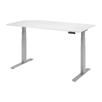
Wall Mount Height Adjustable Table
Reference Number: 6TP00587
Table of Contents
Prepare Mid Gable if Table is 72" or Wider
Skip Steps 18 & 19 (sheet 9) if Table is Under 72" Wide
Reff Profiles
™
December 20, 2019
Reff Profiles
™
Installation Instruction
1-9
10
11-12
13-16
17
18
19
20-21
22-23
24
25
25
26
27
28-30
Part Number: 6TP00587
Sheet a
Advertisement
Table of Contents

Related Manuals for Knoll Reff Profiles 6TP00587


Summary of Contents for Knoll Reff Profiles 6TP00587
-
Page 1: Table Of Contents
Reff Profiles ™ Installation Instruction Wall Mount Height Adjustable Table Reference Number: 6TP00587 Table of Contents Safety First & Assembly & Adjustment Pattern Numbers Represented / Tools Needed / Part List Construct Base Assembly 11-12 Assemble Notched Top and Attach Bracketry 13-16 Prepare and Attach Gables Prepare Mid Gable if Table is 72”... -
Page 2: Safety First & Assembly & Adjustment
The information and specifications included in this manual were in effect at the time of approval for printing. Knoll reserves the right to discontinue or change specifications or design at anytime without notice and without incurring any obligation whatsoever. - Page 3 Reff Profiles ™ Installation Instruction Wall Mount Height Adjustable Table Reference Number: 6TP00587 1.1 Important Safety Instructions Please save these instructions. Read instructions thoroughly before using table. When using an electrical table, basic precautions should always be followed, including the following: DANGER To reduce the risk of electric shock: 1.
- Page 4 Reff Profiles ™ Installation Instruction Wall Mount Height Adjustable Table Reference Number: 6TP00587 DANGER Risk of electric shock, injury, or death: 1. Improper usage, abuse, or misuse of the power supply, handset, motors and other electrical components may result in an electrical shock injury or possible death.
- Page 5 Reff Profiles ™ Installation Instruction Wall Mount Height Adjustable Table Reference Number: 6TP00587 7. The table must only be operated while in an upright position and must under no circumstances be operated while upside down. 8. The table must not be overloaded. The maximum allowable load is shown on the power supply label.
- Page 6 2019-11-13 Input: 120VAC 3.2A 60Hz Output: DC35V Duty Cycle: 1min on/ 9min off This Knoll REFF® motorized table desk Conforms to ULSTD962 ED.4 5000828 5000828 Certified to CAN/CSA STDC22.2 No. 68 2009 CAUTION - Risk of Electric Shock Make sure to unplug all power supply cords before moving or servicing this furnishing.
- Page 7 Reff Profiles ™ Installation Instruction Wall Mount Height Adjustable Table Reference Number: 6TP00587 Assembly & Adjustment 2.1 Assembly Instructions The official assembly instructions can be found with the base components. Make sure to ask your desk vendor for an approved combination of desktop and frame. Reff Profiles ™...
- Page 8 Reff Profiles ™ Installation Instruction Wall Mount Height Adjustable Table Reference Number: 6TP00587 2.2 Setup Procedure CAUTION Risk of electrical shock: The main power cord must be unplugged during the setup. To setup the table: 1. Connect the handset to a 3-pin motor/motor house or to Bus cable socket. P/N: KR3AF4102, KR3AF4103 2.
- Page 9 Reff Profiles ™ Installation Instruction Wall Mount Height Adjustable Table Reference Number: 6TP00587 2.3 Optional Mounting Guidelines NOTICE When disconnecting components such as the power supply, Bus cable or the handset, the strain relieve hook must be pressed before removing the connector. When inserting the connector, an audible “click”...
- Page 10 Reff Profiles ™ Installation Instruction Wall Mount Height Adjustable Table Reference Number: 6TP00587 2.4 System Configuration (Example) The figure below shows a configuration example consisting of: 1. Power Supply 2. Bus cable Handset 2.5 Adjustment The table control, handset and motors are sealed units and have no parts that can be serviced or adjusted by the user. In case of failure/unexpected operation or for maintenance please contact your vendor or arrange for service by a qualified technician.
-
Page 11: Pattern Numbers Represented / Tools Needed / Part List
Reff Profiles ™ Installation Instruction Wall Mount Height Adjustable Table Reference Number: 6TP00587 Pattern Numbers represented: Wall Mounted Height Adjustable Table, RWM_ _ _ Tools Needed: Wrench for hex bolt at glide Hex bits: Various Torque Wrench with 8mm Hex Bit Socket (for 57ft-lbs) Power Driver with #2, #3 &... -
Page 12: Construct Base Assembly
Reff Profiles ™ Installation Instruction Wall Mount Height Adjustable Table Reference Number: 6TP00587 Part List: (A) Leg Column (2 stage) (B) Adjustable Width Crossbar (C) 5/16-18x1” Socket Screw (D) Width Adjustment Set Screw (A) 6TP42005 (B) 3AE401701, 3AE401801, 3AE401901 (S, M, L) only M shown STEPS: (C) 68003490 (within 3AE4032 kit) - Page 13 Reff Profiles ™ Installation Instruction Wall Mount Height Adjustable Table Reference Number: 6TP00587 Part List: (E) Cantilever Bracket, RH (F) Cantilever Bracket, LH (G) ¼-20 x 5/8” Phillips Undercut Flat Head Screw (E) 6TP41967R (F) 6TP41967L (G) 79100036 (within 3AE4032 kit) 6tp00587_190725_hardware_2.ai Fig.
- Page 14 Reff Profiles ™ Installation Instruction Wall Mount Height Adjustable Table Reference Number: 6TP00587 Part List: (A) Leg Column (2 stage) (H) Leg Grommet Sleeve ( I ) Notched Top (J) Leg Support Bracket (K) 5/16-18 x 1” Round Head Socket Screw (L) 5/16- 18 Hex Standoff (A) 6TP42005 (H) 6TP41310...
- Page 15 Reff Profiles ™ Installation Instruction Wall Mount Height Adjustable Table Reference Number: 6TP00587 Part List: (N) Leg Bottom Bracket (O) ¼-20 x 5/8 Hex Head Bolt (P) ¼ -20 Hex Nut (N) 6TP42138 (O) 6TR4042 (P) 7061140 6tp00587_190725_hardware_4.ai Fig. 4 Leg bottom brackets Assemble Notched Top and Attach Bracketry (cont.)
-
Page 16: Assemble Notched Top And Attach Bracketry
Reff Profiles ™ Installation Instruction Wall Mount Height Adjustable Table Reference Number: 6TP00587 Part List: (D) Width Adjustment Set Screw ( I ) Notched Top (Q) Leg Top Bracket (R) #14 x 7/8” Pan Head Wood Screw (D) 3AE4050 ( I ) Notched Top (varies per width) (Q) 6TP42170 (R) 5122218 Fig. - Page 17 Reff Profiles ™ Installation Instruction Wall Mount Height Adjustable Table Reference Number: 6TP00587 Part List: (Q) Leg Top Bracket (P) ¼ -20 Hex Nut (S) Rear Brace (T) Square Rubber Bumper (U) Round Rubber Bumper (Q) 6TP42170 (P) 7061140 (S) Rear Brace (T) 68003468 (U) 68003467 (varies per width)
-
Page 18: Prepare And Attach Gables
Reff Profiles ™ Installation Instruction Wall Mount Height Adjustable Table Reference Number: 6TP00587 Part List: 1x1x3 L-bracket (W) Right Hand End Gable Left Hand End Gable #10 x ¾” Pan Head Wood Screw Disc Plate (AA) 7x50mm Confirmat Screw (BB) Multi-Clip (V) 5340110 (W) 6TP13320 (X) 6TP13321... - Page 19 Reff Profiles ™ Installation Instruction Wall Mount Height Adjustable Table Reference Number: 6TP00587 Part List: 1x1x3 L-bracket #10 x ¾” Pan Head Wood Screw (BB) Multi-Clip (CC) #8 x 1” Flat Head Wood Screw (EE) Mid Gable (V) 5340110 (Y) 5112220 (BB) 6TR41189 (CC) 5114120 (EE) 6TP13324...
-
Page 20: Attach End Gable
Reff Profiles ™ Installation Instruction Wall Mount Height Adjustable Table Reference Number: 6TP00587 Fig. 9 Attach end gables Part List: ( I ) Notched Top (S) Rear Brace (Y) #10 x ¾” Pan Head Wood Screw (Z) Disc Plate Front edge ( I ) Notched Top (varies per width) Right end gable shown installed... -
Page 21: Wall Mounting Suggestions
It is the responsibility of the Customer and its structural engineers/architects to verify that the permanent structural walls (studs, blocks, solid masonry, etc.) on which the Knoll products are intended to be mounted are designed appropriately to support the product weight, PLUS 3 lbs. per linear inch for each usable shelf length. - Page 22 Fasten the Knoll Replace the drywall Replace the drywall Replace the drywall Replace the drywall and repair as desired. Supplied Rear Brace and repair as desired.
-
Page 23: Position And Secure Basea
(N, V, & S) to the end gables, as necessary, to achieve a level Knoll does not assume any responsibility for wall using appropriate customer-supplied top surface and level crossbars. Ideally, the the installation, attachment, or securing of fasteners in all previously marked locations. - Page 24 Reff Profiles ™ Installation Instruction Wall Mount Height Adjustable Table Reference Number: 6TP00587 Part List: ¼ -20 Hex Nut Leg Top Bracket (FF) Leg Top Inside Bracket (GG) #10 x 7/8 Tek Screw (HH) 1/4-20 x 3” UNC Button Head Cap Screw (P) 7061140 (Q) 6TP42170 (FF) 6TP42137...
-
Page 25: Electrify Base
Reff Profiles ™ Installation Instruction Wall Mount Height Adjustable Table Reference Number: 6TP00587 Part List: ( I I ) Power Supply (JJ) iDrive Cables, 31”, 63”, 78” ( I I ) 3AE4031 (JJ) 3AE4027, 3AE4029, 3AE4030 (KK) 3AE4051 (KK) Power Supply Bracket (31”, 63”, 78”) only 31”... -
Page 26: Install Worksurface Top
Reff Profiles ™ Installation Instruction Wall Mount Height Adjustable Table Reference Number: 6TP00587 Part List: Adjustable Width Crossbar Cantilever Bracket, RH Cantilever Bracket, LH (LL) Handset Kit, Standard, consisting of: Standard Handset (MM) #8 x 3/4" Pan Head Zinc Wood Screw (B) 3AE401701, 3AE401801, 3AE401901 (E) 6TP41967R (F) 6TP41967L... -
Page 27: Prepare The Frontset For Attachment
Reff Profiles ™ Installation Instruction Wall Mount Height Adjustable Table Reference Number: 6TP00587 Part List: (BB) Multi-Clip (CC) #8 x 1” Flat Head Wood Screw (UU) Hinged Frontset (BB) 6TR41189 (CC) 5114120 (UU) Hinged Frontset (varies per width) 6tp00587_190725_hardware_14.ai Prepare the Frontset for Attachment Fig. -
Page 28: Position Mid Gable If Table Is 72" Or Wider. Skip Step 34 If Table Is Under 72" Wide
Reff Profiles ™ Installation Instruction Wall Mount Height Adjustable Table Reference Number: 6TP00587 Part List: ( I ) Notched Top Rear Brace 1x1x3 L-bracket (S) Rear Brace (varies per width) ( I ) Notched Top (varies per width) #10 x ¾” Pan Head Wood Screw (BB) Multi-Clip (EE) Mid Gable (V) 5340110... -
Page 29: Attach Frontset
Reff Profiles ™ Installation Instruction Wall Mount Height Adjustable Table Reference Number: 6TP00587 Part List: ( I ) Notched Top #10 x ¾” Pan Head Wood Screw Right Hand End Gable Left Hand End Gable ( I ) Notched Top (varies per width) (Y) 5112220 (W) 6TP13320 (X) 6TP13321... - Page 30 Reff Profiles ™ Installation Instruction Wall Mount Height Adjustable Table Reference Number: 6TP00587 Part List: ( I ) Notched Top Right Hand End Gable (BB) Multi-Clip (UU) Hinged Frontset (XX) Grommet Inner Sleeve (YY) Grommet Front Ring (ZZ) #8 x 3/8” Flat Head Screw ( I ) Notched Top (varies per width) (W) 6TP13320 (BB) 6TR41189...
- Page 31 Reff Profiles ™ Installation Instruction Wall Mount Height Adjustable Table Reference Number: 6TP00587 Part List: (UU) Hinged Frontset (XX) Grommet Inner Sleeve (YY) Grommet Front Ring (ZZ) #8 x 3/8” Flat Head Screw (EEE) Grommet Back Plate (UU) Hinged Frontset (varies per width) (XX) 6TP40363 (YY) 6TP40362 (ZZ) 6TP42196 (EEE) 6TP40361...
Need help?
Do you have a question about the Reff Profiles 6TP00587 and is the answer not in the manual?
Questions and answers