Advertisement
Quick Links
Tone Fixed Height
Note that these instruc ons show generic parts. Parts included with individual tables may differ in appearance and func onality,
but the assembly principle is the same.
Cau on: No impact drivers or other high‐torque equipment are to be used
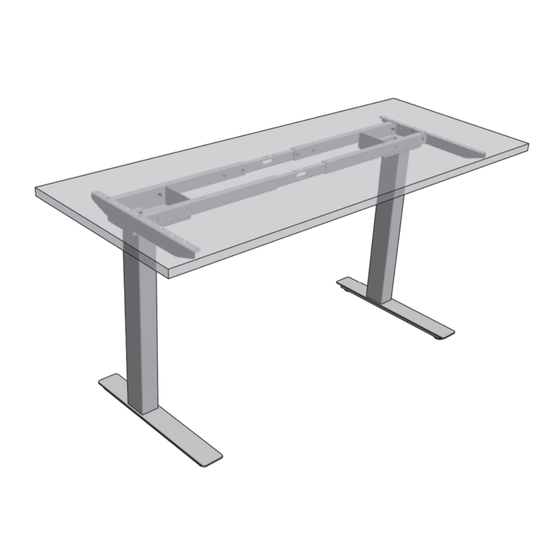
Complete product without work surface
Housing
Sidebar
Column
Foot
Complete product with work surface
ASSEMBLY INSTRUCTIONS
Crossbar
120⁰
90⁰
1
90⁰
120⁰
07.17
!
Advertisement

Related Manuals for Knoll Tone Fixed Height


Summary of Contents for Knoll Tone Fixed Height
- Page 1 ASSEMBLY INSTRUCTIONS 07.17 Tone Fixed Height Note that these instruc ons show generic parts. Parts included with individual tables may differ in appearance and func onality, but the assembly principle is the same. Cau on: No impact drivers or other high‐torque equipment are to be used Complete product without work surface 90⁰ Housing Crossbar Sidebar Column 120⁰ Foot Complete product with work surface 90⁰ 120⁰ 1 ...
- Page 2 ASSEMBLY INSTRUCTIONS 07.17 (Fig. 1) Feet Alterna ve Foot Types KR68003496 Screw Socket Round UNC 5/16‐18x5/8” Zn On‐Foot / OnC Maximum Torque from 3 to 5 lbf· On‐Foot / OffC In‐Foot / OnC In‐Foot / OffC Carefully measure out desired work surface height before adjus ng columns. Height can only be adjusted on an unloaded column. (Fig. 2) Crossbars Crossbar Types Adjustable width Fixed width Do not use the two middle Loosen screws to adjust crossbar ...
- Page 3 ASSEMBLY INSTRUCTIONS 07.17 (Fig. 3) Sidebars Sidebar Types KR79100036 Screw Philips Undercut Flat Head 1/4 ‐20x5/8” Zn Right Hand / Le Hand sidebars for C‐leg Part numbers: KR3ae4014L ‐ Le KR3ae4014R ‐ Right Symmetric Sidebar for T‐leg Part number: KR3ae4015 (Fig. 4) Bumpers KR68003468 Bumper KR68003467 Bumper Ø1/2”x1/8” Transparent Place thick bumpers on C‐channel next to screw hole Place thin bumpers on tube next to screw hole and next to tube edge 3 ...
- Page 4 ASSEMBLY INSTRUCTIONS 07.17 (Fig. 5 ) 3‐Column 90⁰ Adjustable Crossbars Adjustable crossbars for 3‐column 90⁰ table. 3 regular adjustable crossbars 1 special adjustable crossbar Special adjustable crossbar Alterna ve foot No addi onal assembly kit KR68003491 Screw Socket CSK 5/16‐18x1‐3/8”Zn (Fig. 6) 3‐Column 90⁰ Fixed Crossbars Regular fixed crossbar Regular fixed crossbar Regular fixed crossbar 6” Fixed crossbars for 3‐column 90⁰ table. shorter than the other three crossbars 3 regular fixed crossbars Alterna ve foot KR68003491 ...
- Page 5 ASSEMBLY INSTRUCTIONS 07.17 (Fig. 7 ) 3‐Column 120⁰ Adjustable Crossbars Adjustable crossbars for 3‐column 120⁰ table. 4 regular adjustable crossbars KR68005205 Nut Hex UNC 5/16‐18 Zn 2 Brackets KR3AE4121 Bracket Outer KR3AE4120 Bracket Inner KR68003490 Screw Socket CSK UNC 5/16‐18x1” Zn (Fig. 8) 3‐Column 120⁰ Fixed Crossbars Fixed crossbars for 3‐column 120⁰ table. 4 regular fixed crossbars KR68005205 Nut Hex UNC 5/16‐18 Zn 2 Brackets KR3AE4121 Bracket Outer KR3AE4120 Bracket Inner KR68003490 Screw Socket CSK UNC 5/16‐18x1” Zn ...
-
Page 6: Assembly Procedure
ASSEMBLY INSTRUCTIONS 07.17 ASSEMBLY PROCEDURE ENGLISH Fig. 1 FEET Assemble the feet on the columns. Tighten screws firmly. Maximum Torque from 3 to 5 lbf· . IMPORTANT: Make sure the correct screws are used. Fig. 2 CROSSBARS A ach the crossbars on the long side of the housings. Tighten screws firmly. IMPORTANT: Do not use the two middle holes of the crossbars. ... - Page 7 ASSEMBLY INSTRUCTIONS 07.17 ENGLISH Fig. 5 3‐COLUMN 90⁰ TABLE, ADJUSTABLE CROSSBARS 3 regular adjustable crossbars and 1 special adjustable crossbar with an angled C‐channel are used. Fig. 6 3‐COLUMN 90⁰ TABLE, FIXED CROSSBARS 3 regular fixed crossbars together with 1 regular fixed crossbar 6” shorter than the other three are used. The assembly procedure is the same as for a 2‐column table with the excep on that the angled C‐channel mounts to the center housing with one extra‐long screw 1‐3/8”. An alterna ve foot, shaped as a spacer, is used on the center column. Fig. 7‐8 3‐COLUMN 120⁰ TABLE 4 regular adjustable or fixed crossbars are used together with two 120⁰ brackets that a ach to the center column. The assembly procedure is the same as for a 2‐column table. The 120⁰ brackets are a ached to the crossbars with bolts and nuts.
- Page 8 2015‐03‐03 Fig. 3, 79100036 was 68003465 JONLAR Rev D 2016‐04‐12 Wood screws Fig.4 changed LINPHA Text modified a er Knoll input Revised wood screws in Fig. 4, Page 6 Revised screw types in Fig. 2, 5, 6, 7 & 8 ...
Need help?
Do you have a question about the Tone Fixed Height and is the answer not in the manual?
Questions and answers