Finn T90-II HydroSeeder Parts And Operator's Manual
Hide thumbs
Also See for T90-II HydroSeeder:
- Operator instructions and parts manual (126 pages) ,
- User manual and installation instructions (115 pages) ,
- Operator's manual (83 pages)
Table of Contents

Related Manuals for Finn T90-II HydroSeeder


Summary of Contents for Finn T90-II HydroSeeder
- Page 1 Activate Your Warranty By Registering TODAY!!! 9281 LeSaint Drive • Fairfield, Ohio 45014 Phone (513) 874-2818 • Fax (513) 874-2914 Sales: 1-800-543-7166 T90-II HydroSeeder ® Parts and Operator’s Manual Model SR Serial No. _____________ LBT90-SR Rev. A...
- Page 2 NOTES...
- Page 3 IF FINN CORPORATION DOES NOT HAVE YOUR COMPLETED REGISTRATION FORM ON FILE, YOUR WARRANTY CLAIM WILL BE DENIED. Once your Finn equipment has been registered, your Finn Limited Warranty will be activated per the warranty statement on the other side of this notice.
- Page 4 (except those referred to herein) that are manufac- dealers, or any other party. tured by Finn to be free from defects in material and workmanship 5. This Warranty does NOT cover any costs associated with trans- for a period of 12 months from date of purchase or 1200 hours of use, whichever comes first.
-
Page 5: Table Of Contents
Definition of Hydroseeding ........6 The Finn HydroSeeder® & How It Works ......6 Mounting The HydroSeeder®... - Page 6 INDEX Continued . . . Clump Maintenance ........24-25 Pump Maintenance .
-
Page 7: Safety First
SAFETY FIRST With any piece of equipment, new or used, the most important part of its operation is SAFETY! Finn Corporation encourages you and your employees to familiarize yourselves with your new equipment and to stress safe operation. The first six pages of this manual are a summary of all the main safety aspects associated with this unit. -
Page 8: Safety Summary Section
The FINN HydroSeeder® is designed to mix and apply water, seed, fertilizer, agricultural lime and hydraulic mulch to the prepared seedbed. The resultant slurry from mixing one or more of the above materials may react causing harmful or deadly gasses within the tank. - Page 9 6. Operator(s) equipment 3. Recirculation valve must be open and material flow- should never ride on the ing back into the tank when using the remote valve. A machine at speeds of greater closed or plugged recirculation line will cause extreme than 5 MPH (8 kmh).
- Page 10 29 CFR 1910.146. Including the following: 9. It is recommended that only authorized genuine FINN Drain, flush and ventilate tank interior. replacement parts be used on the machine. Turn off engine and disconnect battery cables and perform lockout/tagout procedures.
- Page 11 FIGURE 1 - Current Set of Safety Decals...
-
Page 12: Definition Of Hydroseeding
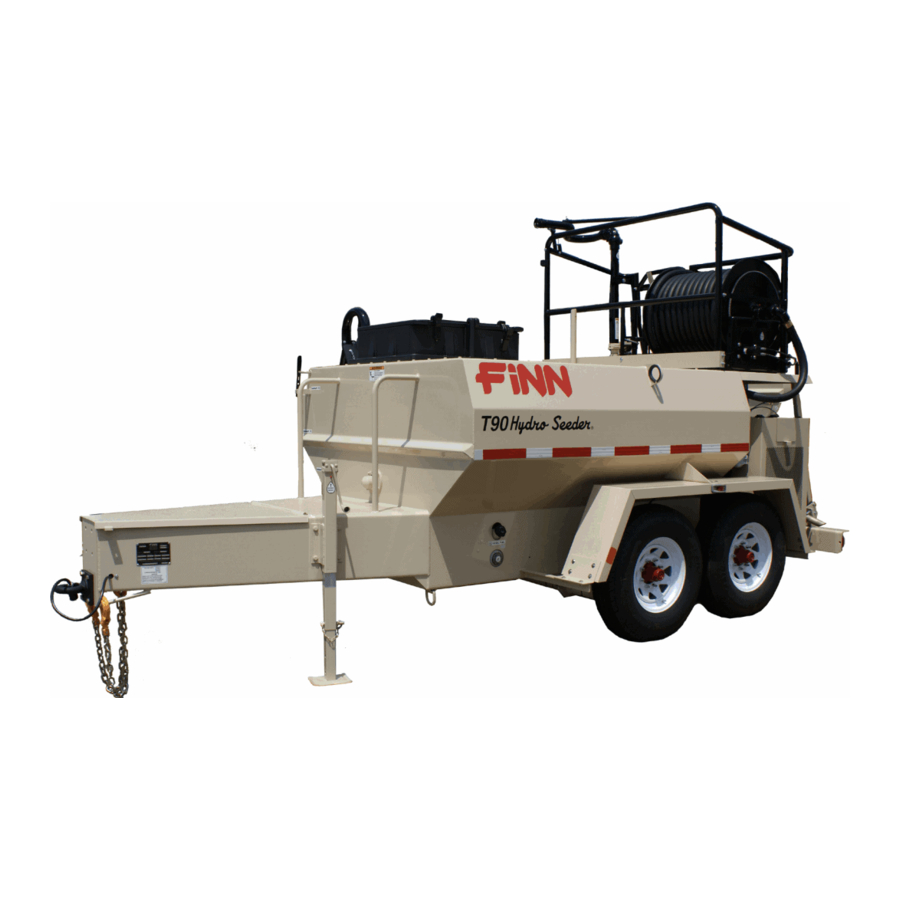
THE FINN T90 HYDROSEEDER ® This manual gives you step-by-step instructions for the operation and maintenance of the Finn T90 HydroSeeder For best results and to insure longer life of the equipment, please follow the instructions carefully. For your safety read the entire manual before operating this unit. -
Page 13: Attachments
Mounting the HydroSeeder® to the truck must allow for tire clearance as well as frame twist. Place hard wood spacers along the length of truck rails or use Finn spring mounting kit (#011562) or equivalent. ® C. Place chains over the HydroSeeder and around truck bed and secure with binders. -
Page 14: Pre-Start Check
® 3. Hose Reel. The live hose reel will mount either on the HydroSeeder or on the truck frame. The 200 foot (60.96 m)capacity electric rewind reel will wind up and store empty hose. It can be electrically ® connected to the HydroSeeder battery. - Page 15 Turn thumb nut clockwise until stem rises to maximum height. b) Remove cap and fill cap with sodium (water soluble) base grease. (FINN part num- ber 000698). DO NOT use lithium base (chassis lube) grease. c) Replace cap.
-
Page 16: Two Valve Operation
TWO VALVE OPERATION: The T90 HydroSeeder ® is equipped with two independently operated ball valves to control slurry flow. One is located in the recirculation line below the platform, and the other is located in the discharge line above the platform. - Page 17 CLOSED Figure 4- Discharge Through Boom or Extension Hose Through Boom 3. EXTENSION HOSE OR HOSE REEL THROUGH REMOTE PORT: Flow is through recirculation with no flow through closed discharge valve (Figure 3). Flow through extension hose is controlled by engaging and disengaging slurry pump clutch, or by remote valve at end of hose. Open recirculation valve allows flow back into tank.
-
Page 18: Starting Procedure
® The following tables on page 13 show loading versus coverage rates for the Finn HydroSeeder . Table A shows rates for “one step” applications. The coverage area is determined by the fiber mulch capacity of the ®... - Page 19 TABLE A USING SEED, FERTILIzER AND MULCH Unit Amount of Material in Tank (pounds(kilograms)) Coverage Area Seed Fertilizer Mulch (sq. ft.(sq.m.)) T90 II 92 (41) 107 (48.5) 400 (181) 11,600 (1,075) Above Table is based on 1,500 pounds (680.39 kg) of mulch, 400 pounds (181.44 kg) of fertilizer and 345 pounds (156.49 kg) of seed ((8 pounds (3.6287 kg)/1000 square feet) per acre.
-
Page 20: Tank Capacity Chart
T90 II Gallons in. (cm) from in. (cm) from (Liters) bottom 800 (3028) 10 (25.4) 42 (106.7) 835 GALLONS 750 (2839) 12.25 (31.1) 39.75 (101.0) 700 (2650) 14.25 (36.2) 37.75 (95.9) 650 (2460) 16.25 (41.3) 35.75 (90.8) 600 (2271) 18.25 (46.4) 33.75 (85.7) 550 (2082) 20.25 (51.4) - Page 21 3. Piping System Cleanout Procedure (Purging Line): A. Remove discharge nozzle and gasket from discharge boom. B. Aim discharge boom assembly into an open area away from any persons, obstructions or high voltage power lines. C. Open discharge valve and close recirculation valve. D.
-
Page 22: Prior To Application
PRIOR TO APPLICATION: 1. Operator should familiarize self with area to be seeded and develop a plan to insure uniform applica- tion. 2. Develop a plan for communication between operator and driver of the carrying or towing vehicle to sig- nal for start, stop, turn, etc. -
Page 23: Ii. Discharge Through The Boom
4. Generally the most remote area of the seed bed should be covered first. Distance is controlled by engine speed and nozzle selection. Do NOT partially close the valve to control the distance. 5. While moving along area to be seeded, the operator should move the nozzle back and forth in a slow, even arc. -
Page 24: Reloading Procedure
B. EXTENSION HOSE SYSTEM - WITHOUT REMOTE VALVE: 1. Connect the extension hose into the end of the discharge boom. 2. A person controlling the end of the hose directs a second operator at the machine to control the clutch and adjust the engine speed. - Page 25 7. Engage the clutch, and move the throttle to full engine speed. A stream of water should be coming from the end of the recirculation pipe beside the hatch opening, as well as from the boom. 8. As soon as both streams are clear, close the discharge valve and make sure water is being recirculated back to the tank.
-
Page 26: Cleaning And Maintenance
CLEANING AND MAINTENANCE: AFTER FIRST 4-8 HOURS OF OPERATION: 1. Check and adjust clutch - see page 27. 2. Re-torque wheel lugs - again after 7 days. (Trailer option only). DAILY: ® 1. Cleaning the HydroSeeder A. Fill the slurry tank to the center of the agitator shaft. B. -
Page 27: Seasonal & Winter Storage Maintenance
12. Add fuel stabilizer to fuel tank. HYDRAULIC SYSTEM: The hydraulic system on your Finn HydroSeeder® is designed to give trouble free service, if maintained. The most important areas of maintenance are the hydraulic oil and filtration. The reservoir holds 19 gallons of ISO Grade 46 hydraulic oil. - Page 28 VIEW SEE VIEW (Showing Hose Reel) Figure 7 - Lubrication & Adjustment Points...
-
Page 29: Lubrication & Fluids Chart
LUBRICATION AND FLUIDS CHART (Reference Figure 7) Ref. No. Location Lubricant Frequency Number Check Grease Level in Pressure Lubricator Daily Check Clutch Lever Bearings Daily Grease Agitator Shaft Bearings Daily Grease Discharge Swivels Daily Check Engine Oil Level Daily Change Engine Oil and Filter See Engine Manual Grease Pump Bearings Weekly... - Page 30 CLUMP MAINTENANCE: CAUTION: Clump maintenance should to be done only while engine is not running, and battery cables are disconnected. Figure 8 - Clump Assembly Components...
- Page 31 CLUTCH/PUMP ASSEMBLy (Reference Figures 8 and 9) Ref. No. Part Number Description No. Req’d 005146 Suction Cover X0824SS Suction Cover Bolt Y08SS Suction Cover Nut 006437 O-Ring 005543 Impeller 006443 Mechanical Seal Assembly 005144 Pump Casing X0824SS Suction Cover Bolt W08FSS Suction Cover Washer 006444 Grease Retainer Seal 005446...
- Page 32 PUMP MAINTENANCE SECTION: (Reference Figures 5 and 6) CAUTION: Pump maintenance to be done only while engine is not run- ning, and battery cables are disconnected. Figure 9 - Cross-Section Through Clump A. FACTORY-TOLERANCES. 1. To check pump tolerances loosen the two clamps on the pump suction piping and remove the inlet elbow. Through the pump suction hole, insert a feeler gauge between the pump impeller (3) and the suction cover (1).
- Page 33 C. CLEANING. 1. To clean pump impeller (3), loosen the two victaulic pipe clamps and remove the suction pipe assembly. The eye of the impeller can then be seen through the suction cover plate (1) and is readily accessible for cleaning. 2.
- Page 34 HANDLE PRESSURE: Variation in handle length directly affects the pressure required at the handle for proper clutch adjust- ment. See the table below to determine the correct handle pressure. Reference Pressure Clutch Size Handle Length at Lever 7-1/2" 7-5/8" 110 to 130 Lbs IMPORTANT: A new clutch generally requires several adjustments until the friction surfaces are worn in.
- Page 35 1. Disengage the clutch operating lever and remove the old facing plates (30). 2. Insert the new facing plates (three segments) in between the clutch body (34) and the pressure plate (29), and center the facings as close as possible. 3.
- Page 36 2. Plugging or clogging: DANGER: Turn off engine and disconnect battery cables before working on equipment. Serious injury or death can result from moving parts or high pressure spray. Sometimes when a stoppage occurs, you will not be able to find anything in the line. When this happens, it means that the system became airbound instead of plugged. To remedy this, see “Foaming”. Plugging can occur in any one of four places;...
- Page 37 ® TROUBLE SHOOTING YOUR HYDROSEEDER Problem Probable Causes Suggested Solutions LEAKS: Tank bearing Leaks. Lack of lubrication - seal Replace seal and follow lube worn. schedule. Bolts not tightened. Tighten uniformly to 25 ft. lbs. Properly. Pressure Clamps. Rubber seal cracked, Replace, always grease seal before pinched or torn.
- Page 38 ® (CONTINUED) TROUBLE SHOOTING YOUR HYDROSEEDER Problem Probable Causes Suggested Solutions CLUTCH CONT’D: Pump looses prime - Pump worn. Reset pump tolerance page 22. lacks distance - leaves excessive amount in Suction partially plugged. Clean out machine see page 16. tank (100 gal (378 liters) or more).
- Page 39 ® (CONTINUED) TROUBLE SHOOTING YOUR HYDROSEEDER Problem Probable Causes Suggested Solutions PUMP: Excessive wear. Fertilizer with highly Change fertilizer. Avoid abrasive abrasive filler. fillers. Overloading machine Load machine to recommended with dry material. capacities. Too much time allowed After loading and mixing has been between loading and completed, set agitator at 1/2 speed discharging.
- Page 40 T90 SKID-MOUNT HYDROSEEDER® TECHNICAL SPECIFICATIONS 6′8″ (203 cm) 11′0″ (355 cm) 8′5″ (257 cm) T90 TRAILER HYDROSEEDER® TECHNICAL SPECIFICATIONS 7′1″ (216 cm) 16′2″ (493 cm) 9′0″ (274 cm)
- Page 41 FINN T90 HYDROSEEDER® TECHNICAL SPECIFICATIONS POWER ............Diesel Kubota V1505, 33.5 hp (25 kw), 4 cylinder water-cooled ENGINE SAFETY SYSTEM ......Low oil pressure, high temperature shutoff TANK SIZE ............940 gallon (3,558 liter) liquid capacity 800 gallon (3,028 liter) working capacity FUEL TANK CAPACITY ........
- Page 42 NOTES...
- Page 43 HydroSeeder ® Parts Manual Model SR...
- Page 44 T90 TRAILER PICTORIAL REFERENCE OPERATOR’S PLATFORM HOSE REEL Operator’s Platform ......Pages 44-45 Discharge Boom Assembly....Pages 58-59 Hose Reel Assembly ......Pages 54-57 Control Box Wiring......Pages 60-61 Nozzles, Remote Valve & Tool Kit ... Page 69 TRAILER Trailer ..........Pages 40-41 Wheel &...
- Page 45 T90 SKID PICTORIAL REFERENCE OPERATOR’S PLATFORM HOSE REEL Operator’s Platform ......Pages 44-45 Discharge Boom Assembly....Pages 58-59 Hose Reel Assembly ......Pages 54-57 Control Box Wiring......Pages 60-61 Nozzles, Remote Valve & Tool Kit ... Page 69 SKID PIPING, CLUMP & ENGINE Skid...........
-
Page 46: Wheel & Hub Assembly
VIEW C VIEW B VIEWS E & F (Page 41) VIEW B VIEW D (Page 41) VIEW A WHEEL & HUB ASSEMBLY (See Pages 46-47) VIEW A (See Page 41) WHEN ORDERING PARTS, BE SURE TO STATE SERIAL NUMBER OF MACHINE LBT90-SR Rev. A... - Page 47 VIEW E VIEW F VIEW D 39, 40 & 41 TRAILER Ref. No. Part Number Description No. Req’d 080701 Jack Weldment w/Bracket 080043 Lunette Eye 2-1/2" Pintle Hitch OPTIONAL 005134 2-5/16" Ball Coupler 005135 2-5/16" Ball F90-0020 Tank Top F120-0006 Hatch Safety Rail 012834 Bag Cutter - Stainless Steel 012833...
- Page 48 OPERATOR’S PLATFORM (See Pages 44-45) VIEW A (See Page 43) WHEN ORDERING PARTS, BE SURE TO STATE SERIAL NUMBER OF MACHINE LBT90-SR Rev. A...
- Page 49 VIEW A SKID Ref. No. Part Number Description No. Req’d 012833 Poly Hatch Assembly 012834 Bag Cutter - Stainless Steel F90-0021 Tank Top F120-0006 Hatch Safety Rail 005600 Right Rear Rail 005596 Slide Gate 005652 Front Cross Rail 052136-07 Rubber Mount Pad 005598 Left Rear Rail 005698 Tool Box Mount Weldment...
- Page 50 VIEW B VIEW A VIEW C WHEN ORDERING PARTS, BE SURE TO STATE SERIAL NUMBER OF MACHINE LBT90-SR Rev. A...
- Page 51 VIEW D VIEW E OPERATOR'S PLATFORM Ref. No. Part Number Description No. Req’d 005538 Right Rear Rail Weldment 002258 Clamp Handle Weldment 012487-05 Boom Clamping Strap 005161 Rubber Strap w/S-Hooks 005533 Gate Weldment 005532-03 Spacer 012052 Gate Spring 005532-05 Hinge Mounting Strap 005462-03 Platform Right Toe Rail 005540 Left Rear Rail Weldment...
- Page 52 See 26 See 26 See 26 WHEN ORDERING PARTS, BE SURE TO STATE SERIAL NUMBER OF MACHINE LBT90-SR Rev. A...
- Page 53 WHEEL AND HUB ASSEMBLY Ref. No. Part Number Description No. Req’d 005637 Axle Assembly (Includes Hub, Drum & Brakes) 005060A Mounted Tire Assembly 005060R Radial Tire 1 per 005057 Wheel, 16.5 x 6.75 1 per WL0190016 9/16 Lug Nut 8 per WL8-219-4 Hub and Drum Assembly WL605 Grease Cap 1 per...
- Page 54 BEARING ASSEMBLY NOTE: BEARING ASSEMBLY (ITEM #1) INCLUDES ITEMS #2 THRU #11. AGITATOR SHAFT THROUGH BACKSIDE NOTE: TO TIGHTEN, TURN NUT NOT BOLT. TORQUE TO OUTSIDE 25 FT. LBS. OF TANK WALL DO NOT OVER TORQUE. AGITATOR SHAFT ASSEMBLY NOTE: AGITATOR SHAFT ASSEMBLY (ITEM #12) INCLUDES ITEMS #13 THRU #23.
-
Page 55: Agitator Assembly
AGITATOR ASSEMBLY Ref. No. Part Number Description No. Req’d 007420 Bearing & Seal Assembly (Includes Items 2 Thru 11) 0Y08SS Agitator Nut 4 per 012605 Bevel Sealing Washer 4 per 007211 Flangette w/Lube Coupling 1 per 007705 Grease Fitting 1 per 003022 Bearing 1 per 007212 Flangette... -
Page 56: Hydraulic Agitator Drive
*NOTE: See Page 52 For Hydraulic System Schematic. HYDRAULIC AGITATOR DRIVE Ref. No. Part Number Description No. Req’d 070660 Hydraulic Motor 070660K 1/4" x 5/16" x 1-1/2" Key 005463 Torque Arrestor Plate 004630 Rubber Bushing X0824 1/2-13 UNC x 1-1/2" Lg. Hex Hd. Cap Screw Y08L 1/2-13 UNC Lock Nut 023156... -
Page 57: Trailer Wiring
LH BRAKE ASSY TRAILER PLUG (See Pages 40-41) TAIL LIGHTS (BROWN) NOT USED RIGHT LEFT WHITE BROWN TURN TURN (GREEN) (YELLOW) BLACK GROUND ELECTRIC BRAKES (WHITE) (BLACK) BROWN BROWN WHITE STARTER BLACK WHITE BROWN RH BRAKE ASSY (See Pages 46-47) TRAILER WIRING Ref. No. - Page 58 WHEN ORDERING PARTS, BE SURE TO STATE SERIAL NUMBER OF MACHINE LBT90-SR Rev. A...
-
Page 59: Hydraulic System
HYDRAULIC SYSTEM Ref. No. Part Number Description No. Req’d 005639 Female NPT Elbow 005640 MNPT - FJIC Adapter 005757 MSAE - FJIC Adapter 005794 MSAE - MJIC 90° Elbow 008690 FJIC - FNPT Adapter 012044 Pressure Gauge 012086 MSAE - MJIC Adapter 023616 MNPT - MJIC Adapter 052095 Swivel Branch Tee... - Page 60 VIEW A WHEN ORDERING PARTS, BE SURE TO STATE SERIAL NUMBER OF MACHINE LBT90-SR Rev. A...
- Page 61 HYDRAULIC HOSE REEL ASSEMBLY (OPTION) Ref. No. Part Number Description No. Req’d 008212A Hose Reel 080302 Flanged Riser 080302G Hose Reel Riser Gasket 008144 Hose Reel Ring Gear 008200 Hose Reel Chain w/Connecting Link - 69" Lg. 008433 Pin Lock w/Brackets Assembly 008313 Idler Side Bearing 008314 Drive Side Bearing...
- Page 62 WHEN ORDERING PARTS, BE SURE TO STATE SERIAL NUMBER OF MACHINE LBT90-SR Rev. A...
- Page 63 HyDRAULIC SySTEM w/HOSE REEL Ref. No. Part Number Description No. Req’d 008696 SAE Reducer 012871 SAE Reducer 012872 SAE Reducer 012873 MSAE - FJIC Swivel Adapter 023621 MSAE - MJIC 90° Elbow 055274 MSAE - MJIC 90° Elbow 055308 MSAE - MJIC Adapter 055359 MSAE - MJIC Adapter FW65217 MSAE - MJIC Adapter FW71869...
- Page 64 NOTE: ITEM #1 INCLUDES ITEMS #2 - 9. WHEN ORDERING PARTS, BE SURE TO STATE SERIAL NUMBER OF MACHINE LBT90-SR Rev. A...
- Page 65 DISCHARGE BOOM ASSEMBLY Ref. No. Part Number Description No. Req’d 005529 Discharge Boom Assembly Consisting of: 006102 2” Female Coupler 006514 2" Coupler Gasket 005734 Boom Pipe Weldment Z0632SCP Boom Handle Set Screw 005528-03 Boom Collar Weldment Z0612SCP Boom Collar Set Screw 007286 Discharge Boom Balance Spring 007288 2”...
- Page 66 BLACK GROUND GREEN TIMER HOURMETER HORN GLOW PLUG INDICA T OR BLACK LIGHT BLACK BLUE BLUE 13 (-) 14 (+) BLUE SAFETY SWITCH BROWN RED/BLACK BLUE Brown/ Y ellow/ Blue Black Black Y ellow Black Black/ Orange Brown Orange/ Blue/ Red/ Black Black...
-
Page 67: Control Box Wiring
CONTROL BOX WIRING Ref. No. Part Number Description No. Req’d 005604A Control Box Assembly 007274 Hour Meter 022119 Safety Switch KU15694-65990 Glow Plug Timer 020886 Horn Button KU15403-64490 Glow Plug Indicator Light 006245 Generator Light KU66711-55131 Ignition Key Switch KU66711-55140 Ignition Key - Set of 2 023604 Electrical Housing 023601... - Page 68 CLUTCH/PUMP (See Pages 64-65) WHEN ORDERING PARTS, BE SURE TO STATE SERIAL NUMBER OF MACHINE LBT90-SR Rev. A...
-
Page 69: Piping
PIPING Ref. No. Part Number Description No. Req’d 005682 Clutch/Pump Assembly (See Pages 64-65 for Parts) 002383 Pressure Lubricator 005470 Pump Shaft Guard 006144 Pipe Clamp 006145 Clamp Gasket 006359 90° Pipe Elbow 005524-02 Suction Pipe Elbow Weldment 008280 Suction Line Shut-Off Valve 005523-06 Connector Pipe 006710... - Page 70 WHEN ORDERING PARTS, BE SURE TO STATE SERIAL NUMBER OF MACHINE LBT90-SR Rev. A...
-
Page 71: Clutch/Pump Assembly
CLUTCH/PUMP ASSEMBLy Ref. No. Part Number Description No. Req’d 005682 Clutch/Pump Assembly Consisting of: 005146 Pump Suction Cover 005150 O-Ring 005543 Pump Impeller 006443 Mechanical Shaft Seal 005144 Pump Casing 006444 Grease Retainer Seal 005446 Flange Pilot Bearing 005447 Shaft Seal 005475 Thrust Bearing Retainer 005544-02 Bearing Retainer Gasket 005670... - Page 72 DETAIL A DETAILS B, C & D (See Page 67) WHEN ORDERING PARTS, BE SURE TO STATE SERIAL NUMBER OF MACHINE LBT90-SR Rev. A...
-
Page 73: Engine & Radiator
DETAIL C DETAIL B DETAIL D 18 (REF) 33 34 ENGINE & RADIATOR Ref. No. Part Number Description No. Req’d 031354 Air Cleaner Assembly KU15741-11080 Air Filter Element KU01123-50835 Bolt 055548 Mounting Band 022450 2-1/2" Worm Gear Clamp KU16616-11621 Air Cleaner Inlet Pipe (1 x 180 Deg. Elbow cut to make 2 x 90 Deg. Elbows) 005681-07 Air Cleaner Extension Pipe F90-0012... -
Page 74: Engine Wiring
FUEL PUMP GLOW PLUGS WHITE WHITE BLUE SHUT DOWN HORN SYSTEM TEMPERATURE SWITCH SWITCH BROWN ALTERNATOR HOSE REEL LEAD 16 Ga. Orange Brown Green Blue 12 Ga. Black BROWN ORANGE BLACK BLUE Blue Black Green Yellow 12 Ga. 16 Ga. GROUND STRAP YELLOW... - Page 75 HOSE REEL NOzzLE/REMOTE VALVE/TOOL KIT Part Number Description No. Req’d HOSE REEL NOzzLES 080273 Long Distance Hose Reel Nozzle Assembly 080131 Long Distance Nozzle 1 per 080260 Adapter 1 per 160749 Reducer Bushing 1 per 080394 Wide Fan Hose Reel Nozzle Assembly 006604 Wide Fan Nozzle 1 per 080260 Adapter 1 per...
- Page 76 WHEN ORDERING PARTS, BE SURE TO STATE SERIAL NUMBER OF MACHINE LBT90-SR Rev. A...
- Page 77 DECALS R ef. No. Part Number Description No. Req’d 023174 "FINN" Decal - Large 012661-05 "T90" Decal 011595 "Hydro Seeder" Decal 022199 "Throttle" Decal 011567 "Do Not Aim . . ." Decal 007230-02 "Service Daily" Decal 007230 "Service Daily" Decal 023391 "Diesel Fuel Only" Decal...
Need help?
Do you have a question about the T90-II HydroSeeder and is the answer not in the manual?
Questions and answers