Advertisement
Quick Links
the note at the end of the manual.
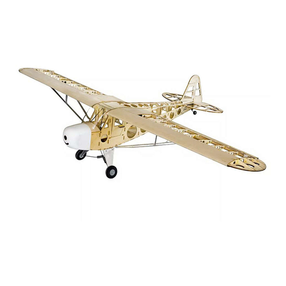
Historical Background
lightweight design which gives it good low-speed handling properties and short-field performance.
many of these beloved airplanes are still around today.
Specification
Suggested Equipment
Suggested
4
or more
asoline
Advertisement

Subscribe to Our Youtube Channel
Related Manuals for H-KING Piper J-3 Cub V2.0


Summary of Contents for H-KING Piper J-3 Cub V2.0
- Page 1 the note at the end of the manual. Historical Background lightweight design which gives it good low-speed handling properties and short-field performance. many of these beloved airplanes are still around today. Specification Suggested Equipment Suggested or more asoline...
-
Page 2: Safety Precautions
SAFETY PRECAUTIONS This product should not be considered a toy, but rather a complicated and sophisticated flying model. Your safety depends on how you use and fly it, if not correctly operated it could cause injury to you or your family members. Children must be accompanied by an adult at all times if operating this product. - Page 3 Tools required Please sand all parts before Assemble the Fuselage 01-1 F36-2 F36-4 Align F37-1 F36-4 F36-3 fuselage side 01-3 01-4 Align Align F37-1 Align F0-3 Align F36-4...
- Page 4 01-5.1 Balsa strip to actual length 01-3 01-5 01-5.3 01-5.4 Blind nuts 01-5.2 Blind nuts F19-1 Fiberglass blind nut is installed as shown in Please blind nut faces into the the picture wrong fuselage side as this will Assemble the finished fuselage sides that were built install the inner balsa strip for 01-4...
- Page 5 01-8 01-11 01-9 01-12 01-13 01-10 Glue 01-14 01-15 01-16 01-17...
- Page 6 01-18 01-19 01-20 01-21 Assemble the Main Wing Pay attention to the direction of the blind nuts Blind...
- Page 7 intermediate strut brace fixing Assemble the horizontal and vertical 03-1 03-2 03-3 Glue parts T13 to the vertical stabilizer and to each elevator half at the points A,B and C as shown. 03-4 03-5 has been drilled into the end of each T13 part. both halves do lie flat.
- Page 8 03-6 03-7 the positions shown. nsert the Assemble the horizontal and vertical tail wheel to the fuselage 04-1 04-2 Horizontal Insert the elevator into the rear of the fuselage as shown and glue the elevator joining rod into position. 04-3 04-5 Bend the steel wire onto the tailwheel wire...
- Page 9 04-7 04-6 Vertical Tail 04-8 Assemble the Landing Gear 05-1 05-2 Outside Inside Outside 05-3 05-4 Inside 06-1 . See note at end of manual.
- Page 10 Install the servo inside the wing 06-2 06-3 06-4 Sand to Install the wing strut 06-5 Sectional view 06-6 06-7...
- Page 11 Install servos and pushrods inside the fuselage Glue after the steel wire rod and the servo arms If fitting an I.C. motor then see the steps below for a different servo arrangement.
- Page 12 Install the motor mount and electric/IC motor on the other side...
- Page 13 Set and Adjust For initial flights we recommend you balance the model on the 85mm mark to make it more docile. Once you have flown it a few times you can then move it back slightly if you wish, this will make the flying characteristics more agile.
- Page 14 C of G: Aileron Elevator Rudder OPTIONAL Install the scale parts Install the scale engine parts...
- Page 15 Wiring Diagram for RC Equipment (Electric powered only) Wiring Diagram for RC Equipment (IC Engine only) Engine Throttle...
- Page 16 SIDE VIEW SIDE VIEW to the right FRONT VIEW to the left FRONT VIEW Rudder stick to the right FRONT VIEW Rudder stick to the left FRONT VIEW Note: This instruction manual shows the construction of the wooden airframe and the installation of the RC equipment.
Need help?
Do you have a question about the Piper J-3 Cub V2.0 and is the answer not in the manual?
Questions and answers