Advertisement
Quick Links
Advertisement

Subscribe to Our Youtube Channel
Related Manuals for H-KING Cloud Clipper


Summary of Contents for H-KING Cloud Clipper
- Page 1 BUILDING INSTRUCTION...
- Page 2 WARNING Please read this instruction manual fully and become completely familiar with the features of this product before operating. Failure to operate this product correctly could result in damage to the product, personal property and cause serious injury. This is a sophisticated hobby product and is NOT a toy. It must always be operated with caution, common sense and some basic mechanical ability.
- Page 3 Contents: PRODUCT LIST KIT FEATURES , SPECIFICATIONS BUILDING INSTRUCTION 1) FUSELAGE ASSEMBLY P.3-P.23 2) WING P.24-P.30 3) EMPENNAGE P.31-P.35...
- Page 4 PRODUCT LIST: • Plywood sheet pack x 1 pc • Metal fitting pack x 1 pc • 1:1 drawing plan • A set of landing gear x 1 pc • A set of pinewood stringer • A pair of high-quality rubber main wheels •...
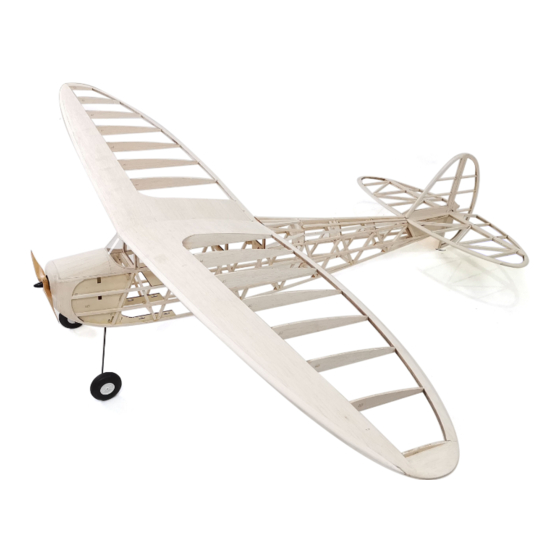
- Page 5 3S Li-Po battery Building instruction: This Cloud Clipper kit includes precision pre-cut wing ribs, plywood formers, balsa wood strips/ sheets/blocks for the wing and stabilizers. Hardwoods and dowels for the fuselage, a set of piano wire landing gear, a set of wheels, a hardware accessories pack, and a complete set of full size building plans.
- Page 6 BUILDING INSTRUCTIONS 1 FUSELAGE ASSEMBLY: We recommend that you cover this part of the plan using clear food wrapping film and scotch tape. Do this before pinning and gluing the balsa down in the required positions, this will keep the plan clean and intact. 1) The supplied 6 x 6mm balsa strips for the fuselage require joining and extending.
- Page 8 3) Glue to the fuselage frame part B15 which reinforces the nose section as shown. Do this to both the left and right hand fuselage sides. You will need to soak the balsa at the front of the the bottom longeron to enable it to bend to the underneath shape of B15.
- Page 9 4) Glue parts B19 to all the frame joints as shown, ensure you continue to make a left and right hand fuselage side.. Add 3mm balsa sheet to the tail as shown below to form the push-rod exit, again, ensure you are making a left and a right hand side.
- Page 11 5) Add a piece of 8mm balsa sheet to the nose of both the left and right hand fuselage sides.
- Page 12 6) Glue former B13 and B14 together with epoxy glue. Use some mini clamps to hold them whilst the glue sets.
- Page 13 7) Laminate together the two B25 parts to form the front former for the motor mount. 8) Glue B25 and B13/B14 to the right hand fuselage side as shown. Note: Ensure both formers remain perpendicular to the fuselage side as the glue sets.
- Page 14 9) Now assemble the left hand fuselage side to the right hand fuselage side. Use some mini clamps to hold the assembly together. Ensure both formers remain perpendicular and square to the left and right fuselage frame as the glue sets.
- Page 15 10) Place the fuselage over the plan and bring the tail together as shown below, add parts B20 and B26, clamp these together as the glue sets. Add balsa strips to the top and bottom of the fuselage frame so that the fuselage sides follow the contour shown on the plan. You will need to cut the balsa strips to the lengths shown on the plan to ensure the contour is followed precisely.
- Page 16 11) Add the balsa longerons to the fuselage sides as shown.
- Page 17 12) Add the formers to the top of the fuselage as shown below and on the plan.
- Page 18 13) Add the balsa stringers to the formers to form the turtle deck etc. Ensure all the formers are positioned correctly according to the plan.
- Page 19 14) At this point it is best to install the push-rod tubes into the fuselage. Trim the excess push-rod tubes where they exit the rear of the fuselage.
- Page 20 15) Install the B17 servo mounting plate into the fuselage.
- Page 21 16) Install and glue 8mm balsa sheet to the lower part of the fuselage nose, then sand to shape.
- Page 22 17) To make the battery hatch, assemble B21, B22, and B23 together as shown. Then plank the top with a piece of 2mm balsa sheet, trim and sand to shape. Glue two 3 x 4 mm magnets into the two holes in former B21.
- Page 23 19) Glue former B24 into place, then plank the top using 3mm balsa sheet as shown below. Trim, shape, and sand the sheeting according to the plan.
- Page 25 20) Shape a piece of 8mm balsa sheet to make the tail skid fairing and glue to the rear of the fuse- lage. Make a hole with a 1.5mm drill bit as shown, and glue the tail skid wire into place to form the landing skid.
- Page 26 2 WINGS ASSEMBLY: We recommend that you cover this part of the plan once again using clear food wrapping film and scotch tape. Do this before pinning and gluing the balsa down in the required positions, this will keep the plan clean and intact. 1) Identity all the wing parts (trailing edge, leading edge and wing ribs ) as shown.
- Page 27 2) The leading edge strips need to be joined to extend the length, join these together as shown below.
- Page 28 3) Ensure your building board is perfectly level and flat before you assemble the wing to ensure no warping. Assemble the wing ribs, wing spars, leading edge and trailing edge together as shown. Use CA glue to hold everything in place, and glue the A19 reinforcement balsa sheets in between the spars as shown.
- Page 29 4) Fit and glue the 8mm balsa sheet wing tips. 5) Plank the leading edge with the balsa sheets supplied.
- Page 30 6) Install and glue the balsa leading edge to the wing, use some masking tape to hold it in place as the glue sets, see below.
- Page 31 7) Sheet the upper, lower, and mid section of the wing with the balsa sheets supplied.
- Page 32 8) Trim and sand the leading and trailing edge of the wing to the required shape as shown.
- Page 33 9) Trial fit the wing joiner into the wing slot and trim to fit where necessary. 10). Repeat above steps to make another set of wings. Note: Ensure you are building a set of LEFT and RIGHT hand wings.
- Page 34 EMPENNAGE Again, we recommend that you cover this part of the plan using clear food wrapping film and scotch tape. Do this before pinning and gluing the balsa down in the required positions, this will keep the plan clean and intact. 1.
- Page 35 2. Identity all parts for the elevator and assemble as shown using CA glue to bond everything together, trim and sand all joints as necessary. Use a hobby knife to make some slots for the hInges, and assemble together both the elevator and stabilizer, use the paper hinges supplied in the kit.
- Page 36 3. Identity all parts for the fin and rudder assemblies as shown, use CA glue to bond everything together, trim and sand all joints as necessary. Use a hobby knife to make some slots for the hInges, and assemble together both the fin and rudder, use the paper hinges supplied in the kit.
- Page 37 4. Trial fit the horizontal stabilizer onto the fuselage as shown on the plan. Sand as necessary to achieve a good fit and to ensure it is square and level to the fuselage. Once satisfied with the fit, glue into place using a good slow setting epoxy, ensure it remains square and level as the glue sets.
- Page 38 Apply slow setting epoxy, keep checking the alignment whilst the glue dries. Your Cloud Clipper is now ready for covering. Cover the model with your choice such as a good quality film or textured covering.
Need help?
Do you have a question about the Cloud Clipper and is the answer not in the manual?
Questions and answers