Table of Contents
Advertisement
Quick Links
Advertisement
Table of Contents

Subscribe to Our Youtube Channel
Related Manuals for EOS Farblichtmodul


Summary of Contents for EOS Farblichtmodul
- Page 1 Assembly instruction Farblichtmodul Druck Nr. 29343325en/ - 43.06...
- Page 2 General security rules l Installation of electrical equipment should only be carried out by authorised electrician. l Regulations of public ullity (EVU) as well as appropriate VDE-rules (DIN VDE 0100) must be abided. l Attention! Danger for life! Please do not repair and install the equipment yourself.
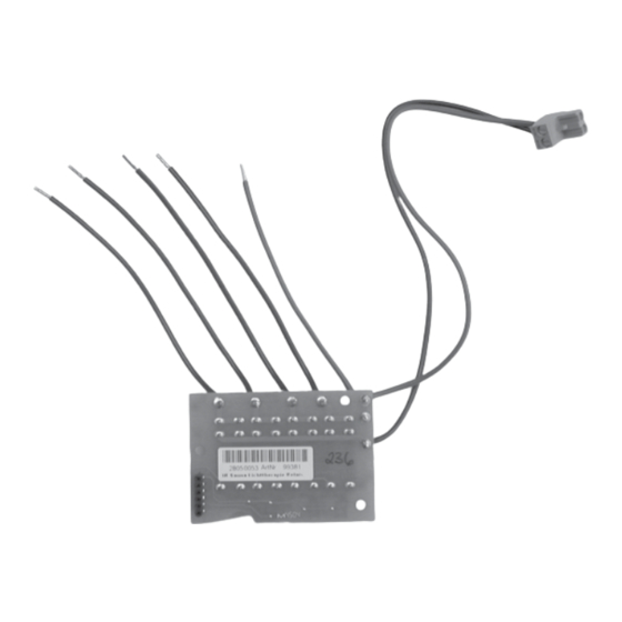
- Page 3 Mounting of coloured light module (ArtNr. 942761) in control unit EMOTEC HCS 9003 Please open the control unit just as described in the assembly instruction. Please establish the electrical connection. - The power supply line for the coloured light module (longish wire) should be connected with the clamps below the clamps for transformer.
- Page 4 Fix the coloured light module with the attached screw. safety screws Attention: plug border Fig. 5 Contact pins should catch the pin border. Starting up Please find the appliance of coloured light modules in the instruction of the appropriated control unit EMOTEC HCS9003 / DC9000.
- Page 5 Open the clamp plate Lift the clamp plate and turn it up. Fig. 8 Make plug connection plug socket (double-pole) pins Connect the plug socket of coloured light module with the pins of the plug at the mainboard (fig. 9 and 11). Fig.
- Page 6 Connect the plug Insert the double-pole plug in the appropriate socket at the mainboard (see fig. 6) . Fig. 11 Install the clamp plate masked Reinstall the clamp plate. It must be catched into the 4 pins of the plug. Fig.
- Page 7 Connection of cable Please connect the cables with the upper clamps sequential from left to right according to the clamps inscription. N - red- yellow - green - blue Fig. 14 Mounting of coloured light appliance Connect the coloured light appliance with those clamps which are marked in the figure according to the clamps inscription.
Need help?
Do you have a question about the Farblichtmodul and is the answer not in the manual?
Questions and answers