
Related Manuals for McCrometer FPI Mag 394L


Summary of Contents for McCrometer FPI Mag 394L
- Page 1 Model 394L Full Profile Insertion Electromagnetic Flowmeter Quick Start Guide 24511-08 Rev. 1.0 February 2011...
- Page 2 Copyright © 1997-2011 McCrometer, Inc. All printed material should not be changed or altered without permission of McCrometer. Any published technical data and instructions are subject to change without notice. Contact your McCrometer representative for current technical data and instructions.
- Page 3 1.0 Safety 1.2 Safety Warnings When installing, operating, and maintaining McCrometer equipment where hazards may be present, you must protect yourself by wearing Personal Protective Equipment (PPE) and be trained to enter confined spaces. Examples of confined spaces are manholes, pumping stations, pipelines, pits, septic tanks, sewage digesters, vaults, degreasers, storage tanks, boilers, and furnaces.
-
Page 4: Site Selection
While the FPI-Mag is very flexible regarding its placement, when installing the sensor at a location with flow disturbers such as elbows, T-junctions, Y-junctions, and active valves, contact your local McCrometer representative for a site review and sensor location recommendation. - Page 5 4.4 Meter Disassembly For Installation When installing large meters, it can be desirable to remove the compression seal assembly from the rest of the meter and install it onto the valve separately. The following steps describe the separation of the sensor, top- plate and retaining rods from the compression seal assembly.
- Page 6 4.6 Meter Re-assembly After Compression Seal Assembly Installation 4.6.1 Apply liquid soap, such as Simple Green, to the interior surface of the seal gland. This will act as a lubricant to facilitate the insertion of the sensor and ensure its proper axial loading. Insert the sensor into the compression seal in the bottom plate while inserting the two retaining rods into their respective holes in the bottom plate and secure with 3/8"...
- Page 7 4.7.4 Insert the sensor into the pipe by simultaneously rotating the two captive nuts on the top plate clockwise with the two ratchet wrenches provided until the foot of the sensor reaches the far wall of the pipe and the load spring is compressed.
-
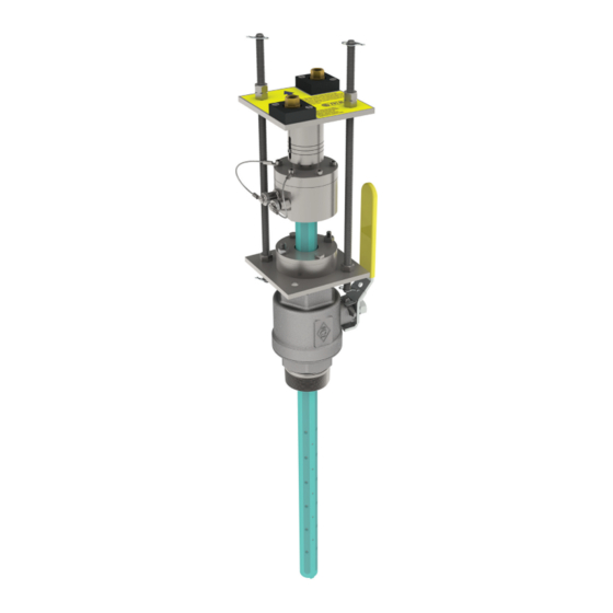
Page 8: Sensor Insertion Tool
4.8 Sensor Insertion Tool McCrometer recommends using a sensor insertion tool (P/N 75031) to help with inserting the sensor and to avoid any damage to the sensor. Place the profiling insertion tool over the captive nuts and lock it into place with spring locks located on the bottom of the tool. - Page 9 6.2 Installing Cables To Converter And Service Loop Conduit of any kind CANNOT be attached directly to the electronics enclosure. Attaching conduit directly to the enclosure will introduce dangerous gasses and moisture into the enclosure creating a dangerous condition, and will remove the enclosure's IP67 rating.
-
Page 10: Electrical Cable Connections
6.4 Electrical Cable Connections CAUTION Always disconnect the AC power cord before attempting any electrical connections. All electrical cables enter the unit through compression fittings located on the side of the converter. Ensure that all unused fittings are plugged so the case remains sealed. 6.5 Terminal Board All connections are made on the terminal board. - Page 11 6.7 4-20mA Hook-Up Isolated 4-20mA current loops are used to output flow data to external devices. Maximum load impedance is 1,000Ω, and the maximum voltage without load is 27VDC. The converter has the capability to detect a loss of load on this output. To disable this function set the value “mA Val. Fault” (Section: Main Menu, Sec.. 4.7) under the ALARMS menu to zero.
- Page 12 7.0 Converter Start-Up Before starting up the converter please verify the following: • Power supply voltage must correspond to that specified on the name plate • Electric connections must be wired as described in this manual • Ground connections must be properly installed When the instrument is powered and exhibits different operating conditions than those at the last shutdown, it initiates a verification cycle of the converter.
- Page 13 NOTES:...
- Page 14 3255 WEST STETSON AVENUE • HEMET, CALIFORNIA 92545 USA TEL: 951-652-6811 • 800-220-2279 • FAX: 951-652-3078 Printed In The U.S.A. Lit. #24511-08 Rev. 1.0/02-11 Copyright © 1997-2011 McCrometer, Inc. All printed material should not be changed or altered without permission of McCrometer. www.mccrometer.com Any published technical data and instructions are subject to change without notice.
Need help?
Do you have a question about the FPI Mag 394L and is the answer not in the manual?
Questions and answers