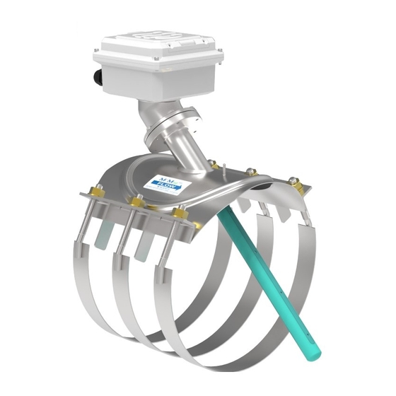
McCrometer Mc Mag3000 Installation, Operation And Maintenance Manual
Battery powered electromagnetic flow meter
Hide thumbs
Also See for Mc Mag3000:
- Installation and replacement (4 pages) ,
- Instructions (4 pages) ,
- Installation, operation and maintenance manual (32 pages)

Related Manuals for McCrometer Mc Mag3000


Summary of Contents for McCrometer Mc Mag3000
- Page 1 Mc Mag 3000™ Battery Powered Electromagnetic Flow Meter Installation, Operation and Maintenance Manual 30120-85 Rev. 2.0 August 13, 2019...
-
Page 2: Table Of Contents
Contents SAFETY . . . . . . . . . . . . . . . . . . . . . . . . . . . . . . . . . . . . . . . . . . . . . . . . . . . . . . . . . . . . . . . . . . . . . . . . . . . . . . . . . . . . 1 Safety Symbols . -
Page 3: Safety
Safety Warnings When installing, operating, and maintaining McCrometer equipment where hazards may be present, you must protect yourself by wearing Personal Protective Equipment (PPE) and be trained to enter confined spaces. Examples of confined spaces are manholes, pumping stations, pipelines, pits, septic tanks, sewage digesters, vaults, degreasers, storage tanks, boilers, and furnaces. -
Page 4: Introduction
2 .0 PRINCIPLE OF OPERATION The Mc Mag3000 uses Faraday's Law of Electromagnetic Induction to measure water velocity. Faraday's Law states that a conductor, moving through a magnetic field, produces a voltage. Charge carriers in the fluid produce a voltage when passing through a magnetic field. The magnitude of the voltage is directly proportional to the velocity at which the fluid moves through the magnetic field. -
Page 5: Installation
3 .0 INSTALLATION 3 .1 Packaging Note When you unpack the Mc Mag3000, you will find a red plastic cap over the front push button. This can be discarded with the rest of the packing materials. 3 .2 General Installation Considerations Proper meter installation is the first step to ensure excellent meter performance. -
Page 6: Straight Pipe Requirements
Installation 3 .4 Straight Pipe Requirements Flow meters are velocity sensing devices and are vulnerable to certain upstream disturbances. Because of this, meters need certain lengths of straight pipe before and after the meter. These distances relate to the diameter of the pipe used. -
Page 7: Flow Meter Installation
Installations Replacing Existing Saddle Meters The Mc Mag 3000 can be used to replace existing McCrometer saddle meters. The Mc Mag 3000 can be installed with Water Specialties bolt-on saddle meter cutout templates for 6” meters and 8”-20” meters, as well as with McPropeller bolt-on saddle meter cutout templates for 12”-16”... -
Page 8: Grounding
3 .6 Grounding The Mc Mag3000 is fitted with a grounding lug on the saddle for proper grounding. For typical installations the lug can be connected to an earth ground and/or the metal pipe in which it is installed. For electrically noisy installations connect the grounding lug to a dedicated, low impedance earth ground. Low impedance is 10 Ohms or less. -
Page 9: Converter Boot
Installation 3 .7 Converter Boot The Mc Mag 3000 comes with a boot to help protect the meter. NOTE: It is HIGHLY recommended that the boot be utilized at all times when the meter is not being read. The boot adds protection to the meter and insures proper closure of the lid, insuring the maximum battery life. -
Page 10: Operation
The Mc Mag 3000 comes pre-configured from the Factory based on the installation parameters provided to McCrometer at the time of order. Other than activating the display, there is nothing required of the user for the basic operation of the flow meter. - Page 11 Operation 4 .3 .2 Second Display Screen The second screen display shows the battery life remaining for both battery packs and the flow totalizer. In the sample below, both battery packs are at 99% and total flow is 500 kilogallons. Battery life remaining Totalizer Figure 9 .
-
Page 12: External Connectors
External Connectors 5 .0 EXTERNAL CONNECTORS 10-32VDC Power/4-20mA Output And Pulse Output The flow meter has one dedicated port and two optional ports on the back side of the electronics enclosure. The dedicated port (center) is used to download data logger information or for meter service and troubleshooting. The two optional ports are for: Optional 10-32 VDC power and 4-20mA output Optional pulse outputs (flow volume and alarms) -
Page 13: Dc Power Cable (Optional)
DC Power Cable (Optional) 6 .0 DC POWER CABLE (OPTIONAL) DC Power And 4-20mA Output Cable (Optional) The cable contains wiring for both the optional 10-32VDC power to the meter, and the 4-20mA output from the meter. See Figure 14 for the color scheme. Cable Jacket Black = -10-32 VDC Power (Negative) Red = +10-32 VDC Power (Positive) -
Page 14: Pulse Output Cable (Optional)
Pulse Output Cable (Optional) DC Power Supply Specifications Part Number: 115-12 Voltage – Input: 120 VAC ± 5% / 60 Hz (external fuse recommended) Voltage – Output: 12V ± 0.5 VDC @ 200mA Current – Output (Max): 200mA Power – 2.4W Environment: Operating Temperature: 0 to 55°C (21 to 130°F);... -
Page 15: Battery Removal And Replacement
Copyright © 2001-2019 McCrometer, Inc. All printed material should not be changed or altered without permission of McCrometer. Any published pricing, technical data, and instructions are subject to change without notice. Contact your McCrometer representative for current pricing, technical data, and instructions. - Page 16 Battery Installation and ™ Maintenance 3000 Replacement Shutting o the system IMPORTANT! You must follow the next steps in this speci c order to insure the unit does not reset the internal time clock. If you have the Data Logger Software and communication cable, disregard these next steps. The clock may be set with software once the unit is re-assembled.
- Page 17 Battery Installation and ™ 3000 Maintenance Replacement IV. Installing the batteries and restoring the power 11. If there is no strip of Velcro on the side of the chassis, remove the 12. Set the batteries in place, making sure clear adhesive protective strip from the small battery pack and press the wires extend toward the battery the entire battery pack in place as shown in the picture at right.
- Page 18 Battery Installation and ™ 3000 Replacement Maintenance V. Replacing the gasket If you installed replacement batteries, we recommend that you replace the gasket. If you installed new batteries, you must set the gasket in place before replacing the cover and closing up the unit. 17.
-
Page 19: Troubleshooting
Troubleshooting 9 .0 TROUBLESHOOTING If you see a message on the display of the converter, use the following table to begin troubleshooting. ALARM MESSAGE POSSIBLE CAUSE / CORRECTIVE ACTION The measured board temperature is out of the allowed range. Ensure that the instrument B.TEMP.OUT R. -
Page 20: 10 .0 Specifications
Lit. # 30121-41, Rev. 1.8 / 4-2-18 Copyright © 2014-2018 McCrometer, Inc. All printed material should not be changed or altered without permission of McCrometer. Any published technical data and instructions are subject to change without notice. Contact your McCrometer representative for current technical data and www.mccrometer.com... -
Page 21: Dimensions And Weights
DIMENSIONS AND WEIGHTS 11 .0 DIMENSIONS AND WEIGHTS Nominal Pipe Size Max/Min Flow And Weight 4" 6" 8" 10" 12" Maximum Flow U.S. GPM 1350 2350 3700 5300 Minimum Flow U.S. GPM Approximate Shipping Weight lbs. Nominal Pipe Size Dimensions (Inches) 4"... - Page 22 DIMENSIONS AND WEIGHTS 6.44" 4.34" 4.12" 6.44" Figure 18 . Enclosure Top View Figure 19 . Enclosure Front View 8.9" Flow Direction Figure 20 . Enclosure Height Page 20 30120-85 Rev. 2.0 | 13AUG2019...
-
Page 23: 12 .0 Returning A Unit For Repair
• Call the McCrometer Customer Service Department and ask for a Return Authorization (RA) number. • Ship the meter in the original packaging, if possible. Do not ship manuals, power cords, or other parts with your unit unless required for repair. -
Page 24: Warranty Statement
The batteries and their configuration are specific STATUTORY, INCLUDING, WITHOUT LIMITATION, ANY to the Dura Mag flow meter and only McCrometer batteries AND ALL WARRANTIES OF MERCHANTABILITY OR can be used. Any use of batteries other than those supplied FITNESS OF SAID EQUIPMENT AND PRODUCTS FOR ANY from McCrometer will void the above Warranty. - Page 25 ™ Copyright © 2001-2019 McCrometer, Inc. All printed material should not be changed or altered without permission of McCrometer. Any published pricing, technical data, and instructions are subject to change without notice. Contact your McCrometer representative for current pricing, technical data, and instructions.
Need help?
Do you have a question about the Mc Mag3000 and is the answer not in the manual?
Questions and answers