Table of Contents
Advertisement
Quick Links
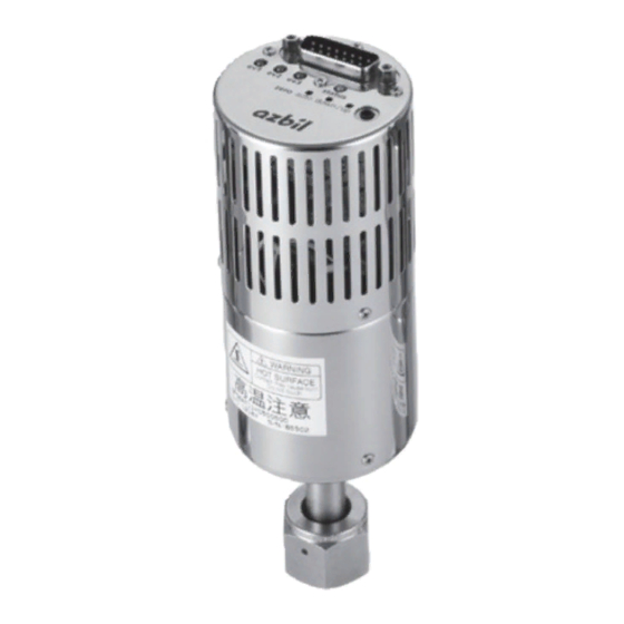
CP-SP-1400E
Sapphire Capacitance Diaphragm Gauge
Model SPG _ _
User's Manual
Thank you for purchasing an Azbil Corporation product.
This manual contains information for ensuring the correct use
of this product. It also provides necessary information for in-
stallation, maintenance, and troubleshooting.
This manual should be read by those who design and main-
tain equipment that uses this product.
Be sure to keep this manual nearby for handy reference.
Please read "Terms and Conditions" from the following URL
before ordering and use.
https://www.azbil.com/products/factory/order.html
NOTICE
Be sure that the user receives this manual before the product
is used.
Copying or duplicating this user's manual in part or in whole is
forbidden. The information and specifications in this manual
are subject to change without notice.
Considerable effort has been made to ensure that this manual
is free from inaccuracies and omissions. If you should find an
error or omission, please contact the azbil Group.
In no event is Azbil Corporation liable to anyone for any
indirect, special or consequential damages as a result of using
this product.
SAFETY PRECAUTIONS
Safety precautions are for ensuring safe and correct use of
this product, and for preventing injury to the operator and
other people or damage to property. You must observe these
safety precautions. Also, be sure to read and understand the
contents of this user's manual.
Key to symbols
l
WARNING
Warnings are indicated when mishandling this prod-
uct might result in death or serious injury to the user.
CAUTION
Cautions are indicated when mishandling this product
might result in minor injury to the user, or only physi-
cal damage to this product.
WARNING
The burst pressure is the pressure at which this device
will break. To avoid an accident, never apply pressure
exceeding the burst pressure.
Do not use this device in explosive atmospheres or
near flammable fluids or steam.
Always use the specified fittings and gaskets. After
the piping work has been completed, check that there
are no gas leaks before operating the device.
The surface of this device is very hot while the power
is ON and for a while after the power has been turned
OFF. To avoid a burn, do not touch it during this pe-
riod. When removing this device, turn the power OFF
and allow sufficient time for it to cool. If there is a
chance that work personnel will come in contact with
this device after installation, take appropriate coun-
termeasures. (Self-heating models)
Use the device within the operating ranges recom-
mended in the specifications (temperature, humidity,
voltage, atmosphere, etc.).
Using it outside these ranges might cause fire or de-
vice failure.
When wiring the power for this device, be sure to in-
stall a master cut-off switch for the electrical power
within easy reach of the operator.
Wire the device properly according to the standards
given in this document, using the specified power
source and installation methods. Not doing so might
result in fire or device failure.
Do not allow wire or solder clippings, water, etc. to
enter the case of this device. They could cause fire or
device failure.
Do not the block ventilation holes. Doing so might
cause fire or device failure.
Use the relays in this device within the operating
ranges recommended in the specifications. Otherwise,
fire or device failure may result. If there is a possibility
that the device will be used in conditions that are out-
side the range of the specifications, take appropriate
countermeasures.
The device is a capacitance diaphragm vacuum gauge that uses a
sapphire capacitance pressure sensor to achieve high accuracy and
reliability, compact size, and light weight. Self-heating and non–self-
heating models are available. On self-heating models, the heating
temperature can be selected. The device is especially suited for use in
semiconductor manufacturing. It features the following:
•
A single-crystal sapphire pressure sensing medium, offering excel-
lent corrosion resistance, ability to withstand high temperatures,
and excellent mechanical characteristics. The capacitive measure-
ment design provides high repeatability even when used in a high-
temperature environment.
•
Small size and light weight, achieved by micromachining technology.
•
Advanced signal processing technology, contributing to excellent
temperature characteristics and linearity of measurement.
•
Microprocessor-based digital PID, providing fast warm-up time
and stable sensor temperature control. (Self-heating models)
•
A wide range of supply power voltages.
•
Easy zero point adjustment with automatic adjustment button or
up/down zero adjustment buttons.
•
Model SLP-SP5 Smart Loader Package (sold separately), for easy
monitoring of the device and setting of its parameters from a PC.
•
Equipped with three event relays. Relay settings can be changed eas-
ily with the Smart Loader Package (model SLP-SP5, sold separately).
•
Conformity to EMC directives; CE-marked; compliance with
EN61326-1 and EN61326-2-3.
For information on the model SLP-SP5 Smart Loader Package,
refer to User's Manual for Smart Loader Package Model SLP-SP5
for Sapphire Capacitance Diaphragm Gauge Model SPG _ _
(CP-UM-5499E).
1
WARNING
CAUTION
OVERVIEW
Advertisement
Table of Contents
Troubleshooting

Subscribe to Our Youtube Channel
Related Manuals for Azbil SPG Series


Summary of Contents for Azbil SPG Series
- Page 1 Group. countermeasures. In no event is Azbil Corporation liable to anyone for any indirect, special or consequential damages as a result of using OVERVIEW this product.
- Page 2 SPG8A SPG8A *IV (pressure range) must be less than 100 Pa. Note: If a model No. combination that is not listed as possible is needed, please contact the azbil Group.
- Page 3 „ „ Part names INSTALLATION D-sub 15-pin connector (male) Set screw (#4-40UNC) WARNING Always use the specified fittings and gaskets. After the Status LED piping work has been completed, check that there are no gas leaks before operating the device. Loader jack ev1 ev2 ev3 status...
- Page 4 • 24 V DC (single power supply) WIRING Power supply (+) WARNING 24 V DC Power supply (COM) Power supply (−) The surface of this device is very hot while the power is ON and for a while after the power has been turned OFF. To avoid Output (+) a burn, do not touch it during this period.
- Page 5 In these cases, th e status LED flashes alternately red and orange Important notice: If you send this device to Azbil Corporation for repair, fill three times out the Safety Sheet on page 8 and include it with the device.
- Page 6 „ „ Troubleshooting Items Specifications Symptom Action Burst pressure* 700 kPa abs Input power Voltage range: ±15 V DC ±10 % (dual power supplies) or Status LED does Check that the wiring is connected correctly. supply 24 V DC ±10 % (single power supply) not light up Allowable ripple voltage: 0.5 Vp-p max.
- Page 7 NW16 tting type If more accurate measurement is required, return the unit to Azbil Corporation for calibration. If the marginal pressure is exceeded, the proper operation of this unit can no longer be guaranteed. In this case, replace the unit with a new one.
- Page 8 IMPORTANT NOTE: If it is necessary to send this device back to Azbil Corporation for repair, photocopy the following Safety Sheet, fill in the required items, and return the sheet with the unit. The Safety Sheet is intended to ensure that the customer’s product is safe for repair personnel and for the environment.
Need help?
Do you have a question about the SPG Series and is the answer not in the manual?
Questions and answers