Table of Contents
Advertisement
Quick Links
No.CP-UM-5800E
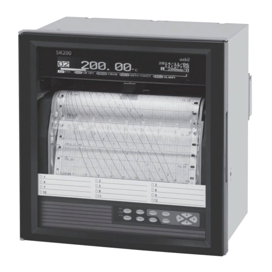
Hybrid Recorder
SR200
(Pen Type)
Instruction Manual
Wiring/Installation
Thank you for purchasing the SR series
Hybrid Recorder.
This manual contains information for
ensuring the correct use of the SR
series Hybrid Recorder. It also provides
necessary information for installation,
maintenance, and troubleshooting.
This manual should be read by those
who design and maintain equipment
that uses the SR series Hybrid
Recorder. Be sure to keep this manual
nearby for handy reference.
Advertisement
Table of Contents

Subscribe to Our Youtube Channel
Related Manuals for Azbil SR Series


Summary of Contents for Azbil SR Series
- Page 1 No.CP-UM-5800E Hybrid Recorder SR200 (Pen Type) Instruction Manual Wiring/Installation Thank you for purchasing the SR series Hybrid Recorder. This manual contains information for ensuring the correct use of the SR series Hybrid Recorder. It also provides necessary information for installation, maintenance, and troubleshooting.
-
Page 2: Table Of Contents
Table of contents 1. Introduction ........................1 2. For Safe Use ........................4 2-1. Preconditions for Use ............................4 2-2. Symbol Mark............................... 4 2-3. Label ................................... 4 2-4. Important Explanation ............................5 3. Model Code List ......................6 4. Mounting and Wiring ..................... 7 4-1. -
Page 3: Introduction
3. Replacement of parts or accessories that have reached the end of their life. Furthermore, the term ‘warranty’ in this sense covers only an Azbil ’s product itself. Therefore, we are not responsible for compensation for whatever the damage that is triggered by failure of our product. - Page 4 Before use Make sure to check the following before use after unpacking the unit. If you have any question, please contact your dealer or our nearest office. 1. Exterior check Check that the appearance of the product has no damage. 2.
- Page 5 4. About attached chart paper For the unit, the chart paper 81407861-001 (1 book) is available and attached. For the case that the chart paper is to be specified, various scales are available as follows. Printed scale Item Item number Remarks (The following numbers are printed.) Folding standard chart...
-
Page 6: For Safe Use
2. For Safe Use If the unit is used in a manner not specified by the manufacturer, the protection provided by the unit may be impaired. For safe use of the unit, please read and understand the following cautions. 2-1. Preconditions for Use The unit is a component type general product to be used mounted on an indoor instrumentation panel. -
Page 7: Important Explanation
2-4. Important Explanation Warning To avoid severe accidents, make sure to read and understand the following. 1. Switch and overcurrent protection device Power/protective This unit is not provided with a replaceable overcurrent conductor terminal protective device. Prepare a switch and an overcurrent protective device for the power supply (circuit breakers, To the protective Overcurrent... -
Page 8: Model Code List
3. Model Code List □□□□□□ SR-2 Input point 01: 1 pen 02: 2 pen 03: 3 pen 04: 4 pen Power A: 100 to 240V AC Communications N: None E: Ethernet R: RS232C A: RS422A/RS485 Q: RS232C + RS485 C: RS422A/RS485 + RS485 G: Ethernet + RS422A/RS485 + RS485 Alarm output + remote contacts 0: None... -
Page 9: Mounting And Wiring
4. Mounting and Wiring 4-1. External Dimensions 241 When alarm output/remote contacts unit and communication unit are added Unit: mm 4-2. Mounting (1) Use the recorder mounting on an indoor installed instrumentation panel. (2) Brackets can be attached to a panel of steel with thickness of 2 to 6mm or equivalent strength. - Page 10 (1) Insert the unit into the panel cutout from the front of the panel. (2) Screw lightly two provided mounting screws into the screw holes on left/right side (two locations in total) of the recorder. (3) Insert the hexagon heads of screws installed above into the round holes of brackets, (from the front) sliding them as shown in the figure, press it firmly against the panel, and tighten them with the provided wrench or a Phillips-head screwdriver.
-
Page 11: Wiring
4-3. Wiring 1. Terminal board diagram The figure below is the diagram of the terminal board with the option [Alarm relay output (12 points ‘a’ contact) + remote contacts (10 points) and communication interface]. - 9 -... - Page 12 The figure below is the diagram of the terminal board with the option [Alarm relay output (8 points ‘c‘ contact) + remote contacts (10 points) and communication interface]. - 10 -...
- Page 13 The figure below is the diagram of the terminal board with the option [Alarm relay output (2 points ‘a ‘contact) and communication interface]. - 11 -...
- Page 14 Alert symbol mark ( ) and location Mark is attached to the location to which if human body touches, an electric shock may be generated. Warning Terminal name Location of attached mark Power terminal Lower left of power terminal Measurement input terminal Upper left of terminal cover Mechanical relay ‘c’...
- Page 15 2. Precautions on wiring Precautions on wiring are described below. Observe them to maintain safety and reliability. Feed power source For the power source for the unit, use the single-phase power source with stable voltage and without waveform strain to prevent malfunctions. (1) Switch and overcurrent protective device Add a switch and overcurrent protective device (250V, 3A) to the feed power source to prevent an electric shock on wiring.
- Page 16 Use crimping terminals. (1) To prevent looseness or disconnection of terminals and short circuit between terminals, install crimping terminals to termination of connection cables. (2) To prevent an electric shock, use crimping terminals with insulation sleeves. Terminal Type and Termination Treatment Terminal board Termination treatment (Unit: mm) Diameter...
- Page 17 3. Power/protective conductor terminals wiring Power/protective conductor terminals Power terminal Protective conductor terminal 100 - 240V AC 50/60Hz 40 VA MAX Power (voltage, frequency, and power consumption) Turn OFF feed power source. Warning Before power/protective conductor terminals wiring, make sure to turn off the feed power source to prevent an electric shock.
- Page 18 4. Measurement input terminals wiring Caution Allowable input voltage Measurement input terminal Turn OFF the feed power source before wiring Input type Allowable input voltage Voltage, thermocouple input ±10VDC * to prevent an electric shock. Resistance thermometer input ±6VDC Install crimping terminals with insulation *±60VDC for channels specified with ±10V range or more sleeves to input terminals for wiring.
- Page 19 Input unit terminal cover mounting/removing (1) Raise the cover to the direction of the arrow. (2) Turn to the direction of the arrow. (3) Pull it out to the direction of the arrow to remove. 5. Alarm output terminals wiring (option) Alarm output terminals The terminal configuration depends on the output specification.
- Page 20 Wiring Turn OFF the feed power source and the power source for buffer relay before wiring to prevent an electric shock. (1) Wire the cable to the load via the buffer relay. (2) To the alarm output terminals, type O crimp style terminal with insulation sleeve which is connected to double insulated signal wire should be connected.
- Page 21 Precautions on wiring The following are precautions on wiring. Item Description Mechanical relay output (Minimum load) Power supply Resistance load Inductive load specification contact 100μA 100mVDC 100VAC capacity 240VAC (Common to ‘a’ contact and 30VDC ‘c’ contact) Contact protective element ...
- Page 22 No voltage contact Warning For contacts connected to the remote contacts terminals, use switches or relays driven with voltage level 30VAC or 60VDC or less or manual contacts which support light load. Reference Remote contact Remote contact enabled operation name ...
- Page 23 ON: Short-circuit OFF: Open Operation for which terminal No. is decided automatically Operation name Terminal contact signal 3 chart speed setting other than the setting here is required. (See general 8-7. Chart Speed Settings.) Recording ON/OFF and 3 chart Between COM and EX terminals speed selection (1) 3 chart speed selection...
- Page 24 7. Communication I/F terminal wiring (partly option) SR can be connected for communications with RS232C, RS422A, RS485, and Ethernet. terminals Communications terminal Ethernet connector Communications terminal type (option) RS232C RS422A COM1 Short with Short with RS485 COM2 RS485 * RS232C and RS422A/485 of COM1 are to be specified on purchase. Communications cables Please prepare communication cables before wiring in advance.
- Page 25 (2) RS422A Connection between a line converter and the unit Crimp type ring terminals ↔ Crimp type ring terminals RS422A cable Cable (for a line converter) (black) (black) (white) (white) (red) (red) (green) (green) Shape (blue) (blue) Line converter side Recorder side 4-core cable of twisted 2-core cables of twisted VCTF lines.
- Page 26 (3) RS485 Connection between the unit and other devices and between a line converter and the unit Cable Crimp type ring terminals ↔ Crimp type ring terminals RS485 cable (black)SA RDA(black) (white)SB RDB(white) (green)SG SG(green) Shape Device side, Line converter side Recorder side 2-core cable of twisted CVVS lines.
- Page 27 (2) RS422A wiring PC and multiple devices are connected with RS422A. A line converter is required. RS422A cable is within 1.2km of total extension and up to 31 devices can be connected. Install a resistor of 100Ω to the last edge of the transmission line device side. (General metal film resistors will be fine.
- Page 28 (4) Ethernet wiring Example of connection between PC and Ethernet devices (one-to-one connection) Crossover twist-pair cable with shield (Max.100m) PC side Device side Example of connection between PC and HUB/Ethernet devices (one-to-N connection) Straight twist-pair cable PC side with shield (Max.100m) Straight twist-pair cable with shield (Max.100m)
-
Page 29: Part Names
5. Part Names 5-1. Front Section of Internal Unit Power switch Open the display board same direction as the unit door. The power switch is located at the upper left of the unit. Display Enlarged view of power switch SD card Engineering port Operation/set keys slot... -
Page 30: Operation/Set Keys
5-2. Operation/Set Keys Status LED Lights in green while recording is ON. Recording is turned ON/OFF by the key. Flashes when chart ends. CARD Lights in green when SD card is recognized by the unit, or flashes in a recognition process. ... -
Page 31: Operation
6. Operation Note Handling of chart cassette 6-1. Preparation for Operation Be careful of injury by dropping the chart cassette after pulling it from inner unit. Take care not to catch your fingers in the unit when putting the chart cassette back. 1. - Page 32 2. How to set plotter pen and cartridge pen 1. Recording pen types Plotter pen Cartridge pen (1) There are two types of recording pens, the plotter pens for digital printing and cartridge pen for trace printing. (2) There are four kinds of cartridge pens for the 1 pen to the 4 pen.
- Page 33 4. Setting plotter pen 5. Setting cartridge pen Penholder Main Shaft Penholder Plotter pen (1) Insert the plotter pen into the penholder untill it Setting is completed stops. (Note) Incomplete insertion may result in recording (1) Push the arms of the cartridge pen into the troubles.
-
Page 34: Basic Operation
6-2. Basic Operation 1. Power on Turn the power switch to ON while the chart cassette is in the housing. Data will be shown on the display after about 10 seconds. After detecting the initial position, the printer prints the date and time and then feeds chart about 5mm. Note 1 Display backup While recording is OFF... - Page 35 3. Chart recording operation “*** Quit recording? ***” Recording ON Pressing the key turns recording OFF. “*** Start Digital data printing? ***” Press the key to start. “*** Start recording? ***” Recording OFF Pressing the key turns recording ON. Any of the above settings can be cancelled by pressing the key.
- Page 36 Data printing Print numeric values of the latest measurement data as shown in the example below. Printing mode is different depending on the chart speed. When the chart speed is 1 to 499mm/H, trace printing is continued without interruption. Printing is done by synchronized with chart feeding.
- Page 37 Chart feed Chart can be fed using the key. While the key is pressed, chart is fed at a speed of 600mm/min. When fast-feeding chart, recording is stopped. Feed chart when a measurement target or measurement condition is changed. Reference Feeding chart Chart can be fed manually using the drum.
-
Page 38: Inspection And Maintenance
7. Inspection and Maintenance 7-1. Routine Inspection Check the remaining amount of chart and recording condition on a daily basis to keep the unit in good condition. When any abnormality is found, take an appropriate action according to the “general 11. Troubleshooting”. Maintenance/inspection item Operation When the trace printing (trend line) fade away or becomes less visible, replace the... -
Page 39: Battery Removal Method For The Purpose Of Disposa
7-3. Battery removal method for the purpose of disposa Do not replace the battery. Doing so might cause damage or malfunction. Caution Do not remove the battery except when disposing the recorder. 1. Removing the battery Removing the internal chassis (1) Open the unit door and then open the display board in the same direction. - Page 40 Removing the battery (1) The battery is located at the back of the chassis front unit. Battery (2) Using a tapered, insulated tool, remove the battery from the battery holder. (1) The unit components include a small amount of harmful chemical substance no more than the defined amount by RoHS.
- Page 41 Revision History of CP-UM-5800E Printed Edn. Revised pages Description Dec. 2014 4. Change the lengths of the chart paper of ”Remarks” 2), (2) Change 16 pages → 4-3. Wiring, 2. Precautions on wiring June 2017 4), (8) Change the sentences Change AAS-511A-014-04 to AAS-511A-014-06...
- Page 42 1. Warranty period and warranty scope 1.1 Warranty period Azbil Corporation's products shall be warranted for one (1) year from the date of your purchase of the said products or the delivery of the said products to a place designated by you.
- Page 43 Azbil Corporation's products every 5 to 10 years unless otherwise specified in specifications or instruction manuals.
- Page 44 [Selling agency] [Manufacturer] CHINO Corporation 1st edition: Dec. 2014 (K ) 32-8 KUMANO-CHO, ITABASHI-KU, 2nd edition: June 2017 (K ) TOKYO 173-8632 JAPAN...
Need help?
Do you have a question about the SR Series and is the answer not in the manual?
Questions and answers