
Related Manuals for Sices GC250


Summary of Contents for Sices GC250
- Page 1 Technical Manual GC250 File name: EAAM057608EN.docx Rev. 08 Date: 23/05/2019 ID Document: EAAM0576 Product: GC250...
- Page 2 Modified Par. 5.2.1 and 5.2.2 Modified Par. 5.4.1; Modified Par. 5.4.2 23/05/2019 Modified paragraphs 5.8, 5.6.4, 5.6.3, 5.8.4, 7.4.8.2, 9.1, 10.5, 10.7.48 Added paragraphs 5.8.3, 7.4.8.12 e 7.4.8.13 24/10/2019 Modified paragraphs 5.6.4, 7.4.7.9, 7.4.8.3, 7.4.8.9, 9.2.3 GC250 Technical Manual EAAM057608EN...
-
Page 3: Table Of Contents
T.22..T.28 Connection to the mains ..............48 5.9.1 Measurement of the mains neutral ............... 48 5.10 T.30..T.36 Connection to generator .............. 49 5.10.1 Measurement of the generator neutral ............ 49 5.11 T.28..T.40 Current transformer connection........... 50 EAAM057608EN GC250 Technical Manual... - Page 4 6 USB Connection ......................51 CAN-BUS connections ..................52 7 Command and indications ..................53 Front panel GC250 ..................... 53 Push-buttons ...................... 54 Indicators ......................55 Multifunctional display ..................56 7.4.1 LCD lighting ....................56 7.4.2 Contrast adjustment ..................56 7.4.3 Mode navigation ...................
- Page 5 38 – Starter battery voltage, high ................120 39 – Service required ..................... 121 41 – Minimum oil pressure (from contact) .............. 121 42 – Minimum oil pressure (from analogue sensor) ..........122 43 – Low oil pressure (from contact) ..............122 EAAM057608EN GC250 Technical Manual...
- Page 6 Service hours counter ................138 11.6 Counters ..................... 138 11.6.1 Counters reset ..................139 11.7 Clock ......................140 11.7.1 Engine TEST start-up weekly planning..........140 11.7.2 Weekly scheduling of engine operating time intervals......140 GC250 Technical Manual EAAM057608EN...
- Page 7 11.8 Non-volatile memory .................. 141 11.9 Plant name ....................142 11.10 Power saving mode ..................142 11.11 CAN-BUS connection with engines ............143 EAAM057608EN GC250 Technical Manual...
- Page 8 DOF.3152 30; 33; 105; 107 DIF.3302 46; 134 DOF.3153 33 DIF.4001 44; 46; 108 DOF.4001 33; 107 DIF.4003 46; 108 DOF.4003 33; 107 DIF.4004 46; 108 DOF.4004 33; 107 DIF.4011 46; 108 DOF.4005 33; 107 viii GC250 Technical Manual EAAM057608EN...
- Page 9 EVT.1079 72 P.0250 90 EVT.2000 72 P.0271 99 EVT.4000 72 P.0301 92; 93; 110 EVT.5000 72 P.0302 93; 110 P.0303 92; 93; 110 P.0304 93; 110 P.0000 64; 67; 81; 82 P.0305 91; 92; 110; 111 EAAM057608EN GC250 Technical Manual...
- Page 10 P.0395 126 P.2152 44 P.0396 126 P.3000 32 P.0397 127 P.3001 26; 97; 127; 135 P.0398 127 P.3002 26 P.0400 132 P.4001 29 P.0401 133; 134 P.4003 109 P.0402 133 P.4004 109 P.0403 133 P.4005 109 GC250 Technical Manual EAAM057608EN...
- Page 11 ST_329 37 ST_036 36 ST_330 37 ST_038 36 ST_331 37 ST_039 36 ST_332 37 ST_040 36 ST_333 37 ST_041 36 ST_334 37 ST_064 36 ST_335 37 ST_065 36 ST_998 37 ST_068 36 ST_999 37 ST_069 36 EAAM057608EN GC250 Technical Manual...
-
Page 12: Introduction
[1] SICES EAAM0448xx GC250 parameters chart. [2] SICES EAAM0458xx - BoardPRG3.xx Manual. [3] SICES EAAS0449xx GC250 parameters chart. [4] SICES EAAM0136xx – J1939 Interface Manual. [5] CANopen – Cabling and Connector Pin Assignment – CiA Draft Recommendation DR- 303-1 [6] BOSCH CAN Specification – Version 2.0 – 1991, Robert Bosch Gmbh. -
Page 13: Introduction And Prerequisites
The devices are supplied with a generic “default” configuration; it is at the installer’s care to adjust the operating parameters to the specific application. SICES srl carries out a great effort to improve and update its products; therefore, they are subject to both hardware and software modifications without notice. Some of the features described in this manual may therefore differ from those present in your device. -
Page 14: Conventions
Several parts of this manual refer to the controller's software revisions. These revisions are marked with the assigned SICES code (shown on the rear panel of the controller). The format of the code is: EB0250256XXYY, where “XX” is the main version and “YY” is the minor version. -
Page 15: Views Of The Device
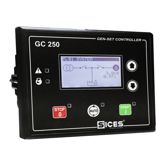
GC250 Front view Back GC250 EAAM057608EN GC250 Technical Manual... -
Page 16: Technical Features
Amperometric transformers must provide at least one REPEATED (DOUBLE) insulation for the use of the device in the Overvoltage Cat. III. Required connection of the return poles of the amperometric transformers (T.41) to the negative power supply of the device. GC250 Technical Manual EAAM057608EN... - Page 17 T.09 terminal as analogue input to acquire voltage measurements from 0 to 32V or as additional digital input with +Vbatt activation. The voltage measurement acquired is displayed in the page S.07 of the display. EAAM057608EN GC250 Technical Manual...
-
Page 18: Measurement Resolution
CANBUS Connection USB 2.0 for non permanent connection to PC (max 6m) only for the configuration of parameters with program SICES BoardPrg3. The device is directly supplied by PC and turns on in OFF/RESET mode when it is connected, with maximum consumption of 250mA from USB port. -
Page 19: Installation
520Vac. The maximum voltage related to the protective earthing is 300 Vac. The device can operate in CAT.III only if the supply minus terminal of the device and the neutral terminal of the generator are connected to the protective earth. EAAM057608EN GC250 Technical Manual... -
Page 20: In/Out Connections And Configuration
Digital input 2 T.18 Digital input 3 T.19 Digital input 4 T.20 CAN_H CANBUS connection and ECU engine T.21 CAN_L T.22 T.24 4 poles x2.5mm Mains voltages 2 screw terminal T.26 T.28 T.30 Genset voltages 4 poles x2.5mm GC250 Technical Manual EAAM057608EN... -
Page 21: Correspondence Input/Output And Their Logic Functions
T.16 DI_CONTROLLER_T16 N.U. Available T.17 DI_CONTROLLER_T17 N.U. Available T.18 DI_CONTROLLER_T18 EMERGENCY STOP EMERGENCY STOP T.19 DI_CONTROLLER_T19 START INHIBITION START INHIBITION T.09 DI_CONTROLLER_T09 N.U. Available T.13 DI_CONTROLLER_T13 N.U. Available T.14 DI_CONTROLLER_T14 N.U. Available T.15 DI_CONTROLLER_T15 N.U. Available EAAM057608EN GC250 Technical Manual... -
Page 22: Plant Type
The selection is done through parameter P.0802 P.0802 = 1 for SSB plants (default configuration) P.0802 = 0 SPM plants. According to the plant type, the principle connection diagram changes, as indicated in the following paragraphs. GC250 Technical Manual EAAM057608EN... -
Page 23: Principle Connection Diagram Ssb Plant
5.2.1 Principle connection diagram SSB plant EAAM057608EN GC250 Technical Manual... -
Page 24: Principle Connection Diagram Spm Plant
5.2.2 Principle connection diagram SPM plant GC250 Technical Manual EAAM057608EN... -
Page 25: And T.02 Device Supply
12 or 24V for managing the related logics and alarms. acknowledgement is carried out every time you switch to the mode. OFF/RESET WARNING! : when installing, connect the battery positive only after opening all fuses available in the panel. EAAM057608EN GC250 Technical Manual... -
Page 26: Engine Commands Outputs T.03 And T.04
CAN-BUS interface), it can be reconfigured to serve other purposes by means of the parameter P.3002, refer to par. 5.6.2 and [1]. There are two different ways to stop the engine: Drop-down stop system GC250 Technical Manual EAAM057608EN... - Page 27 NO between battery plus and valve/stop command with no intermediate fuses which, when activated, delivers positive voltage to the stop valve by bypassing the controller command. EAAM057608EN GC250 Technical Manual...
-
Page 28: D+ Energizing And Checking The Operation Of The Recharge Alternator
Using parameters P.0230 and P.0231 it is possible to enable/disable the acknowledgement of engine started by D+ signal; by using the parameter P.0349 it is possible to disable the AL.005 anomaly(“A005 – Broken belt”) (see document [1]). GC250 Technical Manual EAAM057608EN... -
Page 29: D+ Input Used As Analogue Input
The outputs functions configured by default are the following: EAAM057608EN GC250 Technical Manual... -
Page 30: Load Switching Commands Ssb Plants
KA and KB in battery voltage coils cabled as per the diagram. In case you use contactors directly operating in battery voltage coil, it is possible to command them directly from the static outputs of the device, inverting the polarity of GC250 Technical Manual EAAM057608EN... -
Page 31: Load Switching Commands Spm Plants
P.0219. The default configuration of the device provides a use of the output T.08 that is specifically configured as default. It is by the way possible to use any digital output configured with the function. EAAM057608EN GC250 Technical Manual... -
Page 32: Digital Outputs Configuration
P.3000 =12 (that is 4+8). By default, all bits are set to zero. The digital outputs can be used directly as command for devices outside the controller, or for reporting certain operating conditions. Functions configurable on the digital outputs GC250 Technical Manual EAAM057608EN... - Page 33 DOF.4005 Alarms, deactivations It is activated in the presence of alarms, deactivations and unloads. and unloads. DOF.4031 Generator faults. It is activated in the presence of faults of the generator, i.e.: ▪ 001: Minimum generator voltage. EAAM057608EN GC250 Technical Manual...
- Page 34 ▪ 134: Maximum temperature of the coolant from the Can-Bus. ▪ 135: Minimum level of the coolant from Can-Bus. ▪ 136: Low level of the coolant from Can-Bus. ▪ 137: Low battery voltage from Can-Bus. ▪ 142: Minimum oil pressure from Can-Bus. GC250 Technical Manual EAAM057608EN...
-
Page 35: And/Or Logics
OR (it is enough that at least one condition is verified). It is not possible to have mixed logics AND/OR (it is possible using the virtual digital inputs, see afterwards). EAAM057608EN GC250 Technical Manual... - Page 36 ST_070 GCB under voltage coil command ST_071 Impulse open command for GCB ST_072 Impulse closing command for GCB ST_073 MCB under voltage coil command ST_074 Impulse open command for MCB ST_075 Impulse closing command for MCB GC250 Technical Manual EAAM057608EN...
- Page 37 Status 13 from engine management by file ST_333 Status 14 from engine management by file ST_334 Status 15 from engine management by file ST_335 Status 16 from engine management by file ST_998 Always active ST_999 Always not active EAAM057608EN GC250 Technical Manual...
-
Page 38: Analogue Inputs
ATTENTION!: we recommend in any case to observe the functions provided for each single resistive input, according to the connection diagram above, that is with: T.13 Fuel level input (FL Fuel Level) T.14 oil pressure input (OP Oil Pressure). T.15 Coolant Temperature (CT Coolant Temperature) GC250 Technical Manual EAAM057608EN... -
Page 39: Configuration And Functions Of Analogue Inputs
As for the measures concerning the engine (pressure, temperature) with engine having digital control unit, normally those data are directly acquired directly via CAN-BUS; sometimes it may be necessary the use and the configuration of the resistive level sensor. EAAM057608EN GC250 Technical Manual... - Page 40 Bit 8. If this bit is “ON”, the controller activates a fault only if the engine is activated. Bit 9. If this is a bit “ON”, the controller activates a fault only if the time of covering the alarm of low oil pressure has passed. GC250 Technical Manual EAAM057608EN...
- Page 41 50 °C 195 Ohm 100 °C 38 Ohm 150 °C 10 Ohm Pressure sensor VDO (AIF.1000) 0 bar 10 Ohm 10 bar 180 Ohm VDO Level Sensors (AIF.1200, AIF.1210, AIF.1220) 180 Ohm 100 % 10 Ohm EAAM057608EN GC250 Technical Manual...
-
Page 42: Conversion Curves
BoardPrg3. The virtual inputs can be configured as feature and can be used the same way as the physical inputs. GC250 Technical Manual EAAM057608EN... -
Page 43: Digital Inputs
4.5VDC (around 4.15VDC for input T.16). Avoid situations where intermediate or undefined voltage levels can occur. If you don’t use the same signal shared among different devices beside GC250, it is recommendable the use of series diodes at the inputs as per the following figure:... -
Page 44: Virtual Digital Inputs
The parameter that configures the delay for an input is used by the controller only for some input functions. The following chart highlights when it is used: INFORMATION!: in BoardPrg3, the boxes for the delay is always displayed, even if is not used by the controller. GC250 Technical Manual EAAM057608EN... - Page 45 When the input becomes"active", parameters of alternative configuration set 1 are copied in the working configuration. DIF.2152 Select configuration 2. When the input becomes"active", parameters of alternative configuration set 2 are copied in the working configuration. EAAM057608EN GC250 Technical Manual...
- Page 46 When the input is “active”, if the time set by means of the DIF.4013 De-activation (after oil delay). P.0216 parameter from engine start has elapsed, a deactivation command is issued: the message shown is the one set by means of the related parameters. GC250 Technical Manual EAAM057608EN...
- Page 47 (language-dependant) warning is activated. When the input is “active”, if the time set by means of the DIF.4232 Maximum coolant temperature P.0216 parameter from engine start has elapsed, a fixed description (language-dependant) warning is activated. EAAM057608EN GC250 Technical Manual...
-
Page 48: Measurement Of The Mains Neutral
If the system is configured with the neutral connection, the neutral voltage is measured in relation with GND. The values of the V1-N, V2-N and V3-N phase voltages and the VN voltage of the neutral in relation to GND for the mains are displayed on page M.03. GC250 Technical Manual EAAM057608EN... -
Page 49: Measurement Of The Generator Neutral
The values of the V1-N, V2-N and V3-N phase voltages and the VN voltage of the neutral in relation to GND for the mains are displayed on page M.05. If the device is configured not to measure the neutral voltage, then page M.05 will not be displayed. EAAM057608EN GC250 Technical Manual... - Page 50 Connect to terminal T.40 a terminal of the CT connected on phase L3. Connect to terminal T.41 the returns of all three CTs. For single phase connection, terminals T.39 and T.40 should not be connected. GC250 Technical Manual EAAM057608EN...
-
Page 51: Usb Connection
The P.0107 sets the current values of the CTs primary. GC250 has a USB port with B-type connector for a temporary connection with a PC for the parameters configuration or for the download of history logs. The USB protocol specifications do not allow it to be used permanently in the industrial sector due to limited length of the cable and to the relatively elevated sensitivity to electrical disturbances including on the PC side. -
Page 52: Can-Bus Connections
[6]. For features and operation details, as well as for the configuration of the CAN-BUS communication parameters, see documents [4], [5] e [6]. The CAN-BUS interface of the GC250 is not galvanically isolated. Connections: Connect terminal T.20 to terminal CAN_H of the engine's control unit. -
Page 53: Command And Indications
Fig. 1 – GC250 Front Panel 1 - Push-button 2 - Indicators The controls consist of 5 buttons (1a, 1b). The front panel also has 5 luminous indicators (2a, 2b). EAAM057608EN GC250 Technical Manual... - Page 54 When the controller is turned on, keeping it pressed at the same time as the STOP button, it allows access to the special functions. GC250 Technical Manual EAAM057608EN...
- Page 55 The Gen-set control module is in another operating mode. Indicates the presence of at least one lockout, one deactivation or power-off ALARM There is at least one active warning. No anomalies. Indicates engine running ENGINE RUNNING Indicates engine idle EAAM057608EN GC250 Technical Manual...
-
Page 56: Multifunctional Display
STATUS Status information S.XX MEASURES Electrical measurements M.XX ENGINE Engine measurements E.XX HISTORY History logs H.XX Normally, the mode navigation is carried out by keeping pressed for at least one second the buttons UP and DOWN GC250 Technical Manual EAAM057608EN... -
Page 57: Structure Of Display Areas
7.4.4 Structure of display areas E.01 AUTO KEY: 1 - Status bar 2 - Data area °C Fig. 4 - Display areas 7.4.5 Top status bar The top status bar contains information on navigation, times and/or some status information. EAAM057608EN GC250 Technical Manual... -
Page 58: Status Information (S.xx)
: glow plug preheating : engine start. : delay of starting attempts. : delay of first supply. : engine running. : engine cooling. : stopping cycle The status of the electrical mains (absent, low, high etc.) GC250 Technical Manual EAAM057608EN... - Page 59 In order to see the others, it is required to: ▼. Press and keep press the button Use the ▲▼ push-buttons to scroll the anomalies. At the end Press and keep press the button ▲. EAAM057608EN GC250 Technical Manual...
- Page 60 To reset the maximum values (and at the same time force the exit from the BUS-OFF status) it is necessary to: Keep button ▼ pressed: the counters will be highlighted. Press and hold the ▲ e ▼ buttons for five seconds. GC250 Technical Manual EAAM057608EN...
-
Page 61: Electrical Measures (M.xx)
INFORMATION! If an external mains sensor is used (see par. 9.2.2) the symbol flashes or is fix according to the status of the external sensor, while the below measures are always those of the internal sensor of the device. EAAM057608EN GC250 Technical Manual... - Page 62 To the bottom right there is an icon that allows immediate identification of the fact that the page is related to the MAINS measures. 7.4.7.4 M.04 GENERATOR This page shows the Phase-to-Phase concatenated voltages and the frequency of the generator, in addition to the rotation direction of the phases (clockwise or counter clockwise). GC250 Technical Manual EAAM057608EN...
- Page 63 Press and hold button ▲ to deselect the counter. Attention: from version 01.08, if a password has been configured in parameter P.0001 ("user" protection level), it will not be possible to reset the counters until this password is entered EAAM057608EN GC250 Technical Manual...
-
Page 64: Engine Measurements (E.xx)
Attention: from version 01.08, if a password has been configured in parameter P.0001 ("user" protection level), it will not be possible to reset the counters until this password is entered (login) in parameter P.0000 (" Access code"). GC250 Technical Manual EAAM057608EN... - Page 65 Air pressure in aspiration duct (ref. SAE J1939: SPN102). Air temperature in the aspiration duct (ref. SAE J1939: SPN105). Intercooler temperature (ref. SAE J1939: SPN52). Pressure in engine basement (ref. SAE J1939: SPN101). Actuator position (ref. SAE J1939: SPN51). EAAM057608EN GC250 Technical Manual...
- Page 66 Not available measures are shown with dashes. If no information is available, the page is not shown. This page shows the following measures Nominal power (KW) Rated speed (rpm) MTU error code Average consumption resettable counter (litres/h) GC250 Technical Manual EAAM057608EN...
- Page 67 3721: “DPF Time Since Last Active Regeneration”. ▪ spn 3242: “DPF Intake Gas Temperature”. ▪ spn 3246: “DPF Outlet Gas Temperature”. ▪ spn 3251: “DPF Differential Pressure”. DOC: ▪ spn 4765: “DOC Intake Gas Temperature”. ▪ spn 4766: “DOC Outlet Gas Temperature”. EAAM057608EN GC250 Technical Manual...
- Page 68 ECU could apply a reduction in engine performance (derating). It is not flashing. Indicates a low level of the Diesel Exhaust Fluid (DEF) tank. It could ▪ Fixed: level below normal. ▪ Flashing: level below normal, derating in progress. GC250 Technical Manual EAAM057608EN...
- Page 69 Some ECUs, to perform the "active" regeneration of the particulate filter, must necessarily increase the engine speed. For this reason, they require consent from the controller before activating this process. The controller sends the consent to the "active" regeneration if the GCB circuit breaker is open. EAAM057608EN GC250 Technical Manual...
-
Page 70: History Logs (H.xx)
When in a mode limiting the use of vertical scroll buttons you may require to press repeatedly button▲. When the procedure starts, the menu is shown with different archive functions. 7.4.9.1 Log selection H.03 AUTO 1/04 GC250 Technical Manual EAAM057608EN... - Page 71 Mains in tolerance EVT.1013 1.00 Inhibition activated (from configurable input) EVT.1014 1.00 Inhibition not activated (from configurable input) EVT.1020 1.00 Generator failure EVT.1021 1.00 Generator on EVT.1022 1.00 Generator in tolerance EVT.1030 1.00 GCB Close command EAAM057608EN GC250 Technical Manual...
- Page 72 EVT.4000: if they are deactivations. EVT.5000: if they are interlocks. When displayed, the value 2000, 3000 , 4000 or 5000 is removed and replaced by the letter “W”, “D” or “A” before the alarm code. GC250 Technical Manual EAAM057608EN...
- Page 73 Mains phase-to-phase voltages and frequency. Generator frequency and phase-to-phase voltages. Generator currents. Active, reactive and apparent powers, the power factor and the type of plant total load. EAAM057608EN GC250 Technical Manual...
- Page 74 7.4.9.5 Slow analogues logs( The slow analogues are recorded at a pace configurable by means of the parameter P.0443 (interval in minutes) and the default interval is 30 minutes. This archive have can store up to GC250 Technical Manual EAAM057608EN...
- Page 75 (in the example, code “6.6” in the engine technical manual will describe the oil low pressure problem). EAAM057608EN GC250 Technical Manual...
- Page 76 To reset an archive to zero, it is necessary to display it first and then to keep the digits ▲ and ▼ for 5 seconds, until when the controller shows a message of reset to zero. GC250 Technical Manual EAAM057608EN...
-
Page 77: Parameters Programming
[1] where they’re described in detail. ATTENTION! S ome functions or particular configurations can be settable or modifiable only through the PC program SICES Board Programmer3. The use of BoardPrg3 is recommended as it simplify a lot the programming operations. -
Page 78: Menu Selection
Entering the programming mode of each single parameter, page of fig. 1 is shown. Each programming parameter (Ref. 3) has a 4-digit numeric code (e.g. P.0125) to identify the variables regardless of the language used. The current value of the parameter is displayed below the description Ref.4. GC250 Technical Manual EAAM057608EN... -
Page 79: Parameters Selection
ASCII chart or to the one that follows/precedes it by ten positions, if also pressed AUTO), while buttons STOP and START allow to select the character to be modified. You can set the ASCII characters from 32 (Space) to EAAM057608EN GC250 Technical Manual... -
Page 80: Set Up Limits
OOFF/RESETmode, access programming, and then press and hold ▲ e ▼. Reload of factory values will be confirmed by a message on the display. Factory values are reloaded only for parameters for which you are granted access rights. GC250 Technical Manual EAAM057608EN... -
Page 81: Protection Password
On the contrary, if you know the “manufacturer” password, it will be in any case possible to cancel or modify the other passwords. In case you lose the “manufacturer password” it is necessary to contact SICES service centre. The following examples show all combinations of passwords assignation. -
Page 82: Password For Commands From Serial Port (Usb)
USB with modbus protocol. To send commands via modbus to the device, it is necessary that each command is preceded by the password contained in P.0004. The default password is “123”. GC250 Technical Manual EAAM057608EN... -
Page 83: Operation Sequence
If there are multiple active inputs at the same time, priority is given to the input that forces OFF/RESET mode, followed by the one that forces MAN mode and finally the mode. one that forces AUTO. EAAM057608EN GC250 Technical Manual... - Page 84 “21” to go back to AUTO. mode. When a digital input, properly set with code 2031 “Test mode request” is activated, the when the same input is controller shifts to TEST and returns to AUTO deactivated. GC250 Technical Manual EAAM057608EN...
-
Page 85: Recording Of Mode In Event Archive
DOF.3005 - “Remote Start”. The controller activates this output when in REMOTE START mode. DOF.3011 - “Not in OFF/RESET”. The controller activates this output when it is in AUTO or AUTO o MAN mode. EAAM057608EN GC250 Technical Manual... -
Page 86: Operation Modes And Logics And/Or
P.0201: hysteresis applied to all the thresholds related to mains voltage and frequency. It is a percentage value related to P.0116 and to P.0105. P.0203: low mains voltages threshold (percentage respect to P.0116); under this value mains is considered anomalous. GC250 Technical Manual EAAM057608EN... - Page 87 Downwards to the maximum frequency threshold (i.e., between 53.75 Hz and 55.00 Hz). These values define the following bands: 0.00 Band A: low 45.00 Band B: hysteresis 46.25 (45.00 + 1.25) Band C: in tolerance 53.75 (55.00 + 1.25) Band D: hysteresis 55.00 EAAM057608EN GC250 Technical Manual...
- Page 88 “E” band and now it is in “D” band, it is considered however “In tolerance”. On the other hand, if it was in “C” band and now is in “D” band, it is considered “Low”. GC250 Technical Manual EAAM057608EN...
-
Page 89: External Mains Sensor
To use the external sensor and deactivate the internal one, it is necessary to put the rated mains voltage P.0116 to zero. EAAM057608EN GC250 Technical Manual... -
Page 90: Mains Global Status
No generator supplying the loads and bit 1 of P.0250 is “1”: the duration of the “mains presence delay” is set by parameter P.0205. No generator supplying the loads and bit 1 of P.0250 is “0”: the duration of the “mains presence delay” is 0 seconds. GC250 Technical Manual EAAM057608EN... -
Page 91: Communication And Events
Let us see a practical example upon how thresholds work, with default values for the parameters we have seen. Parameter Description Default value Frequency (Hz) P.0105 Rated frequency 50 Hz P.0228 Stopped engine threshold due 10.0 % to frequency EAAM057608EN GC250 Technical Manual... -
Page 92: Genset Voltages
P.0303: high generator voltage threshold (percentage of P.0102); over this value the generator cannot be connected to the loads. Let us see a practical example upon how thresholds work, with default values for the parameters we have seen. GC250 Technical Manual EAAM057608EN... -
Page 93: Generator Status
9.3.3 Generator status. For general management purposes, generator can be in three conditions: EAAM057608EN GC250 Technical Manual... -
Page 94: Communication And Events
AUTO otherwise the delay is null. Use parameter P.0208 to set a delay between input's physical de-activation and this function's logic de-activation: in case the generator is already running, the delay is two seconds (firm). GC250 Technical Manual EAAM057608EN... -
Page 95: Inhibition From Clock
P.0231 has to be major than P.0230 (otherwise this check is disabled). The instantaneous status of the engine is: Idle if the D+ voltage is lower than P.0230. In movement if the D+ voltage is higher than P.0230, but lower than P.0231. EAAM057608EN GC250 Technical Manual... -
Page 96: Engine Commands
The controller can handle the following different commands for engine management: START: command for the starter. FUEL: command for the fuel solenoid valve. STOP: stop command when energized. PREHEAT: command for Diesel engines glow-plugs preheating. GC250 Technical Manual EAAM057608EN... -
Page 97: Command Sequence Of The Engine
In AUTO mode, the device automatically starts the engine and possibly with more than one attempt; the maximum duration of the single starting attempt is selected with parameter P.0210, the number of attempts with parameter P.0211. EAAM057608EN GC250 Technical Manual... - Page 98 P.0217 (“Maximum time for full speed conditions”): the controller activates the failure AL.008 (“A008 – Failed full speed conditions”). In this status only command FUEL is active. In this status only command RUNNING is active. GC250 Technical Manual EAAM057608EN...
- Page 99 From the cooling status it is possible to go back to the in running status if the stop requests cease and there is at least one starting request (for example, we were in this status following EAAM057608EN GC250 Technical Manual...
-
Page 100: Communication And Events
The controller records any change of the start/stop requests in the events log, if it is enabled with bit 6 of the P.0441parameter: EVT.1050: Manual start-up command EVT.1051: Manual stop command EVT.1052: Auto start command EVT.1053: Auto stop command GC250 Technical Manual EAAM057608EN... -
Page 101: Circuit Breakers Management
(guaranteeing that the possible function DOF.2001 is active from at least 0.5 seconds): the output remains active even with open circuit breaker. The controller disables this output to close the circuit breaker: the output remains EAAM057608EN GC250 Technical Manual... -
Page 102: Acquiring Breakers Status
9.6.4 Switching logic in AUTO mode After detecting the mains failure condition, the controller starts the engine. After detecting the engine running and with parameters of generator frequency and voltage in the respective GC250 Technical Manual EAAM057608EN... -
Page 103: Man Or Test Management Logic
It is possible to manage the breakers using Modbus commands via USB. To send the commands you need to write in sequence (within 5 seconds): ▪ HOLDING REGISTER 101: write the password configured with the parameter P.0004. EAAM057608EN GC250 Technical Manual... -
Page 104: Automatic Power Delivery Of The Generator Inhibited
EVT.1036: MCB open command EVT.1037: MCB closed. EVT.1038: MCB open. The board makes controls and status of the switches available, for AND/OR logics, through the following internal statuses: ST.064 - "GCB status" GC250 Technical Manual EAAM057608EN... -
Page 105: Anomalies
DOF.3152 – “Outside siren”. The output is controlled together with the inside beeper; the purpose is that of using a more powerful beeper or a lamp. EAAM057608EN GC250 Technical Manual... -
Page 106: Silencing The Horn
By using a command from the serial port. The commands can be protected by a password (P.0004) which has to be sent before any command, and can be deactivated GC250 Technical Manual EAAM057608EN... -
Page 107: Acknowledging Anomaly
DOF.4032: the output will be activated if at least an anomaly linked to the engine is active. DOF.4034: the output will be activated if at least an anomaly linked to the fuel is active. EAAM057608EN GC250 Technical Manual... -
Page 108: Anomalies Connected To Digital Inputs
P.0216 (“engine protection masking time”). The board will activate this anomaly if the digital input is uninterruptedly active for the configured (P.2002) time span. GC250 Technical Manual EAAM057608EN... -
Page 109: Anomalies Connected To Analogue Inputs
From this point on, words enabling and activation will be utilized: Enabling an anomaly means having the minimum conditions necessary in order for the controller to observe the cause. Activation of an anomaly refers to the cause after enabling. EAAM057608EN GC250 Technical Manual... -
Page 110: Minimum Generator Voltage
It is enabled the first time (from engine start) the generator's frequency and voltages enter the tolerance range (see generator sequence description). In MAN it is only enabled if the GCB GC250 Technical Manual EAAM057608EN... -
Page 111: Maximum Generator Frequency
The controller realises a depending on time protection in current (which therefore intervenes as quickly as the current is in overload). The used curve is named EXTREMELY INVERSE, and implements an I t. It is a generator protection as it limits the thermal accumulation of the EAAM057608EN GC250 Technical Manual... - Page 112 The following graph shows the curve used for enabling protection, with a value of P.0310 set to 60 seconds (I is the maximum current): GC250 Technical Manual EAAM057608EN...
-
Page 113: Manual Stop While In Auto
It is activated when the generator voltages and frequency are not steady within tolerance range within time P.0217 from the engine running acknowledgement (or from the end of the engine’s idle cycle, if enabled). EAAM057608EN GC250 Technical Manual... -
Page 114: Mains Circuit Breaker (Mcb) Not Closed
Protection is given by setting a threshold (P.0311) expressed as a percentage of the system rated current (see maximum current protection to calculate rated current with parameters P.0101, P.0102 and P.0106). It is only enabled if the controller has been started GC250 Technical Manual EAAM057608EN... -
Page 115: Overspeed
Related parameters: P.0211 Numbers of starting attempts To disable: Enabled in: AUTO, TEST, REMOTE START This protection is always enabled. It activates if the controller has performed P.0211 consecutive engine start attempts (auto start) without success (engine running). EAAM057608EN GC250 Technical Manual... -
Page 116: Mains Circuit Breaker (Mcb) Not Open
MAN, AUTO, TEST, REMOTE START This protection is enabled only when one of the digital inputs of the controller is configured to acquire the minimum fuel level contact of the float (feature DIF.4211 - “Minimum fuel level” in GC250 Technical Manual EAAM057608EN... -
Page 117: Minimum Fuel Level (From Analogue Sensor)
It is enabled only when the controller is configured to use the analogue fuel level sensor (P.4009 suitably configured), or if said sensor is physically connected to the device terminal. It activates if the level measure remains continuously below or equal to threshold P.0345 (in percentage) for time P.0346. EAAM057608EN GC250 Technical Manual... -
Page 118: High Fuel Level (From Contact)
It activates if the input configured is continuously “active” for the time configured, but only after the time P.0216 (oil mask) from engine start has elapsed (this is to allow you to start the engine idle, to cool it off) GC250 Technical Manual EAAM057608EN... -
Page 119: High Coolant Temperature (From Analogue Sensor)
Related parameters: P.4025 Function for analogue input T.15 (CT) or equivalent parameter for other inputs P.0216 Time for engine protection mask P.0337 Threshold for maximum cooling temperature P.0338 Delay for maximum cooling temperature P.0700 Engine type EAAM057608EN GC250 Technical Manual... -
Page 120: Maximum Oil Temperature (From Analogue Sensor)
17V, it considers to be powered by a 12V battery, otherwise it will consider a 24 V rated voltage. Starter battery voltage, high Icon: Type: Warning GC250 Technical Manual EAAM057608EN... -
Page 121: Service Required
(parameter P.2002 or equivalent). It is only enabled if the controller has been started by the controller (if the command for the fuel solenoid is activated) and is disabled in the engine start/stop phases. It activates if the input configured is continuously “active” for the EAAM057608EN GC250 Technical Manual... -
Page 122: Minimum Oil Pressure (From Analogue Sensor)
Low oil pressure (from analogue sensor) Icon: Type: Warning Category: Engine protection Related parameters: P.4017 Function for analogue input T.14 (OP) or equivalent parameter for other inputs P.0216 Time for engine protection mask P.0339 Threshold for low oil pressure GC250 Technical Manual EAAM057608EN... -
Page 123: Emergency Stop
It activates if the system total active power is positive and remains continuously over the threshold P.0350 for time P.0351. With parameter P.0352 it is possible to select the protection to be activated (warning, deactivation, alarm). EAAM057608EN GC250 Technical Manual... -
Page 124: Generator Voltages Unbalance
High oil temperature (from analogue sensor) Icon: Type: Warning Category: Engine protection Related parameters: P.4025 Function for analogue input T.15 (CT) or equivalent parameter for other inputs P.0216 Time for engine protection mask P.0373 Threshold for high oil temperature GC250 Technical Manual EAAM057608EN... -
Page 125: Wrong Phases Sequence
Threshold P.0391 is expressed as a percentage of the system rated voltage (phase voltage). The protection activates when at least one of the generator voltages continuously lower than the threshold P.0391 for time P.0392. EAAM057608EN GC250 Technical Manual... -
Page 126: Clock Not Valid
In addition, the generator voltages and frequency must be within the tolerance range and the load must be changed-overt to the generator. Threshold P.0393 is expressed as a percentage GC250 Technical Manual EAAM057608EN... -
Page 127: High Generator Frequency
P.0404. It activates if the pump operates continuously for the time set, but the issuance of a warning does not change the pump's operating mode (it turns off the pump, which restarts as soon as the warning is acknowledged). EAAM057608EN GC250 Technical Manual... -
Page 128: Low Coolant Temperature (From Analogue Sensor)
This protection is enabled only if the board is connected to the engine via the CAN BUS (P.0700 different from zero). It is activated when the engine signals the battery-charger alternator failure status over the CAN BUS. Maximum speed from CAN-BUS Icon: GC250 Technical Manual EAAM057608EN... -
Page 129: High Coolant Temperature From Can-Bus
Minimum coolant level from CAN-BUS. Icon: Type: Alarm Category: Engine protection Related parameters: P.0700 Engine type P.0704 Anomalies deactivation mask from Can-Bus To disable: bit 7 of P.0704 on Enabled in: MAN, AUTO, TEST, REMOTE START EAAM057608EN GC250 Technical Manual... -
Page 130: Low Coolant Level From Can Bus
This protection is enabled only if the board is connected to the engine via the CAN BUS (P.0700 different from zero). It is activated when the engine signals the minimum oil pressure state over the CAN BUS. Low oil pressure from CAN BUS Icon: Type: Warning Category: Engine protection GC250 Technical Manual EAAM057608EN... -
Page 131: High Oil Temperature From Can Bus
This protection is enabled only if the board is connected to the engine via the CAN BUS (P.0700 different from zero). It is activated when the engine signals the water in fuel state over the CAN BUS. EAAM057608EN GC250 Technical Manual... -
Page 132: Warnings Cumulative Yellow Lamp From Can-Bus
Confirm keeping button▼pressed or cancel the modification pressing and holding ▲. INFORMATION! : the fuel pump control mode is a normal parameter (P.0400) of the controller, therefore it can be modified including from the programming windows. The following modes are available: GC250 Technical Manual EAAM057608EN... -
Page 133: Use With An Analogue Level Transducer To Use This Function
(for disabling anomalies). Very important is the thresholds setting which should be ranked by level (from down up), as follows: minimum, low, start, stop, high. As already explained, the controller operates even if thresholds are not EAAM057608EN GC250 Technical Manual... -
Page 134: To Use This Function Requires
Basically, if you want to reverse the logic of an output you need to add the corresponding value into its parameter: Activates if the level is “start”, “low” or “minimum”. Deactivates if the level is ”stop” or “maximum”. Retains the actual command if in “hysteresis”. GC250 Technical Manual EAAM057608EN... -
Page 135: Manual Pump Control
In the same way, the output is disabled if the power rises above the upper threshold for the set time. These thresholds and delays are set with following parameters: EAAM057608EN GC250 Technical Manual... -
Page 136: High Load
It is possible to change the configuration by means the following input digital functions: DIF.2151 – “Select configuration 1”. When the input becomes "active", parameters of alternative configuration set 1 are copied in the working configuration. GC250 Technical Manual EAAM057608EN... -
Page 137: Ejp Function
A signal will activate 30 minutes before B, it will require to set 1500 seconds, i.e. 25 minutes (it is possible to set delays up to 4000 seconds, i.e. 66 minutes). Configure a second digital input with feature DIF.2502 – “Loading inhibition) (in parameter P.2004 or the equivalents). EAAM057608EN GC250 Technical Manual... -
Page 138: Maintenance
The controller manages internally the following counters: 1. Partial active power meter (kWh) (resettable), with power measured when the loads are connected to the generator; it measures only the supplied power and does not measure in case of power reverse. GC250 Technical Manual EAAM057608EN... -
Page 139: Counters Reset
The resetting procedure is common for all the counters, but it only applies to some of them, based on the page displayed on the multifunctional display. See in paragraph 7.4.8.3 the description of the display page that contains the counter to be reset to zero. EAAM057608EN GC250 Technical Manual... -
Page 140: Clock
The planning is made on a weekly basis: therefore, it is possible to plan in which days the generator must operate. Besides days, it is possible to set a single auto operation enable time slot common to all selected days. GC250 Technical Manual EAAM057608EN... - Page 141 2 (0002) Different information (lcd display contrast, maintenance request). 1.00 4 (0004) Counters 1.00 8 (0008) History log for diagnose codes acquired via CAN-BUS from the engine. 1.00 16 (0010) Reserved. 1.00 32 (0020) Parameters alternative configurations. 1.00 64 (0040) Parameter: EAAM057608EN GC250 Technical Manual...
- Page 142 • “3-Both edges”: on digital input activation and deactivation. The deactivation of the energy saving mode with relative date and time is recorded in the event store, if enabled by the bit 0 of parameter P.0441. GC250 Technical Manual EAAM057608EN...
- Page 143 P.0703 on “0”, GC250 doesn't transmit anything on the CAN-BUS. In the end it is possible to set a time-limit through P.0711 parameter: GC250 will activate an anomaly in case it doesn't receive messages from the ECU of the engine within this period of time.
- Page 145 All rights reserved. SICES s.r.l. reserves the right to modify this document without prior notice. SICES has made any effort to ensure that the information herein provide are correct; in any case SICES does not assume any liability for the use this information.
Need help?
Do you have a question about the GC250 and is the answer not in the manual?
Questions and answers