Sices GC315 Series User Manual
Hide thumbs
Also See for GC315 Series:
- Technical manual (214 pages) ,
- User and installation manual (9 pages)

Related Manuals for Sices GC315 Series


Summary of Contents for Sices GC315 Series
- Page 1 Plus Link Mains Link Mains+Link Filename: EAAM045503EN.docx Rev. 04 Date: 04/09/2015 ID Document: Product: GC315xx-GC400xx...
- Page 2 INDEX 1 Safety information ......................3 2 Information concerning disposal ................3 3 Forward ......................... 4 4 Definitions ........................4 5 Main functions ......................5 Plus Link Front Panel GC315, GC315 and GC315 ............ 5 Link Front Panel GC400, GC400 ................
- Page 3 The manual must always be kept in a safe place where it is readily available for quick reference. The manual should be read carefully, and every paragraph understood by the operators and technicians doing routine and periodic maintenance. If the manual is lost or damaged, ask the installer/manufacturer for a copy, quoting the model, code, serial number and year of manufacture.
- Page 4 Mains Mains+Link GC400 and GC400 Throughout this document, GC315x will refer to all controllers of the GC315 series and Plus GC400x will refer to all controllers of the GC400 series, while the names GC315, GC315 Plus GC400, etc. will refer to a specific controller and the names GC315/GC315...
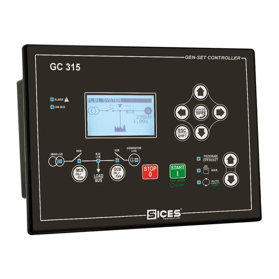
- Page 5 Plus Link Plus Link KEY GC315/GC315 /GC315 1 - Buttons 2 - Indicators The controls consist of 12 buttons (1a, 1b, 1c, 1d, 1e, 1f). The front panel also has some luminous indicators (2a, 2b, 2c). User’s Manual GC315xx-GC400xx...
- Page 6 Link Link Link KEY GC400/GC400 1 - Buttons 2 - Indicators The controls consist of 12 buttons (1a, 1b, 1c, 1d, 1e, 1f). The front panel also has some luminous indicators (2a, 2b, 2c). User’s Manual GC315xx-GC400xx...
- Page 7 Mains Mains+Link Mains Mains+Link Link Mains Mains+ KEY GC400 /GC400 1 - Buttons 2 - Indicators The controls consist of 12 buttons (1a, 1b, 1c, 1d, 1e, 1f). The front panel also has some luminous indicators (2a, 2b, 2c). User’s Manual GC315xx-GC400xx...
- Page 8 Pushbutton Function The genset is disabled; all anomaly signals are disabled. All possible alarms OFF/RESET are reset. You can program the parameters. PROGRAM The Gen-set control module is set for manual gen-set control. Press the START button to start the engine. Press the STOP button to stop the engine.
- Page 9 Pushbutton Function By pressing the START button it is possible to activate/deactivate the TEST mode. If there are no other specific configurations, it does not switch the load from Mains to Genset and vice versa. WARNING! The STOP button, causes the stop of the Generator if running and the activation of a lockout unless configured otherwise.
- Page 10 Pushbutton Function In the PROGRAM menu, you can enter the programming mode and open a submenu, change a variable or parameter, and confirm the operation. In the LOG menu, you can activate the HISTORY LOG function and open the selected log, “acknowledge” any EEPROM errors at power-up. Upon the occurrence of an alarm or lockout, the pressing of the button ENTER/ACK recognizes the presence of an error and turns off the siren.
- Page 11 Pushbutton Function In MAN mode it can be used to start the engine. The button can be configured in two ways: Fully manual (the starter motor is engaged all the time the button is pressed or until the engine running is detected). Fully automatic (simply press and release the “START”...
- Page 12 Signalling Function Ref. 2c Different operation mode. Indicates the presence of at least one lockout or power-off. Signals at least one warning which has not yet been ALARM acknowledged with the “ACK/ENTER” button. Ref. 2a No lockouts or warnings. Signals that the CAN-BUS interface is active and in ERROR- ...
- Page 13 Signalling Function Signals BUS line ON. Signals BUS line OFF. Flashing at 50% if the BUS line voltage is outside tolerance range. BUSLIVE Ref. 2b GC400x Flashing at 50% - During synchronization phase (opposite sequence to GCB). ...
- Page 14 The display has different display modes with various pages. Mode Description Page identifier PROGRAMMING Programming P.XX STATUS Status information S.XX MEASURES Electrical measurements M.XX ENGINE Engine measurements E.XX Parallel functions B.XX GC400PMCB HISTORY History logs H.XX Generally, navigation between modes takes place via buttons DOWN Ref.
- Page 15 E.01 ENGINE KEY: 1 - Status bar Oil Press. (bar): 2 - Data area Coolant Temp. (°C): Fig. 3 - Display areas The top status bar contains information on navigation, times and/or some status information. KEY: 1a - Mode identifier E.02 ENGINE 1b - Page identifier 1c - Page title...
- Page 16 Access to the parameters programming mode can be controlled by 3 different PASSWORD levels, which are listed in order of priority. 1. SICES password GC400x 2. Manufacturer password 3. Installer password 4.
- Page 17 The INSTALLER can change the User Password and the Installer Password. The MANUFACTURER can display and change all three passwords. SICES can display and change some critical parameters for configuring the plant parallel function. Warning: The critical parameters must not be changed by the user.
- Page 18 Some parameters require the setting or modification of the alphanumeric strings. In this case, pressing ACK/ENTER makes the square brackets [...] around the variable flash, and a cursor appears under the first character of the string. Using the LEFT and RIGHT buttons, you can select which character to change.
- Page 19 The S.06(GC315x)/S.03(GC400x) (CONTROLLER) page displays the specific information of the Gen-set: language set, date/time, serial number (ID code), firmware revision. Only for GC400x: the necessary internal code to have a temporary SICES level password. The pages S.07-08-09(GC315x)/S.08-09-10(GC400x) (GENERIC STATUS) display the general status of the digital inputs.
- Page 20 and the display priority of the same in the pages are pre-assigned when configuring the system parameters. The page S.10(GC315x)/E.11(GC400x) (FUEL PUMP) (available only if the fuel pump management output is configured) contains information and commands related to the fuel pumps.
- Page 21 It displays the status of all protections of parallel with the mains. The disabled protections are not displayed. For each protection enabled, the controller displays a text (for example “27<<”: it is displayed in reverse if the protection is enabled - mains out of tolerance).
- Page 22 M.11 (AUX MEASURES) Page displays the additional information on genset voltages and currents, used for the protection of the 27Q mains parallel. M.12 (REGULATIONS) (GC400x) Page displays genset and mains/bus voltages and frequencies at the same time. It displays the parameters used to monitor the parallel operation. This windows allows you to change the power supplied in the mains parallel applications in BASE LOAD and IMPORT/EXPORT operation (par.
- Page 23 The page E.13(GC315x)/E.14 (GC400x) (MAINTENANCE) displays the counters related to the Genset maintenance. In this mode, measures and statuses connected to CANBus PMCBus are displayed. The page B.01 (MC100/BTB100) displays, for diagnostic purposes, the mains controllers (MC100) and tie breaker controllers (BTB100) connected to the PMCBus. The pages B.02, B.03, B.04 (GENSETS) (GC400x) display the information related to the PMC-Bus mains (PMC-Bus address, active and reactive power) up to 7 gensets.
- Page 24 LOAD GENERATOR MAINS ENGINE ELECTRONIC CONTROL DEVICE Plus GC315, GC315 ELECTRICAL PANEL In this mode the Load is usually powered by the Mains with the MCB contactor closed. The supply of the Load is guaranteed all the time the MCB remains closed because it is fed by the same Mains. If a Black out occurs on the Mains, the Load will remain de-energized and the gen-set idle.
- Page 25 3) Press the “GCB” switching button and check that the “GCB” and “BUS LIVE” lights are The Load is now powered by the Generator. When the Mains returns after the Black out and/or the restoration of the fault, “MAINS LIVE” light ON, switching of the Load to Mains can be performed. It is the operator decision to keep the power supply from the Generator.
- Page 26 WARNING! Switching between MCB and GCB or vice versa, creates a blackout on the Load line. The Load will remain de-energized for the set time necessary to ensure a correct switching of the contactors. 2) The generating set keeps running for the cooling phase of the engine (phase for the disposal of excessive heat).
- Page 27 : The operating sequence described above is generic and in some cases may INFORMATION! not correspond to the one implemented in your system. For further information, please contact your installer/Manufacturer. User’s Manual GC315xx-GC400xx...
- Page 28 The GC400x devices can be configured to manage several types of plant and the use modes can vary consequently For example, please find below some basic operations of a SSB+SSTP plant (Single Stand-By + Single Short Time Parallel) and a MPM plant (Multiple Parallel to Mains). Mains Mains+Link LOAD...
- Page 29 With Genset off, the MCB contactor is commanded to open after pressing the “MCB” button for at least 5 seconds. The Load stays disconnected. The engine must be started by the operator by pressing START. With the Genset parameters and Mains live and with controller configured to manage the synchronisation on the GCB contactor pressing the “GCB”, the synchronisation is activated.
- Page 30 : The operating sequence described above is generic and in some cases may INFORMATION! not correspond to the one implemented in your system. For further information, please contact your installer/Manufacturer. The sole purpose of the “TEST” sequence is that of testing the Generator set in order to check the operating condition in preparation for a possible emergency situation (e.g.
- Page 31 This type of plant considers the presence of more gensets in parallel among them in island mode and to supply the Load. The normal operation is AUTO mode and considers all gensets not in OFF/RESET or MAN on, in parallel among them and in power sharing. The power supplied by the single genset is defined by a parameter or an external potentiometer.
- Page 32 To select a language different from that set, view the screen S.06 (GEN-SET) using the navigation buttons. To change the LANGUAGE press ACK/ENTER : the square brackets [ ] will start flashing. Use the UP and DOWN buttons to display the available LANGUAGES, then press ACK/ENTER to confirm or Esc/SHIFT to cancel the changes.
- Page 33 Gen-set implements the full management of the fuel pump, to pump fuel from the storage tank to the The pump can be managed automatically or manually using the tank on the generator. controls on the front panel. Select function With MODE UP Ref.1a and MODE DOWN Ref.1a buttons, select the MAN, AUTO or TEST navigation buttons, select the “STATUS (S.xx) Status...
- Page 34 SICES s.r.l. reserves the right to modify this document without prior notice. SICES has made any effort to ensure that the information herein provide are correct; in any case SICES does not assume any liability for the use these information.
Need help?
Do you have a question about the GC315 Series and is the answer not in the manual?
Questions and answers