Advertisement
Quick Links
Advertisement

Related Manuals for Sices RN200


Summary of Contents for Sices RN200
- Page 1 File name: EAAM072500EN.docx Rev. 00 Date: 03/08/2020 ID Document: EAAM72500 Product: RN200...
- Page 2 7.3.2 Inverter ......................28 Most important parameters ................. 29 7.4.1 Minimum power for generators ..............29 7.4.2 Spinning reserve for generators ..............29 8 Special setting ......................31 Selecting the language ..................31 Date/time setting ....................31 RN200 user manual...
- Page 3 Proper recycling and disposal helps to preserve nature and prevent harmful effects on health and the environment. This manual describes the RN200 controller. BLOCK: it is used to indicate an anomaly that makes it impossible to use renewable sources, and causes the inverters to automatically switch off.
- Page 4 RNCB: circuit breaker that connects a group of renewable sources to the common bars. MGCB: circuit breaker that connects the common bars to the loads. CANBUS: communication interface used by all SICES controllers for the exchange of information between them.
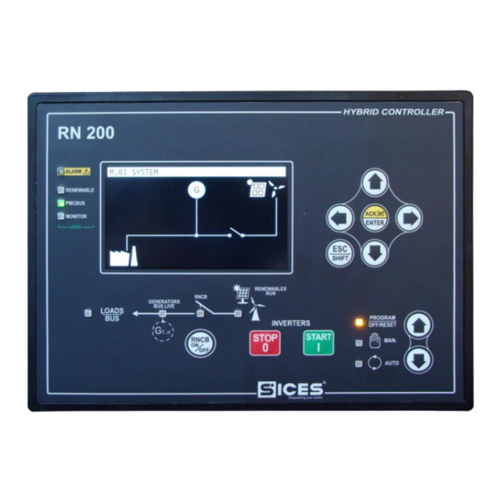
- Page 5 Press the RNCB button to open/close the RNCB circuit breaker. The controller is ready for the automatic management of the inverters for the AUTO renewable sources, which will be started when the conditions of the system (Automatic) allow/require it. MODE DOWN RN200 user manual 3...
- Page 6 (or the selected character) of a unit (if pressed with the ESC/SHIFT button, the value is modified by 10 units). • While viewing the parameter menus or the historical archive, they allow you to go to the previous/next item. RN200 user manual...
- Page 7 When the controller is turned on: STOP • Allows to repeat the test of the non-volatile memory if there are errors. • Ignores any pending firmware update. • Holding it together with the START button allows access to special functions. RN200 user manual 5...
- Page 8 There are no anomalies. Indicates that at least one external device (inverter) is communicating correctly with RN200. Indicates that no external device (inverter) is communicating correctly with RN200. Indicates that the Can Bus interface is active, functioning and in ...
- Page 9 At least one inverter is running. Flashing 25% on: no inverter running in the presence of a start command. Flashing 75% on: at least one inverter running in the presence of a stop command. RN200 user manual 7...
- Page 10 ▲ and ▼ buttons. In the event that the ▲ and ▼ buttons are to be used to manage specific functions within a page, the ACK/ENTER buttons are required to activate these functions, the ESC/SHIFT buttons to deactivate them. RN200 user manual...
- Page 11 By activating bit 6 of parameter P.0495. If there are status messages that contain a waiting time (countdown), the controller always displays these messages instead of the title; in case of page change (user manual navigation), the title of the new page RN200 user manual 9...
- Page 12 RN200 user manual...
- Page 13 (for example "<400>"), it means that you do not have the rights to modify the parameter. This may depend on: • The device is not in OFF/RESET mode. In fact, most of the parameters can only be changed in this mode. RN200 user manual 11...
- Page 14 USER level. Each level also allows you to change your password and the passwords of the lower levels. The SICES protection level also allows you to view and modify some critical system configuration parameters. This password is not configurable, but is supplied together with the controller.
- Page 15 The first column identifies the type of parameter used (input / output). • The second column identifies the resource associated to the parameter. The resources are normally shown with SICES codification (e.g. the digital input 1 is RN200 user manual 13...
- Page 16 (nicknames) to the resources. It is possible to view the symbols in the second column, in place of SICES codes: press ACK/ENTER (as to select a different PLC block) and press ◄►; confirm with ACK/ENTER button. See the PLC documentation for the description of the SICES codes for the identification of the PLC resources.
- Page 17 ACK/ENTER button, select a language with the ▲ and ▼ buttons and confirm with the ACK/ENTER button. Note: RN200 is provided as standard only with the languages ENGLISH, ITALIAN. With the BoardPrg3 program it is possible to transfer other languages to the controller.
- Page 18 The number of active "outgoing" TCP connections (Modbus TCP master to inverter). Some of these values can be set with the controller parameters, or acquired dynamically by the DHCP server. This page displays the status of the Can Bus interfaces. RN200 has two interfaces. For each interface are displayed: ...
- Page 19 ACK/ENTER key and use the ▲ and ▼ keys. Internally, RN200 uses a third CAN interface for communication between its microcontrollers. If necessary, the status of the third interface can also be displayed by activating bit 8 of parameter P.0495.
- Page 20 If more than 8 functions are used for the analogue RN200 user manual...
- Page 21 The controller displays the three L-L voltages, the frequency, the phases sequence and the neutral-B- voltage. By pressing the ACK/ENTER button, the L-N voltages are displayed instead of the L-L voltages (press ACK/ENTER again to return to the L-L) RN200 user manual 19...
- Page 22 (login) in parameter P.0000 ("access code"). These pages are dedicated to displaying the measurements acquired by the analogue inputs configured as a "generic sensor". The operator has the right to acquire measures that are in RN200 user manual...
- Page 23 If some measures are not available, they are displayed with dashes. The upper part contains the total information (sum of all inverters). This information is always present, even if the communication with the inverters is set in BROADCAST mode. It contains: RN200 user manual 21...
- Page 24 (i.e. it is producing the maximum possible, which, based on the environmental conditions, it is lower than the set point). So, the dashes indicate that no reactive power limitation is active on the inverter. RN200 user manual...
- Page 25 In this mode, the measurements and states acquired by the Can Bus PMCB, which connects all the SICES controllers, are displayed in a complete way. This page shows the list of the controllers recognized on the Can Bus PMCB. It is useful for diagnostic purposes.
- Page 26 RN controller is limiting the active power production of its inverters. The imported or exported reactive power (kvar and %). The measurement is followed by a "*" f the RN controller is limiting the reactive power production of its inverters. RN200 user manual...
- Page 27 ACK/ENTER and ESC/SHIFT buttons simultaneously for five seconds. Attention: the operation is irreversible, a deleted archive cannot be recovered. Press the ESC/SHIFT button to return to the list of archives or to exit the historical archives view. RN200 user manual 25...
- Page 28 RN200 is able to exchange data with the inverters for the renewable sources, using the Modbus protocol. This is a binding limit: the inverter must implement this protocol. RN200 can acquire the following measurements from inverters: Manufacturer, model, options.
- Page 29 Commands through the communication ports (two separate commands are provided for closing and opening). Note: in MAN RN200 it will never automatically close the switch; however, it can open it, because its protections are also active in this operating mode.
- Page 30 Commands through the communication ports (two separate commands are provided for starting and stopping). Note: in MAN RN200 it will never automatically start the inverters; however, it can stop them, because its protections are also active in this operating mode.
- Page 31 If the conditions are verified, the controller commands the start-up of the inverters as soon as the operator presses the START button. In order to keep the generators efficient and reduce periodic maintenance, RN200 is able to limit the power supplied by the inverters (if needed), to keep the generators at an adequate power level.
- Page 32 The choice of value for these parameters should be the consequence of a long-term observation of the production of renewable sources in the plant. Only in this way is it possible to find the lowest possible value that still keeps the system safe. RN200 user manual...
- Page 33 “PROGRAM → 4 AUXILIARY FUNCTIONS → 4.7 Device → 4.7.1 Date- Time”. The controller provides 6 parameters that allow you to change the year, month, day of the month, hours, minutes and seconds respectively. Follow the instructions contained in chapter 6.5.1 to modify the parameters. RN200 user manual 31...
- Page 35 All rights reserved. SICES s.r.l. reserves the right to modify this document without prior notice. SICES has made any effort to ensure that the information herein provide are correct; in any case SICES does not assume any liability for the use these information.
Need help?
Do you have a question about the RN200 and is the answer not in the manual?
Questions and answers