Advertisement
Quick Links
Advertisement

Subscribe to Our Youtube Channel
Related Manuals for Sices DST4601/PX


Summary of Contents for Sices DST4601/PX
- Page 1 Filename: EAAM019704EN.docx Rev. 04 Date: 08/05/2013 ID Document: EAAM0197 Product: DST4601/PX...
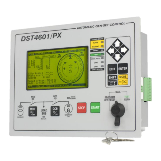
- Page 2 Definitions ........................ 3 Front Panel ....................... 3 Selector (ref. to fig. 1) ................... 4 Pushbuttons (ref. to fig. 1) ..................5 Indicators (ref. to fig. 1) ..................7 Multifunctional display ................... 8 2.4.1 Mode navigation (ref. to fig. 2) ................ 9 2.4.2 Display area layout (ref.
- Page 3 NOTE: Read this manual carefully before operating the device. (EN) LOCKOUT - is used to indicate a fault that prevents the generator from operating and causes automatic and immediate emergency engine shutoff. POWER-OFF - is used to indicate a fault that prevents the generator from operating and causes the standard automatic engine shutoff (including a cooling phase).
- Page 4 Selector Function position The generator is disabled; warnings and lockouts are cancelled. OFF/RESET You can program the parameters. PROGRAM Gen-set is in manual mode. Press the START button to start the engine. Press the STOP button to stop the engine. button and GCB button for the manual control of the commutation/switches in accordance with system SW - HW configuration.
- Page 5 Pushbuttons Function Dead key. If this is pressed with another button, it changes the button function. When the page displays HELP, holding this button down displays the HELPmessage on the bottom status bar. SHIFT Horizontal scrolling buttons. These buttons let you select the previous or next page on the display in all modes, except in the PROGRAM and HISTORY LOGS mode.
- Page 6 Pushbuttons Function Used to command the Mains Circuit Breaker (MCB) or the changeover. The actual function depends also on the plant configuration. Used to acknowledge any kind of alarm and to silence the horn. Pressed at the same time as the START button, it lets you enable/disable the TEST mode.
- Page 7 LED OFF LED steady ON LED flashing Signalling Function Signals at least one lockout or deactivation or unload anomaly. Signals at least one lockout or deactivation which has not yet been ALARM acknowledged with the “MODE/ACK” button ...
- Page 8 Signalling Function Mains power is OFF or MAINS SIMULATION digital input is disabled. Mains power is ON and stable in the range of tolerance, or MAINS SIMULATION digital input is enabled from the set time. MAINS LIVE Flashes at 50% during transition between the previous two states.
- Page 9 The display has different display modes with various pages Mode Page identifier Programming P.XX Status information S.XX Electrical measurements M.XX Engine measurements E.XX PMCB B.XX History logs H.XX Generally, the UP and DOWN buttons are used to navigate between the modes. Fig.
- Page 10 03/04/06 18:23 E.01 ENGINE KEY: 1 - Status bar Press.(Bar) Temp.(°C) Level(%) 2 - Data area xx.x –xxx.x xx.x 3 - Bottom status Oil: xx.x –xxx.x xx.x Coolant: xx.x –xxx.x xx.x Fuel: Actual Requested Lost xxx xxx.x xxx Torque (%): xxxx xx.x Speed (rpm):...
- Page 11 Access to the programming mode can be controlled by 4 different PASSWORD levels, which are listed in order of priority. 1. SICES password 2. Manufacturer password 3. Installer password 4. User password...
- Page 12 The INSTALLER can change the User Password and the Installer Password. The MANUFACTURER can change all three passwords. SICES can display and change some critical parameters for configuring the plant, for parallel function. Warning: The critical parameters must not be changed by the user.
- Page 13 For some parameters you will have to set a value for the string data. In this case, pressing ENTER makes the square brackets [ ] around the variable flash, and a cursor appears under the first character of the string. Using the LEFT and RIGHT buttons, you can select which character to change.
- Page 14 Communication error counters display. If the cause of the malfunction has been removed, in this page you can force exit from the BUS-OFF mode by holding down the MODE EXIT buttons. - engine diagnostic codes, according to the SAE J1939 standard or MTU specifications. In the case of the J1939 standard, when a signal is present the SPN and FMI fault's codes, the number of occurrences (OC), a specific diagnostic code of the family of engines (DTC), and an explanatory text are displayed.
- Page 15 Page B.01 reports status information related to the PMCB network. This includes the number of network devices, the operating mode of the load function, the identifier of the pilot generator and the list of priorities. Page B.02 shows the measurements concerning the generation of energy by the single generators and all the generators in the PMCB network.
- Page 16 To adjust the engine speed and/or voltage manually, press the ENTER button and the MODE button to select speed and voltage regulation; use the UP and DOWN buttons to change the percentage value (%). When the synchroscope indicates the circuit breaker can be closed, press the circuit breaker button again (MCB or GCB ) and hold it down until...
- Page 17 Gen-set can display messages in various languages. To select another language, turn the lockable selector to OFF/RESET, and when you power up Gen-set press the STOP and START buttons simultaneously until the following message appears on the display: Special Function Function [RESERVED] Press the ENTER button, use the UP...
- Page 18 MANUAL-OFF (pump off) Press the ENTER button to confirm the selection. Note: The second option (MANUAL-ON) can be inhibited by Gen-set, in relation to the fuel level (the pump will not start when the tank is full). With the lockable selector in position MAN, AUTO or TEST, from any page or mode, you can open page “S.04 fuel pump page”...
- Page 19 This document is owned by SICES s.r.l.. All rights reserved. SICES s.r.l. reserves the right to modify this document without prior notice. SICES has made any effort to ensure that the information herein provide are correct; in any case SICES does not assume any liability for the use these information.
Need help?
Do you have a question about the DST4601/PX and is the answer not in the manual?
Questions and answers