Advertisement
Quick Links
Advertisement

Related Manuals for Sices HS 315


Summary of Contents for Sices HS 315
- Page 1 File name: EAAM058607EN.docx Rev. 07 Date: 25/09/2019 ID Document: EAAM0586 Product: HS315...
- Page 2 Date Revision Pages Notes 22/03/2017 The first version of the manual, drawn-up for version 01.00 of the controller. 30/08/2017 Valid from version 01.01 of the controller. 1.1, 2, 3, 3.1, 5, 5.4.5, 5.5.5, 5.6.6, 5.7.3, 5.14, 5.14.2, 5.14.3, 5.15, 7.4.3, 7.5.2, 7.5.3.1, 7.5.3.2, 7.5.4.1, 7.5.4.14, 7.5.4.15, 8.2.2, 8.3.6, 8.5.2, 8.5.3, 8.5.4, 8.5.5, 8.5.7, 8.5.7.1, 8.5.7.2, 8.5.7.3, 8.5.9, 8.5.11, 8.5.12, 9.1, 9.2, 9.56, 9.59, 9.213, 9.226, 9.227, 9.228, 9.237, 9.900,...
- Page 3 Introduction ......................1 Reference documents ................... 1 Introduction and prerequisites ................1 Switch SW1 ......................2 Notes on the configuration of the device parameters..........2 Definitions ......................2 ......................3 Terms and Abbreviations ..................3 Software revisions ....................3 Maintenance and cleaning ..................3 1.10 Information concerning disposal ..............
- Page 4 5.7.3 Configuration of analogue outputs ..............43 Optional additional modules ................45 Conversion curves ....................45 5.10 Measurement of the engine rotational speed (PICK-UP or W) JM-5, JM-6 and JM-7 47 5.10.1 Magnetic pick-up ..................47 5.10.2 W signal ....................48 5.11 Connection of the AC voltages of the auxiliary source .........
- Page 5 8.5.1 Programming (P.XX) ..................79 8.5.2 PLC (L.XX) ....................85 8.5.3 Status information (S.XX) ................87 8.5.4 Electrical measurements (M.XX) ..............93 8.5.5 Engine measurements (E.XX) ..............98 8.5.6 History logs (H.XX) ..................104 Selecting the language ..................112 Working sequence ....................113 Operating modes ....................
- Page 6 9.7.3 Engine speed (RPM) .................. 147 9.7.4 Acquiring of analogue measurements ............148 9.7.5 Engine running/stopped status acknowledgement ........149 9.7.6 Engine commands ..................150 9.7.7 Consent to starting ..................155 9.7.8 Manual control sequence ................156 9.7.9 Automatic command sequence ..............157 9.7.10 Masking of oil protections ..............
- Page 7 ................. 185 ................... 185 ....................185 ....................186 ....................186 ....................186 ............... 186 ..............187 ................187 ................187 ................188 ................188 .............. 188 ............189 ............. 189 ..........189 ............190 ............190 ............190 ................191 ................
- Page 8 ..............200 ............200 ................200 ............200 ..............201 ................201 ................201 ................201 ............202 ................ 202 ............... 202 ..............203 ............... 203 ................203 ................203 ................204 ................204 ................204 ................ 204 ................ 205 ..................
- Page 9 11.1.1 Engine protections OVERRIDE............. 215 11.1.2 Generator protections override............. 215 11.1.3 Complete protections override.............. 216 11.2 Counters ..................... 216 11.2.1 Counters reset ..................217 11.3 Clock ......................217 11.3.1 Weekly planning for engine TEST............219 11.3.2 Weekly scheduling of engine operating time intervals.
- Page 10 AOF.3011 ............44, 162 DIF.2701 ............. 22, 115 AOF.3013 ............44, 162 DIF.2705 ............... 22, 42 AOF.3015 ............44, 162 DIF.2706 ......22, 114, 115, 116, 156, 157 AOF.3023 ............44, 162 DIF.2709 ............. 22, 155 AOF.3025 ............44, 162 DIF.3001 ........
- Page 11 DOF.0101 ............. 31, 34, 214 DOF.4001 ............32, 179 DOF.0102 ............31, 34, 44 DOF.4003 ............32, 179 DOF.0103 ......31, 34, 116, 150, 155, 160 DOF.4004 ............32, 179 DOF.1001 ............31, 150 DOF.4005 ............32, 179 DOF.1002 ............31, 150 DOF.4031 ............
- Page 12 EVT.1078 ..............107 P.0142 ............45, 208, 209 EVT.1080 ............107, 175 P.0143 ............45, 208, 209 EVT.1081 ............107, 175 P.0144 ............45, 208, 209 EVT.1082 ............107, 215 P.0201 ..........118, 119, 120, 121 EVT.1083 ............107, 215 P.0202 ..
- Page 13 P.0332 .............. 125, 185 P.0416 ..............218 P.0333 ..............185 P.0417 ..............218 P.0334 ..............185 P.0418 ............115, 194, 219 P.0335 ..............189 P.0419 .............. 115, 220 P.0336 ..............189 P.0420 ........ 21, 114, 115, 194, 195, 220 P.0337 ............41, 189, 190 P.0421 ............
- Page 14 P.0503 ..............61, 62 P.1958 ..............225 P.0505 ................ 61 P.1959 ..............225 P.0508 ............61, 62, 218 P.1960 ..............225 P.0509 ............61, 62, 218 P.1961 ..............225 P.0510 ..............61, 62 P.1962 ..............225 P.0511 ..............61, 62 P.1963 ..............
- Page 15 P.9502 ....... 139, 181, 182, 183, 184, 205 P.9671 ..............139 P.9600 ................ 54 P.9672 ..............139 P.9601 ................ 55 P.9673 ..............139 P.9602 ................ 55 P.9674 ..............139 P.9603 ................ 55 P.9675 ...... 134, 135, 137, 138, 139, 140, 211 P.9604 ................
- Page 16 P.9738 .............. 123, 207 ST.035 ..............160 P.9739 .............. 123, 207 ST.036 .............. 155, 160 P.9741 ............132, 209, 210 ST.037 ..............160 P.9742 .............. 132, 209 ST.038 ..............160 P.9743 .............. 132, 209 ST.039 ..............160 P.9744 .............. 132, 210 ST.040 ..............
- Page 17 Technical Handbook xvii...
- Page 19 SICES s.r.l. makes considerable efforts for a continuous improvement and upgrading of its own products; therefore, they are subject to modifications both in hardware and software, without prior notice. Some of the features described in this manual may therefore differ from those present in your device.
- Page 20 BoardPrg3 can be used on all the SICES devices; connection to the PC can be realized both directly, via the RS232 serial port, USB, or remotely via modem, RS485 serial port or Ethernet network.
- Page 21 Several parts of this manual refer to the controller's software revisions. These revisions are marked with the assigned SICES code (shown on the rear panel of the controller). Software code version has the following format: EB0250260XXYY, where "XX" is the main revision number and "YY"...
- Page 22 INFORMATION! On the disposal of old electrical and electronic equipment (applicable in European countries that have adopted separate waste collection systems). Products bearing the barred wheeled waste container symbol cannot be disposed of with normal urban waste. Old electrical and electronic equipment should be recycled in a facility authorized to process these items and dispose of the components.
- Page 23 Rear view (Hall) Technical Handbook 5...
- Page 24 Supply power voltage +VBATT – JD Operation From 7 to 32Vdc with continuous operation. Protection against polarity reversal with built-in self- resetting fuse. The operation is guaranteed during the engine start up to Vbatt=5VDC for an undefined time. The device identifies the plant operation at 12 or 24V to manage its alarms when powered up and whenever OFF/RESET mode is selected.
- Page 25 Maximum common mode voltage respect to When configured for DC source: MAX +20Vdc When configured for generic 0...10V: MAX ±20Vdc Bidirectional DC current measurement input – JU - SHUNT Input type Four differential analogue inputs for DC voltage measurement, optimized for the connection towards external shunt sensors.
- Page 26 Measurement accuracy <0,1% F.S. with three wires connection (excluding the error of the sensor) Digital inputs 01-12 – JN and JT Input type 8+4 digital inputs with same supply, internal supply terminal connected to the device positive JD (2) +Vbatt. They are active when the input is connected to the supply negative GND.
- Page 27 Digital outputs 05 and 06 – JL Engine commands Output type 2 relays with NO contacts and one positive common terminal. The positive common terminal has the function of input for the emergency stop. The measurement of the voltage on the common input is displayed at page S.15 of the display (EM-S).
- Page 28 Measurement range: 0 – 500Ω with error < 0,2% Resistive inputs 0 – 2kΩ with error <1% Injected current: 25mA max. Compensation range (Vref): from -2,7Vdc to 5Vdc Sampling frequency 10kHz Resolution 12 bits Pick-up input for the measurement of the engine speed - JM Filtered for DC currents blocking.
- Page 29 USB 2.0 Communication interface - JB Interface type 1 USB2.0 serial port not insulated, which can be used in Function mode. Connection to PC by Sices Driver USB Connector type B. Type of transmission Modbus RTU Slave Maximum distance 6m (20 feet)
- Page 30 Environmental conditions Operating temperature From -25°C to +60°C Stock temperature From -30°C to +80°C Humidity IEC 60068-2-30 Db Damp Heat Cyclic 20/55°C @ 95% RH 48 Hours IEC 60068-2-78 Cab Damp Heat steady state 40°C @ 93% RH 48 Hours Material ABS + PC Size...
- Page 31 LINK LTE Protocol stack 3GPP Release 13 LTE Cat. M1 LTE Cat. NB-IoT Radio Access Technology Band: B1/B2/B3/B4/B5/B8/B12/B13/B18/B17/B19/B20/B26/B28/B39* (RAT) *B39 Supported only with LTE Category M1 GSMGPRS/EDGE Band: 850/900/1800/1900Mhz GPRS power class: EDGE power class: EGSM900: 4 (2W) EGSM900: E2 (0.5W) Transmitting power DCS1800: 1 (1W) DCS1800: E1 (0.4W)
- Page 32 The device must be mounted permanently on an electrical panel or cabinet. The back of the device must be accessed only using keys or tools, and only by personnel authorized to perform maintenance operations. The device must be mounted in a way that makes it impossible to remove it without using tools.
- Page 33 NAME DESCRIPTION CONNECTOR Interface RS232 9 Poles Male Canon USB B Signal Earth Faston Power supply 2 polesx2.5mm Screw terminal Digital outputs 4 poles x1.5mm Screw terminal AC voltages for generator or 4 poles x2.5mm Screw terminal DC voltages AC voltages for auxiliary 4 poles x2.5mm Screw terminal source or DC voltages...
- Page 34 The connection to the functional earth JC is mandatory, to guarantee the proper operation of the device and compliance with the EU Electromagnetic Compatibility Directive. The connection is functional and not protective; the cross-section of the wire can therefore be smaller.
- Page 35 The JD connector is the supply connector: connect an uninterruptible power supply (usually the engine starter battery) to the 1-GND terminal (minus) and to the 2-+BATT terminal (plus). The minus terminal 1-GND is the reference and the common return of the digital inputs, of the outputs and of the current and voltage measurements.
- Page 36 HS315 has 12 digital inputs, which can be activated by connecting them to GND. When left floating, the input brings itself to +Vbatt. Avoid situations where intermediate or undefined voltage levels can occur. Eight of the twelve inputs are located in the connector JN that is totally dedicated to these inputs (see the picture).
- Page 37 In addition to the 12 digital physical inputs and the 32 of the DITEL modules, the controller also operates 16 virtual digital inputs. The same are operated by the controller just as if they were physical inputs (with no limitation), but the status of the virtual inputs is not acquired from the hardware, but it is determined through the software.
- Page 38 0004 Input 03 (JN-3) 0008 Input 04 (JN-4) 0010 Input 05 (JN-5) 0020 Input 06 (JN-6) 0040 Input 07 (JN-7) 0080 Input 08 (JN-8) 0100 Input 09 (JT-1) 0200 Input 10 (JT-2) 1024 0400 Input 11 (JT-3) 2048 0800 Input 12 (JT-4) Bit mapping of parameter P.2100 is: Value Hexadecimal...
- Page 39 The parameters which configure the delay and the message for an input are used by the controller only for certain features of the inputs. The table below shows when they are used. NOTE: in BoardPrg3 the boxes for the delay and for the message are always displayed, even if they are not used by the controller.
- Page 40 DIF.2063 Full override of protections. When the input is activated, all the protections (except for few, see [1] ) which involve alarms or deactivations become warnings. Override generator’s protections. When the input is “active”, all the protections for the generator, DIF.2064 which normally act as alarms or deactivation become mere warnings...
- Page 41 When the input is “active” the auxiliary source is considered to DIF.3101 External sensor for auxiliary source. be “in tolerance” DIF.3201 Generic status (page 1). If the related input is active, the controller will show the text defined by the related text parameter on page S.07 of the display.
- Page 42 DIF.4033 Deactivation (when FUEL is active). If the input is active and the output command for the fuel solenoid is also active (JL_03), a deactivation is issued: the message shown is the one set by means of the related parameters. DIF.4034 Alarm (when FUEL is active).
- Page 43 Terminal Function DIF.3001 – “Status of GCB circuit breaker” JN-1 DIF.3011 – “Trip of GCB circuit breaker” JN-2 DIF.3006 – “Status of BCB circuit breaker” JN-3 DIF.3016 – “Trip of BCB circuit breaker” JN-4 DIF.3007 – “Status of LCB circuit breaker” JN-5 DIF.3017 –...
- Page 44 Basic diagram for switching off when de-energizing The JL connector is configured by default for connecting the starter motor (START), fuel solenoid valve (FUEL SOLENOID); although not configured by default, there is also an output for energizing/controlling the operation of the battery recharge alternator (+D). Unless used to configure the engine (for example engines with CAN-BUS), the two outputs can be reconfigured from parameter for other purposes and terminal +D may be used as digital input or additional voltage measurement input.
- Page 45 JL-2; although one is already present inside, with particularly inductive loads (remote control switches, electromagnets, etc.) it is advisable to use a damper diode for opening over voltages. Caution: for currents above the rated use an external relaunch relay. The controller activates this command when motor start is required and deactivates it automatically within 200-300ms from the instant when it recognizes the motor started state.
- Page 46 NOTE: To configure the JL-4 for the +D connection at recharge alternator energizing you need to configure the parameter P.4041 with the value AIF.1300 – “Signal +D”. The output is configured by default as AIF.0000 – “Unused”. When the controller starts the engine, the JL-4 terminal supplies the necessary power for energizing the battery recharge alternator.
- Page 47 is not powered, the loads remain still connected to the auxiliary source and to the plant battery. If the outputs are not used for the circuit breakers commands, they can be associated to different functions (see par. 5.5.3). The device operates 8 digital outputs, entirely programmable: 4 are available by means connector JE, dedicated for this function, 4 are in connector JT, using 4 of the 8 available terminals.
- Page 48 • A zero-bit means that the output is normally on standby and starts operating when the related feature requires it. • A one-bit means that the output is normally operating and goes on standby when the related function requires it. •...
- Page 49 Code Description. Note DOF.0000 Not used. DOF.0101 Used by PLC Output used by the internal PLC logic DOF.0102 Managed by serial ports. The controller does not control the output with its own internal logics, but with the controls it receives through the serial ports. DOF.0103 AND/OR logics.
- Page 50 DOF.4001 Warnings. It is activated in the presence of warnings and latched warnings. DOF.4003 Deactivations. It is activated in the presence of deactivations. DOF.4004 Alarms It is activated in the presence of blocks (alarms) DOF.4005 Alarms and deactivations. It is activated in the presence of blocks (alarms) and deactivations. DOF.4031 Anomalies of the generator.
- Page 51 144: Low oil pressure (from CANBUS). 158: High oil temperature (from CANBUS). 159: Maximum oil temperature (from CANBUS). 198: Warnings - Yellow lamp (from CANBUS). 199: Alarms - Red lamp (from CANBUS). DOF.4033 Anomalies of speed regulator. It is activated in case of faults in the engine rotational speed, i.e.: 003: Minimum generator's frequency.
- Page 52 The factory-set default functions of the JE outputs on the controller are: Terminal Function DOF.1006 – Stop solenoid. JE-1 DOF.3152 – External horn. JE-2 DOF.2052 – Coil for opening of LCB JE-3 DOF.0000 – Not used. JE-4 DOF.1005 – Command to start the engine. JL-1 DOF.1003 –...
- Page 53 The operator must first decide if the list of conditions must be evaluated as AND (all must be checked) or as OR (it is enough that one condition is met). You cannot have mixed AND/OR logics (this can be done using digital virtual inputs; see below). You can add up to 30 conditions.
- Page 54 ST_024 Generator present (voltages/frequency) ST_025 Generator absent or out of thresholds ST_026 Delay for generator in thresholds ST_027 Generator in thresholds ST_028 Delay for generator absent or out of thresholds ST_032 Engine running ST_033 Lube oil protections enabled ST_035 Engine management: stopped ST_036 Engine management: starting ST_037...
- Page 55 Using the virtual digital inputs, you can create mixed AND/OR logics (consisting of both AND and OR). Suppose you want to activate the digital output #1 when the digital inputs #1 and #2 are both active, or when digital input #3 is active. First, we must associate to the virtual digital input #1 (for instance) and AND/OR logic configured as AND, which checks that the first two inputs are both active.
- Page 56 The system can efficiently compensate for both positive and negative potentials, ranging between -2.7VDC and +4VDC, with sensors resistance values of 100 ohms. The range of compensation increases for lower resistance values and decreases for higher values of resistance, being optimized for the resistance values of the sensors in normal operating conditions of the system.
- Page 57 100°C 38 ohms 150 °C 10 ohms VDO PRESSURE SENSORS 0 bar 10 ohms 10 bar 180 ohms VDO LEVEL SENSORS 180 ohms 100% 0 ohms The function of this terminal depends on parameter P.4041: • AIF.0100. In this case the terminal is used as digital input (input 17). To activate the input, connect its terminal to +BATT.
- Page 58 The following table shows all the functions related to analogue inputs: Function Description AIF.0000 Not used AIF.0100 Used as digital input AIF.1000 Oil pressure (VDO) AIF.1001 Oil pressure (generic) AIF.1100 Oil temperature (VDO) AIF.1101 Oil temperature (generic) AIF.1110 Coolant temperature (VDO) AIF.1111 Coolant temperature (generic) AIF.1200...
- Page 59 AIF.4126 Engine intake manifold pressure AIF.4134 Ambient air temperature AIF.4136 Engine oil temperature AIF.4137 Engine coolant temperature AIF.4138 Engine fuel temperature AIF.4139 Engine intake manifold temperature AIF.4140 Engine turbocharger compressor outlet temperature AIF.4141 Engine exhaust gas temperature - Left manifold AIF.4142 Engine exhaust gas temperature - Right manifold...
- Page 60 The two thresholds are completely independent on each other. The third parameter of each threshold is a “bit” parameter that allows you to associate to each threshold the following options: • Bit 0. If this bit is “OFF”, the controller checks if the measure is higher than the threshold.
- Page 61 • P.4053 (threshold #1): 30.0 Vdc • P.4054 (delay #1): 0.5 sec • P.4055 (configuration #1): 0002 (bit 0 OFF, bit 1 ON) • P.4056 (threshold #2): 29.8 Vdc • P.4057 (delay #2): 0.5 sec • P.4058 (configuration #2): 0001 (bit 0 ON, bit 1 OFF) The first threshold is used to activate the internal status related to the analogue input.
- Page 62 AOF.1000 Storage battery charger regulator Used for the connection to the voltage/speed regulator of the genset. AOF.1001 Storage battery charger regulator Used for the connection to the voltage/speed regulator of the genset. (generic) AOF.1003 Speed regulator (generic) Used to select the engine speed more efficient at the current power. AOF.3001 Engine speed The value of the output is proportional to the speed of the engine.
- Page 63 Using the CAN-BUS engine connection you can connect to the HS315 the following optional additional modules: • 1 DITHERM module: 3 galvanically isolated thermocouples for temperature measurement. • 1 DIGRIN module: 3 Pt100 galvanically isolated sensors for temperature measurement. • 1 DIVIT module: 4 galvanically isolated analogue inputs 0…5V / 0...10V –...
- Page 64 The figure above shows a conversion curve associated to an analogue output. The analogue output has been configured with the function AOF.3113 – “Voltage of the generator (DC)”. In this configuration, the output will run at 10% for a voltage of 45 Vdc or lower, and at 90% for a voltage of 55 Vdc or higher;...
- Page 65 To measure the engine rotational speed, you can use a magnetic pick-up placed on the fly- wheel, or use the W speed signal on the battery recharge alternator. The connection must be made with a shielded cable, with grounded shield. In the case of engines equipped with digital control unit the rotational speed is measured directly via CAN-BUS.
- Page 66 Some battery charger alternators make available a “W” terminal that has an alternate voltage with a frequency proportional to the rotation speed of the battery charger. The W signal is generated inside the engine start battery recharge alternator. It is a square wave, with an amplitude ranging from 0 to Vbatt and a frequency proportional to the engine speed but depending on how the alternator is built and on the ratio between the diameters of the pulleys onto which the driving belt runs.
- Page 67 The connection to the AC auxiliary source lines is optional; if required, it is made through the connector JH of the controller. Tri-phase connection: Parameter Value Description P.9617 015-AC voltage for the auxiliary source (L1) Connect phase L1 (or R) to terminal JH-3 P.9616 016-AC voltage for the auxiliary source (L2)
- Page 68 Single phase / three-phase selection depends on the settings of parameters P.9615 e P.9616. It is required to configure the nominal AC voltage (P.0116) and frequency (P.0105). It is also required to configure the voltage transformers ratio, using P.0117 and P.0118. Voltage measurement are performed as True RMS.
- Page 69 The connection to the AC generator lines is optional; if required, it is made through the connector JG of the controller. Tri-phase connection: Parameter Value Description P.9613 025-AC voltage for the generator (L1) Connect phase L1 (or R) to terminal JG-3 P.9612 026-AC voltage for the generator (L2) Connect phase L2 (or S) to...
- Page 70 Single phase / three-phase selection depends on the settings of parameters P.9611 e P.9612. It is required to configure the nominal AC voltage (P.0102) and frequency (P.0105). It is also required to configure the voltage transformers ratio, using P.0103 and P.0104. Voltage measurement are performed as True RMS.
- Page 71 The configuration of the terminals JH / JG is done through parameters P.9611 (JG-1), P.9612 (JG-2), P.9613 (JG-3), P.9614 (JG-4), P.9615 (JH-1), P.9616 (JH-2), P.9617 (JH-3) e, P.9618 (JH-4); the following values can be used to configure the measurement of DC voltages: Value Description DC voltage for the auxiliary source (+)
- Page 72 HS315 uses Hall effect sensors to perform the DC current measurements; the sensors must be connected to connectors JU1, JU2, JU3 e JU4 of the controller. The connecting cables are provided by SICES. HS315 can measure voltages up to +/- 1.053 Vdc on JUx connectors: ensure to use relevant...
- Page 73 P.9602, P.9603 and P.9604. Therefore, it is possible to use different size sensors in the same plant. The measurement input JU of the controller are factory calibrated by SICES. However, it is possible to calibrate also the external sensors. Use the following parameters:...
- Page 74 Voltage input for the Input for compensation JP-2 measurement of the resistance compensation resistance. Current injection point – Thermo-resistance input voltage input for the JP-3 measurement of the PT100 resistance. The HS315 accepts a PT100 temperature sensor with 2 or 3 wire connection. For the connections, it is recommended to use shielded cables.
- Page 75 The device is supplied with many communication ports for connecting to a PC, modem, networks etc. In standard construction, the device is supplied with: • (JB) USB connection type B, for FW updating and parameter programming • (JA) RS232 Serial connection: maximum connection length 12m. •...
- Page 76 • JA_09: not connected To configure the use of the serial port 1 you need to configure the parameters Parameter Description P.0451 Use of serial port P.0452 Modbus address P.0453 Baud rate P.0454 Settings P.0470 Modbus registers order The description of these parameters is found in document [3]. The device can be equipped with a serial portRS485 (serial port 2), which is galvanically isolated and separated from serial port 1 (RS232), and which can be used to connect via Modbus to a PC or other devices.
- Page 77 The galvanic isolation ensures the safe operation of the connection, including between remote devices and devices with earth potentials different from that of the HS315. The length of the connection should be no more than 1200m; however, it depends on the transmission baudrate set.
- Page 78 • Parameters programming Loading/replacing the firmware of the device is a specific operation of SICES s.r.l.; in addition to the operating FW to be loaded, it requires a procedure and specific programs and normally this procedure must not be carried out by the person who performs the installation, except in specific situations previously agreed on with SICES.
- Page 79 The configuration parameters are: Parameter Description P.0478 Modbus address P.0479 Modbus registers order Link HS315 is equipped with a RJ45 serial port for data exchange connection via Ethernet network. For details regarding the network connection and the protocol, refer to document [3]. You can connect the device to a LAN network, or directly to a PC (point to point connection).
- Page 80 The controller also supports the DNS protocol (Domain Name System). The DNS system is a system used for the conversion of the network knots names into IP addresses and vice versa. The controller uses this function to convert the server name “Si.Mo.Ne” into an IP address, but also to sign up on the network with a name.
- Page 81 • To send commands to the plant through SMS* messages • To possibly update the FW by remote by using SICES program RemoteWriter • To receive status or signalling message via email using the Si.Mo.Ne. platform. It 'also present a system for detecting displacements composed of an accelerometer and a gyroscope.
- Page 82 INFORMATION : Make sure SIM card does not require PIN code. If it does, it is possible to disable it in any common network unlocked mobile telephone. Ensure the device is powered off, then remove the back cover from the device. Remove the access cover that encloses the SIM holder, the antenna connectors and the battery switch.
- Page 83 Slide in the SIM card, ensuring the “edge cut out” is as shown (fig.3). Close the cover, press it down and slide it as shown until it clicks into place (fig.4). Fig.3 Fig.4 Connect the antennas when the device is off; let the cable pass through the lid holes paying attention not to invert the two convectors between themselves.
- Page 84 Close the access cover by pressing in the vicinity of the latches (fig.6). It is possible to use a combined antenna GSM/LTE+GPS/GLONASS or GSM/LTE+GPS antennas. In this case both GPS/GLONASS and GSM/LTE antennas are integrated in just one body; they can be provided on request together with the Link devices.
- Page 85 In case that the device is configured with at least one phone number dedicated to SMS transmission and it is configured for at least one event inside the “Communication events” parameter, at the selected event occurrence the device performs the following step-by-step sequence: 1.
- Page 86 Parameter Name Default P.0570 Mobile network mode 1-GSM/GPRS P.0571 LTE category 2-CAT M and NB-Iot P.0551 APN primary (access Point Name) P.0552 APN primary username (optional) P.0553 APN primary password (optional) P.0554 APN primary (access Point Name) P.0555 APN primary username (optional) P.0556 APN primary password (optional) P.0557...
- Page 87 To use the Global Navigation Satellite System (GNSS) internal receiver, using GPS, GLONASS, GALILEO or BeiDou system, the internal module must be enabled with the parameter P.0580 (GPS module enable) set to “1-YES”. Connect also the GNSS antenna. The purpose of this module is to detect the controller position (latitude/longitude). Once detected, the position coordinates can be asked via SMS* and it can be used to pinpoint the genset on a map (many business sites allow this operation).
- Page 88 P.0533 the one of the secondary server. It is possible to set the IP address in text format or the server name in full (i.e. “simone.sices.eu”) which will be converted by the controller into IP address using the DNS server (suitably configured or automatic on GPRS).
- Page 89 No answer No answer from server (that is device not registered on “Si.Mo.Ne”) Remote Any connection from remote application is in progress connection Keeping ENTER+ESC keys pressed for at least 5 sec the data issue is forced. The writing “DATA ISSUED”...
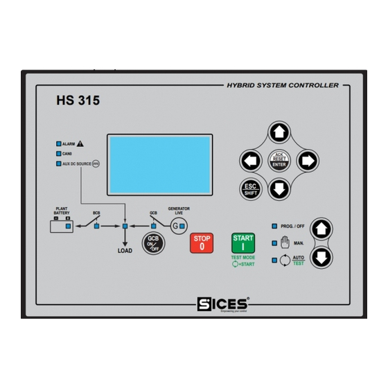
- Page 90 Pushbuttons Function The generator is disabled; warnings and alarms are cancelled. OFF/RESET PROGRAM You can program the parameters. The controller is set for manual gen-set control. Press the START button to start the engine. Press the STOP button to stop the engine. With the engine running and up to speed, press the GCB button for manual MODE UP opening/closing of the GCB circuit breaker.
- Page 91 Pushbuttons Function Navigation buttons of the multifunction display. These buttons let you select the display page in all modes, except in the PROGRAM and HISTORY LOGS modes. In PROGRAM and HISTORY LOGS mode you can scroll the menus and the variables/settings.
-
Page 92: Remote Start
To allow maximum customization of the controller, the status of all the buttons can be used in the AND/OR logics or in the PLC, through the following states: • ST_304: START key pressed. • ST_305: STOP key pressed. • ST_306: GCB key pressed. •... - Page 93 Indicates that the CAN-BUS has been disabled (no expansion modules nor ECU interface connected), or that the controller is not receiving any messages from the ECU of the engine. The auxiliary source voltage (DC, AC, or from digital input) is ...
- Page 94 the controller activates also the digital outputs configured with the function “DOF.3153 - Lamp test”, to switch on external lamps also. The backlight lamp is managed by the controller, which switches it off after a programmable time (P.0492) if no buttons are pressed in the meantime. Press any button to switch the lamp on again, (we recommend using the ESC/SHIFT button as it has no function when used alone).
- Page 95 The display has different display modes with various pages. Mode Description Page identifier PROGRAMMING Programming P.XX L.XX STATUS Status information S.XX MEASURES Electrical measurements M.XX ENGINE Engine measurements E.XX HISTORY History logs H.XX Generally, navigation between modes takes place via buttons UP and DOWN. To view the pages within mode, use the buttons LEFT and RIGHT.
- Page 96 E.01 ENGINE LEGEND: 1 - Status bar 2 - Data area Oil Press. (bar): Coolant Temp. (°C): XXXX Speed (rpm): Fig. 3 - Display areas The top status bar contains information on navigation, times and/or some status information. LEGEND: 1a - Mode identifier E.02 ENGINE 1b - Page identifier 1c - Page title...
- Page 97 The controller manages a high number of parameters that allow the manufacturer, the installer or the final user to configure it to adapt it to specific system requirements. This document does not contain the parameters list (even though many of them are quoted in the description of the controller functions);...
- Page 98 2. At INSTALLER level it is possible to display and modify the User Password and the Installer Password and access all parameters related to configuration, excluding parameters requiring the MANUFACTURER and SICES passwords. 3. At END USER level it is possible to display and modify only the User Password and access parameters that allow adjusting sequence times and base configurations, but do not allow altering the plant's basic operation.
- Page 99 No parameter modification is allowed. When entering “uuu” in “P.0000-Access code”, the operator is identified as “End User” and can to modify all parameters associated to the end user. By entering “iii”, the operator is identified as "installer” but, as no password is associated to the manufacturer, the controller identifies him/her as "manufacturer”.
- Page 100 providing information, no parameter modification will be possible anymore. On the other hand, knowing the “manufacturer” password will allow to cancel or modify the other passwords. This procedure will describe the keyboard and display use. P.07 PROGRAMMING Main Menu 1/05 1 System 2 Sequence 3 Protections...
- Page 101 Current menu name, selected menu item and number of menu items are always displayed in the second line. Menu items (submenus) are displayed in the following lines. The item selected is displayed in REVERSE. Use the ▲ e ▼ buttons to cyclically scroll through the menu to the lower and upper index items (i.e.
- Page 102 Enable function 8 0080 In case the operator wants: • To disable all functions: he/she must set to 0 the relevant parameter. • To enable all functions: the value to be set is the sum 1+2+4+8+16+32+64+128 = 255 (0xFF). • Enable, for example, the functions 3, 4, 6 and 8: the value to be set is the sum 4+8+32+128 = 172 (0xAC) (where 4 is the value associated to the function 3;...
- Page 103 (“nicknames”) to the resources. It is possible to view the symbols in the second column, in place of SICES codes: press ACK/ENTER (as to select a different PLC block) and press ◄►; confirm with ACK/ENTER button. See [6] for SICES codes description, to identify the PLC resources.
- Page 104 This page shows the status of all temporary digital variables (DT_XXX) available for the PLC program. Many pages which alternate every 2 seconds are available to view all digital supports. Keeping ESC/SHIFT pressed, you can impede the rotation of the pages (keeping on the display the page currently viewed).
- Page 105 In this way, information on the system status is provided. You can scroll through the various pages using the LEFT and RIGHT buttons. Page S.01 (STATUS) shows system status information. Part of this information is shown on the top status bar. It contains: •...
- Page 106 • The alarm code specific for the type of engine connected (DTC). • An alphanumerical description (in English) of the problem. If one or more of the above-mentioned information is not available, it will be replaced by dashes or it will simply not be displayed. If multiple diagnostic codes on the engine are active at the same time, they will be cyclically alternated on the display every 2 seconds.
- Page 107 Link For HS315 controllers (equipped with GPRS internal module), the controller shows: • The IP address assigned to the controller by the GPRS network. Some useful information for the connection to “Si.Mo.Ne server.”: Controller name Latitude and Longitude acquired by the GNSS module or set through the parameters of the controller.
- Page 108 • The current managing mode of the fuel pump (MAN-OFF, MAN-ON, AUTO). • The pump status (on/off). • An indication of the fuel level referred to the pump management (starting required, arrest required, in hysteresis). If the pump management is linked to the analogue level sensor, then the controller board displays, by means of a graphic bar, the current fuel level showing also the thresholds for pump start/arrest.
- Page 109 Page S.14 is hidden if no DITEL modules is present. When you press the ACK/ENTER button, the controller changes the visualization through three different modes (LOGICAL STATE, PHYSICAL STATE, BY FUNCTION), showing the statuses of the digital outputs: • LOGICAL STATE: the output's logic command (active or inactive) used by the controller in the management of the operating sequence.
- Page 110 The S.19 (ANALOG OUTPUTS) page displays the command (as percentage) for the analogue outputs of the DANOUT expansion module. The page is available only if the DANOUT expansion module is installed in the system. The S.21 (SI.MO.NE.) page is shown only when the data communication with SI.MO.NE. server (TCP/IP) is enabled (parameter P.0530).
- Page 111 This mode displays all the information on the measurements taken by the Gen-set control module on the electric lines. You can scroll through the various pages using the LEFT and RIGHT buttons. Page M.01 (SYSTEM) displays a wiring diagram of the system. The system can be made up by a maximum of four “sources”: •...
- Page 112 In the bottom-right corner, the symbol of the battery is shown. This allow the operator to immediately understand that he/she is looking at battery measurements (there are very similar pages related to other sources). This page shows a lot of information regarding the charge/discharge process running on the plant battery: •...
- Page 113 • The frequency. • For three-phases system: the line-to-line voltages. • For three-phases system: the phases sequence of the voltages (CW / CCW). • For single-phase system: the line-to-neutral voltage. In the bottom-right corner, the symbol of the generator is shown. This allow the operator to immediately understand that he/she is looking at generator measurements (there are very similar pages related to other sources).
- Page 114 This page is shown only if the controller is configured to acquire the AC voltages of the auxiliary source. It is also hidden if the neutral of the generator is not connected to the controller (P.9618 different from “018”). It shows the three line-to-neutral voltages, with their phases sequence (CW / CCW).
- Page 115 • Model • Serial number Note: the page is hidden if the selected battery type does not provide this information (for example the LG battery). Technical Handbook 97...
- Page 116 The engine related measurements are shown in this mode. The number of pages displayed may depend on the type of engine (J1939, MTU or without communication interface). You can scroll through the various pages using the LEFT and RIGHT buttons. It contains the fundamental measurements for engine management: •...
- Page 117 • Injection time. • Total Engine Hours (SAE J1939: SPN247 These pages are shown only if the CAN-BUS communication to the engine’s ECU is enabled. These pages contain a series of information acquired via CAN-BUS from the engine’s ECU. The amount of information available depends on the type of engine you are connected to. Information not available are automatically hidden.
- Page 118 • Engine Rated Power (SAE J1939: SPN166). • Engine Total Hours of Operation (SAE J1939: SPN247). • Key switch Battery Potential (SAE J1939: SPN158). • Engine Throttle Position (SAE J1939: SPN51). • Error code sent by the ECU with proprietary messages. These pages are used to show the generic measurements acquired by analogue inputs configured with the following functions: •...
- Page 119 SCR: ▪ spn 4331: “SCR Actual Dosing Reagent Quantity (instantaneous)”. ▪ spn 4334: “SCR Dosing Reagent Absolute Pressure”. ▪ spn 4360: “SCR Intake Gas Temperature”. ▪ spn 4363: “SCR Outlet Gas Temperature”. DEF: ▪ spn 1761: “DEF Tank Level”. ▪ spn 3031: “DEF Tank Temperature”.
- Page 120 should be a transient condition: if the level of soot in the filter increases and the ECU cannot regenerate it, at some point the ECU will still apply a derating and eventually it could stop the engine. Forcing of regeneration. It is the opposite command: verifying from the previous lamps the request for regeneration from the ECU, the operator can force it in the moments more favourable to him.
- Page 121 standard). For example, if you use the files related to MAN DATALOGGER, the controller displays all the measurements acquired by those units by two pages (E.19-20). The controller provides up to six pages. The title of each page is defined in the configuration file for the engine, as well as the number of measures shown and their description.
-
Page 122: History Logs
When in operation and not in OFF/RESET mode, the controller performs periodical or on-event recordings that can be partially configured with programming parameters. The controller manages six types of archive: 1. Charge cycles. 2. Events. 3. Fast analogues. 4. Slow analogues. 5. - Page 123 Only for charge cycles: energy transferred to the plant battery during BULK phase (Ah). Only for charge cycles: energy transferred to the plant battery during ABSORBTION phase (Ah). Only for charge cycles: energy transferred to the plant battery during FLOAT phase (Ah). Only for charge cycles: total energy transferred to the plant battery during the cycle (Wh).
- Page 124 0010 Circuit breakers status 0020 Circuit breakers commands 0040 Start/stop requests Fuel pump commands 0080 Charge procedure 0100 Below you will find a table showing the codes of all possible events. Code Ver. Recording cause EVT.1001 01.00 Controller in OFF_RESET mode. EVT.1002 01.00 Controller in MAN mode.
- Page 125 EVT.1074 01.00 Auto reset of the controller. EVT.1075 01.00 Real time clock not valid. EVT.1076 01.00 Real time clock updated. EVT.1077 01.00 New power on of the controller. EVT.1078 01.00 Parameters are reloaded with their default values. EVT.1080 01.00 GCB closure inhibition activated (from digital input). EVT.1081 01.00 GCB closure inhibition deactivated.
-
Page 126: Event Code
5048, where the first digit defines the type (5 = alarm (block)), followed by the anomaly code (048 = Emergency Stop). The most recent event is associated to the highest number. Use the ▲ and ▼ buttons to scroll cyclically trough all recordings. Using the ◄... - Page 127 Measure Page for Page for trend events logs Date/time. Engine battery voltage. Engine oil pressure. Engine coolant temperature. Engine fuel level. Engine speed. Generator voltage (DC). Generator current (DC). Generator power. Plant battery voltage (DC). Plant battery current (DC). Plant battery power. Plant battery temperature.
- Page 128 The fast analogues are recorded at a pace configurable by means of the parameter P.0442 (interval in seconds) and the default interval is 60 seconds. This archive provides a total storage capability of 42 records. Every following record overwrites the older one. The controller records the analogue values described in par.
- Page 129 H.33 HISTORY LOGS 5 DTC-ENGINE 16/16 --------------------- 17/03/2014 14:27:12 DTC:6.6 SPN:100 1 1 Engine oil pressure Data low (shutdown) The second line shows the record currently displayed, out of the total number of records (the maximum number of records is 16). The fourth line shows the recording date and time.
- Page 130 H.51 HISTORY LOGS 5 DTC-BATTERY 5/32 --------------------- 21/01/2019 17:13:56 Warning battery 01: Maximum ambient tempe rature warning • The second line shows the record currently displayed, out of the total number of records (the maximum number of records is 32). •...
- Page 131 Note: the following description assumes that HS315 can open/close the GCB circuit breaker. This is optional: depending on the plants, HS315 can have both opening/closing commands, only the opening command, or none. If HS315 has both commands, then the following description applies.
- Page 132 mode, and when the input goes back on standby, the controller goes back to the mode it was in prior to input activation. • Using the commands from the communication ports. To use these controls, no input configured with the functions described in the previous paragraph should be active. These controls can be enabled by a digital input configured with DIF.2706 function - "...
- Page 133 test is not carried out). If there is second activation of the input during the test, the test is immediately stopped. During this test, the controller closes the GCB circuit breaker, independently from the value configured in P.0222. By properly configuring the parameters: ▪...
- Page 134 ▪ P.0426 (“Days for remote start”). ▪ P.0427 (“Start time for remote start”). ▪ P.0428 (“Stop time for remote start”). These parameters allow selecting the days of the week and a time slot within which the working mode switches from AUTO to REMOTE START. The controller returns to AUTO when interval ends.
- Page 135 ST.003: the output is activated if the board is in TEST. ST.004: the output is activated if the board is in REMOTE START. Technical Handbook 117...
- Page 136 The connection of the auxiliary source to the controller is not mandatory. The controller manages the auxiliary source only if at least one DC or AC voltage or its current are acquired. It is possible to connect AC voltages (single-phase or three-phases) and/or DC voltage. If both DC and AC voltages are connected, DC voltage has higher priority;...
- Page 137 please, remember that disabling both checks is not possible (in this case, auxiliary source is always considered not present). To disable this check, one of the following conditions shall be true: ▪ P.0236 = 0 %. ▪ P.0237 = 200 %. ▪...
- Page 138 Here follows an example about the various threshold used, including default values for a.m. parameters. Parameter Description Default value Voltage in Volts P.0116 Nominal voltage (AC) of the 400 V auxiliary source. Auxiliary source presence 20.0 % threshold P.0203 Auxiliary source low voltage 80.0 % threshold.
- Page 139 • Connecting also the AC voltages. If no one of the previous methods can be used, if the controller acquires the DC voltage, it is used (even if it could not be the real voltage of the auxiliary source). There are various parameters that influence its management: •...
- Page 140 52.8 G band: high If the voltage is in the “B”, “D” or “F” bands, previous status is maintained (hysteresis). For example, if the voltage was in the “E” band and now it is in “D” band, it is considered however “In tolerance”.
- Page 141 In addition, the controller makes available the auxiliary source statuses for the AND/OR logics by means of the following internal statuses: • ST.016 – “Auxiliary source present (voltages/frequency)”. • ST.017 – “Auxiliary source absent or out of thresholds”. • ST.018 – “Delay for auxiliary source in thresholds”. •...
- Page 142 It is possible to connect AC voltages (single-phase or three-phases) and/or DC voltage. If both DC and AC voltages are connected, DC voltage has higher priority; when it cannot be used (see in the following), the controller will use AC voltages. The current is always measured as DC.
- Page 143 Parameter Description Default value Frequency in Hz P.0105 Nominal frequency. 50 Hz P.0228 Threshold for engine stopped 10.0 % (Hz). P.0229 Threshold for engine started 20.0 % (Hz). P.0305 Minimum frequency threshold. 90.0 % P.0307 Maximum frequency 110.0 % threshold. P.0331 Maximum speed...
- Page 144 • P.0226: threshold (percentage of P.0102) under which the engine is considered stopped. • P.0227: threshold (percentage of P.0102) over which the engine is considered started. • P.0301: low generator voltage threshold (percentage of P.0102); under this value the generator cannot be connected to the loads. •...
- Page 145 voltage status: this allows not to switch the loads on the generator if the electrical magnitudes are out of the tolerance band, even though protections are disabled. Thresholds P.0391 and P.0393 are used for protections only; they are not used for detecting the status of the generator.
- Page 146 1800 Band H: Over speed The only managed hysteresis band is the one used to diagnose the stopped or running engine status. The generator detects no difference between the “G” and “H” bands. Many parameters influence generator voltage measures: • P.9641: Nominal voltage (DC).
- Page 147 If the voltage is in the “B”, “D” or “F” bands, previous status is maintained (hysteresis). For example, if the voltage was in the “E” band and now it is in “D” band, it is considered however “In tolerance”. On the contrary, if voltage was in the “C” band and now is in “D” band, it is considered “Low”.
- Page 148 237 - Generator status not available. 001 - Minimum generator's voltage. 056 - Low generator's voltage. 059 - High generator's voltage. 002 - Maximum generator's voltage. 011 - Reverse current on the generator. 015 - Trip on GCB circuit breaker. 016 - Maximum generator current (50).
- Page 149 • One warning for low frequency (W058, parameters P.0202, P.0395, P.0396). • One warning for high frequency (W060, parameters P.0202, P.0397, P.0398). • One alarm (block) for maximum frequency (A004, parameters P.0202, P.0307, P.0308). HS315 implements 4 different protections for the generator voltage. They can work with both AC and DC voltages.
- Page 150 It is possible to connect DC voltage only. The current is always measured as DC. The connection point of the voltage must be “before” the LCB circuit breaker (if present). The controller acquires the voltages and the current of the loads for: •...
- Page 151 Starting from version 1.09, HS315 manages up to 8 secondary contactors, which can be used to connect different groups of loads to the storage battery (or to the generator). Note: if an LCB circuit breaker exists (see 9.8), it must be placed upstream of the secondary contactors: if it opens, the loads connected to any secondary contactor must result unsupplied.
- Page 152 Parameter Description Value P.9642 Capacity (C) at nominal Set the rated capacity. discharge current P.9643 Nominal discharge Set the current provided by the manufacturer, if current. not provided set 1/20 of P.9642 P.9644 Capacity at discharge current #2. P.9645 Discharge current #2. 0,00 P.9646 Constant of Peukert.
- Page 153 • 1: Enabled. The controller reports the failure of the temperature sensor ("W213 - broken wire") if parameter P.9636 is different from zero and the resistance measurement exceeds 333 ohms. The same warning is also activated if voltage or current temperature compensation is required, but temperature measurement is not available (for example if P.9636 is set to 0).
- Page 154 PI controllers’ parameters can also be modified while the system is running, even from the operator panel. It is advisable to make changes using the BoardPrg3 program, available free of charge on SICES s.r.l. website. 1) Set "P" at an initial value (0.100) and "I" at 0000.
- Page 155 3) Measure the period of oscillation (the time between two consecutive voltage peaks). 4) Set "P" to a slightly lower value than the one obtained by dividing the current value by 2.2. 5) Set the "I" to the calculated value by dividing 1.2 for the oscillation period measured before (in seconds).
- Page 156 Charge duration in FLOAT mode. P.9687 P.9680 Charge limit. P.9688 P.9681 Normally, HS315 performs the "standard" charge cycle. It executes the "Full" charge cycle in two conditions: • If a digital input configured with the function DIF.2321 ("Full charge") is active at the start of the charge cycle.
- Page 157 Note: during this stage, the generator is supplying the loads also. It is then possible that the sum of the current absorbed by the loads and the current to be supplied to the battery becomes greater than the generator rated current (P.9502): in this case, the current setpoint is limited in order not to exceed the generator rated current.
- Page 158 In this stage, the charge of the battery is made at fixed voltage. The voltage setpoint is configurable by the parameter P.9679 (“Charge (full) voltage in FLOAT mode”) or P.9686 (“Charge (standard) voltage in FLOAT mode”) (see 9.5.7). This stage ends after the time configured by P.9680 (“Charge (full) duration in FLOAT mode”) or P.9687 (“Charge (standard) duration in FLOAT mode”) (see 9.5.7).
- Page 159 By assigning the AIF.2113 function to a virtual analogue input, it is possible to compile a table (as in the previous example), where the first column indicates different engine powers (% of P.0125). The second column, instead, contains the corresponding optimized engine speeds (%).
- Page 160 P.0831: set to 0 if an increase in the output should corresponds to an increase in the voltage. Set to 1 if an increase in the output should corresponds to a decrease in the voltage. P.0856: allows you to set the value for the analogue output corresponding to an internal command of 0% (default 0%).
- Page 161 Configure the analogue output (parameter P.6001 for output 1) with function AOF.1003 ("Speed regulator (generic)"). In this case, the output scaling can be done by means of a conversion curve. Speed governor connection via CANBUS Normally, HS315 makes the internal speed request (0-100%) correspond to a real speed range of +/- 120 rpm, with respect to the rated speed.
- Page 162 • EVT.1521: start of the “standard” charge cycle. • EVT.1522: start of the “full” charge cycle. The following functions, for the configuration of analogue outputs, are linked to the plant battery management. The outputs are managed based on a plant battery analogue value. Use the "conversion curves"...
- Page 163 Power transferred to the battery during charge cycles (Wh) M.05 Number of discharge cycles M.05 Energy supplied by the battery during charge cycles (Ah) M.05 Power supplied by the battery during charge cycles (Wh) M.05 Estimation of the remaining charge level (Ah) M.02 Estimation of the remaining charge level (%) M.02...
- Page 164 In AUTO mode, whatever the status of the plant, two causes can anyway inhibit the gen-set automatic start: • operational time range. • digital input. When there is an inhibition active, a flashing lock is displayed in the top right corner of the display.
- Page 165 HS315 can start, stop and protect the engine by means of a series of thresholds on the acquired measures (oil pressure, coolant temperature, speed etc.). HS315 allows specifying the rated power of the engine (P.0125 parameter, in kW). It is important to set this figure, because the thresholds for some protections are expressed as its percentage.
- Page 166 • The board can also read the engine rotation speed directly from the electronic control unit (ECU) of the engine itself through the CAN0 CAN-BUS. To do this, it is simply necessary to enable the CAN-BUS (P.0700 different from zero), and P.0110 and P.0111 parameters should be set to zero.
- Page 167 There are seven possible ways to define whether the engine is running or not: • Directly from the electronic control unit (ECU) of the engine (if connected via CAN0 CAN-BUS, P.0700 <> 0). • Engine speed (RPM) The engine is in motion if the rotation speed is above P.0225 threshold ("Started engine threshold (rpm)";...
- Page 168 P.0229=0. P.0228 > P.0229. • From generator DC voltage. The engine is in motion if the tension is above P.9652 threshold ("Started engine threshold (Vdc)"; it is considered stopped if the tension is below P.9651 threshold ("Stopped engine threshold (Vdc)"). This control is not used P.9651=0.
- Page 169 • ST.132 (START). • ST.133 (STOP). • ST.134 (IDLE). • ST.135 (PREHEAT). • ST.136 (PRELUBE). As follows, the controls are described individually. Note: for electronic engines connected via CAN0 CAN-BUS to HS315, many of these controls are managed directly through the CAN-BUS connection, and therefore it is not necessary to configure the outputs.
- Page 170 If the lubricant low-pressure threshold is not configured, but minimum pressure threshold is configured (P.0341 <> 0), when the measured pressure is higher than the threshold. • If the board does not acquire the measurement of lubricant pressure, or if both P.0339 and P.0341 thresholds are set to zero: If the digital input is configured to acquire "oil low pressure"...
- Page 171 In manual mode, the board always performs only one starting attempt, and then it always performs it on battery #1. The automatic starting sequence is: • BATT1 output enabled, BATT2 output disabled. • 2-second wait (note 1). • First crank attempt. •...
- Page 172 The ECU_ENABLE control should be used to give a consent to the starting of electronic control units of the engines. Lacking this consent, it is reflected in the shutdown of the fuel injection system: therefore, without this consent then the engine cannot start, but instead it will be stopped if it was running.
- Page 173 The STOP control is activated at the beginning of the stopping cycle, at the same time when the ECU_ENABLE control is removed. The STOP control will remain active for the time set with P.0213 parameter ("Duration of the stop control"). Note: If the engine stops in a shorter time, and a restarting of the engine is required, the STOP control is disabled before.
- Page 174 This function is particularly useful when HS315 should work with a MC100 board. In this case, in fact, it is not possible to use the "inhibition to automatic intervention" function to prevent the starting of the engine during the pre-ventilation phase (or others): MC100, in fact, when it wants to start a generator, switches the related HS315 to REMOTE START, where the requests for "inhibition to automatic intervention"...
- Page 175 • With a digital input configured with DIF.2034 function ("Manual stop control"). This input is managed exactly as the STOP key: same as said above. • It is possible to control the stopping of the engine manually with a control through the serial ports.
- Page 176 • With an emergency procedure. This procedure requires immediate engine stop, without engine cooling cycle. It applies if: The key switch is turned on OFF/RESET Any anomaly described as a "shutdown" is activated. In automatic mode, the stop commands from panel (STOP button, if not disabled by bit 0 of parameter P.0495), from serial port and from SMS are included in this category since they activate the alarm A07 (manual stop in auto mode).
- Page 177 P.0214 parameter ("Duration of the stopping cycle"): if at the end of this phase the engine has not stopped, A021 shutdown is activated - "Failure to stop". Note: normally the stopping cycle lasts P.0214 seconds even if the engine stops in a shorter time.
- Page 178 • DOF.3062 the output will be activated if the engine is in motion and if the “delay before supplying” (P.0218) has been performed. • DOF.0103 (Logics AND/OR) ST.032: the output will be activated if the engine is in motion. ST.033: the output will be activated if the engine is in motion and if the “oil protection masking”...
- Page 179 042 - Minimum oil pressure (from measure). 142 - Minimum oil pressure (from CANBUS). 054 - High oil temperature (from measure). 158 - High oil temperature (from CANBUS). 035 - Maximum oil temperature (from measure). 159 - Maximum oil temperature (from CANBUS). 037 - Low battery voltage (from measure).
- Page 180 The following functions, for the configuration of analogue outputs, are linked to engine management. The outputs are managed based on an engine analogue value. Use the "conversion curves" to adapt the single value to the output (0-100%): • AOF.3001 (“engine speed”). •...
- Page 181 To use this function: • The level analogue transducer should be connected to one of the analogue inputs of HS315 or to DIVIT expansion modules. The utilized analogue input should be configured through AIF.1220 functions (dedicated to VDO sensor, 0%-180 Ohm, 100%-0 Ohm) or through AIF.1221 function (configurable).
- Page 182 HS315 uses two controls to manage the fuel pump, that can be associated to any digital output (P.3001 parameter and subsequent ones) with the functions: • DOF.1032 (“Fuel pump”). • DOF.1034 (“Fuel pump solenoid”). The output for the pump control is mandatory (otherwise this function is disabled). The output for the electromagnetic valve is optional.
- Page 183 storage tank. The pump is stopped until W064 early warning is activated: when the operator “cancels” it, the pump restarts with another cycle. • HS315 allows configuring the electric source that must supply the pump, through P.0406 parameter (“Supplying of the fuel pump”): 0: generator voltage.
- Page 184 It often happens that in the control panel of a generator controlled by HS315 there is no standard battery charger to keep the engine cranking battery charged. It is normally charged by the engine’s battery charger, when the engine is running. Usually, in this type of system, the engine is started several times a day, so the cranking battery should remain charged.
- Page 185 The controller manages up to 4 circuit breakers: • BCB (“Battery circuit breaker”). • GCB (“Generator circuit breaker”). • LCB (“Loads circuit breaker”). • ACB (“Auxiliary source circuit breaker”). The management is identical for all. Each circuit breaker can be present or not (in this case the controller works as if is present and always closed).
- Page 186 • DOF.2004 - “ACB steady opening command”. DOF.2034 - “GCB steady closing command”. DOF.2044 - “BCB steady opening command”. DOF.2054 - “LCB steady opening command”. For the GCB: the controller disables this output when it must open the breaker. For the other circuit breakers: the controller enables this output when it must open the breaker.
- Page 187 The delay associated to the input is used as filter time for acquiring the contact. If the input is activated for the configured delay, the controller activates an alarm (block, for the GCB circuit breaker) or a latched warning (for the other circuit breakers): these anomalies avoid the closure of the related circuit breakers.
-
Page 188: Holding Register
The following conditions force the opening of the GCB circuit breaker (and avoid its closure), but only if one closure command for GCB has been configured: • If the controller is in OFF mode. • If the engine is not running. •... - Page 189 • The trip of the minimum/maximum temperature protections for the plant battery. • The trip of the maximum current protections (instantaneous and time dependant) for the plant battery. • If the BCB is opened, the controller avoids its closure if the plant battery voltage is above the maximum threshold or below the minimum one.
- Page 190 In MAN mode, the operator can decide which breaker must be opened or closed and can interacts with the controller with the manual opening and closing commands. Manual opening commands are accepted only if at least one digital output of the controller is configured as “opening command”.
- Page 191 ▪ 41 and 42 to open the ACB. ▪ 43 to close the ACB. ▪ 44 and 45 to open the BCB. ▪ 46 to close the BCB. ▪ 47 and 48 to open the LCB. ▪ 49 to close the LCB. See 9.8.3.
- Page 192 ▪ Lamp off: breaker open. ▪ Blinking lamp (during 25% of time): the controller sent the breaker a 'close' command, yet it is open. ▪ Blinking lamp (during 75% of time): the controller sent the breaker an 'open' command, yet it is closed. The following functions for the configuration of the digital inputs are linked to circuit breakers management (besides those described for circuit breakers direct controls): •...
- Page 193 • EVT.1437: LCB closed. • EVT.1438: LCB opened. The controller records any “GCB open” forcing in the events log, if it is enabled with bit 6 of the P.0441 parameter: • EVT.1080: GCB closure inhibition activated (from digital input). • EVT.1081: GCB closure inhibition deactivated.
- Page 194 • ST.079 - "ACB closure command (stable)”. • ST.088 - "GCB closure inhibited by contact”. • ST.090 - "GCB closure inhibited by serial port”. • ST.091 - "GCB closure inhibited by the protection of the circuit breaker”. • ST.093 - "GCB closure inhibited for battery disconnected”. •...
- Page 195 This chapter describes all the anomalies managed by the controller. Some of them act as protection for the loads, for the generator or for the engine. There is also signalling of specific events in the plant management. Before describing them in detail, some definitions are required.
- Page 196 • By using a command from the communication ports. To send the command you need to write in sequence (within 5 seconds): HOLDING REGISTER 101: enter the password configured with the parameter P.0004. HOLDING REGISTER 102: enter the value “51”. Parameter P.0491 (Horn duration) influences the management of the controller's horn.
- Page 197 HOLDING REGISTER 102: enter the value “53”. • Using a digital input configured with the feature DIF.2001 - “Command for resetting alarms”. When the input becomes active, the controller executes a reset of all anomalies. When the controller performs an anomaly reset, it also activates for one second the outputs configured with the function DOF.3151 - “Reset of the anomalies”.
- Page 198 To disable: P.0302=0 Enabled in: *MAN, AUTO, TEST, REMOTE START Override: Generator, Full. This protection, when possible, works on the DC voltage of the generator. If not possible (GCB closed), if AC voltages are available it works with them, otherwise it will never be activated. It is only enabled if the engine has been started by the controller (if the command for the fuel solenoid is activated) and it is disabled during the crank/stop cycles.
- Page 199 Type: Alarm Related parameters: P.0105 Nominal frequency. P.0133 Engine's nominal speed (primary). P.0134 Engine's nominal speed (secondary). P.0307 Maximum frequency threshold. P.0308 Maximum frequency delay. To disable: P.0308=0 Enabled in: MAN, AUTO, TEST, REMOTE START Override: Generator, Full. This protection works on the generator frequency if the AC voltages have been connected, Otherwise, if possible, it works on the engine speed.
- Page 200 If the current rises above the threshold, the protection activates with a time inversely proportional to the overcurrent. To correctly set the thresholds, perform the following steps: • Set the maximum current threshold with the parameter P.0309, as a percentage of the rated current (P.9502).
- Page 201 To disable: Bit 0 of P.0495=1 Enabled in: AUTO, TEST, REMOTE START Override: This protection is always enabled if the stop command comes through the communication ports or via SMS; it can be disabled for the STOP button by setting the bit 0 of parameter P.0495 to 1.
- Page 202 Type: Warning / deactivation Related parameters: P.2001 Function of the input 01 or equivalent for the other inputs P.2002 Delay for the input 01 or equivalent for the other inputs. To disable: P.2002 = 0 Enabled in: MAN, AUTO, TEST, REMOTE START Override: This protection is enabled only when one of the digital inputs of the controller is configured to acquire the GCB status (function DIF.3001 - “Status of GCB circuit breaker”) (in parameter...
- Page 203 Related parameters: P.2001 Function of the input 01 or equivalent for the other inputs P.2002 Delay for the input 01 or equivalent for the other inputs. To disable: P.2002 = 0 Enabled in: MAN, AUTO, TEST, REMOTE START Override: This protection is enabled only when one of the digital inputs of the controller is configured to acquire the external over speed contact (feature DIF.4251 - “Over speed”) (in parameter P.2001 or equivalent for the other inputs) and if a time other than zero has been set for said input (parameter P.2002 or equivalent).
- Page 204 To disable: P.0214 = 0 Enabled in: MAN, AUTO, TEST, REMOTE START Override: Full This protection is activated if the engine does not stop within the time set in P.0214 (since the stop command). Type: Alarm Related parameters: P.0211 Number of starts attempts. To disable: Enabled in: AUTO, TEST, REMOTE START...
- Page 205 Override: Engine. This protection is enabled only when one of the digital inputs of the controller is configured to acquire the minimum fuel level contact of the float (function DIF.4211 - “Minimum fuel level”) (in parameter P.2001 or equivalent for the other inputs) and if a time other than zero has been set for said input (parameter P.2002 or equivalent).
- Page 206 P.0346). It is activated if the level measure remains continuously below or equal to threshold P.0345 (in percentage) for time P.0346. Type: Warning Related parameters: P.2001 Function of the input 01 or equivalent for the other inputs. P.2002 Delay for the input 01 or equivalent for the other inputs. To disable: P.2002 = 0 Enabled in:...
- Page 207 Type: Warning Related parameters: P.4009 Function of the analogue input 2 (JQ) or equivalent for the other inputs. P.0216 Time mask for engine protections. P.0335 High coolant temperature threshold. P.0336 High coolant temperature delay. P.0700 Engine type. To disable: P.0336 = 0 Enabled in: MAN, AUTO, TEST, REMOTE START Override:...
- Page 208 controller is configured to acquire such measure - function AIF.1110 or AIF.1111 in parameter P.4009 or equivalent for the other inputs) and if a time other than zero has been set for the protection (parameter P.0338). It is only enabled if the engine has been started by the controller (if the command for the fuel solenoid is activated) and is disabled in the engine start/stop phases.
- Page 209 It is always enabled except when the cranking motor is activated. It is activated if the battery voltage is continuously above threshold P.0364 for time P.0365. The threshold P.0364 is expressed as a percentage of the rated battery voltage which is not configurable but is automatically selected by the controller between 12 e 24 Vdc.
- Page 210 Override: Engine. This protection is enabled only when one of the digital inputs of the controller is configured to acquire the external minimum oil pressure contact (function DIF.4221 - “Minimum oil pressure”) (in parameter P.2001 or equivalent for the other inputs) and if a time other than zero has been set for said input (parameter P.2002 or equivalent).
- Page 211 P.0216 Time mask for engine protections. P.0339 Low oil pressure threshold. P.0340 Low oil pressure delay. P.0700 Engine type. To disable: P.0340 = 0 Enabled in: MAN, AUTO, TEST, REMOTE START Override: This protection is enabled if the controller acquires the measurement of the oil pressure (directly from the ECU of the engine or if one of the analogue inputs of the controller is configured to acquire such measure - function AIF.1000 or AIF.1001 in parameter P.4009 or equivalent for the other inputs) and if a time other than zero has been set for the protection...
- Page 212 It is activated after P.0438 days since parameter P.0438 was last set (the check is done at each hour change). It cannot be cancelled even disconnecting the controller's power supply. It can be cancelled only by setting P.0438 again, setting it to zero to disable the function or confirming the actual value or setting a new one.
- Page 213 P.0421 Generator enable days. P.0422 Generator enable start time. P.0423 Generator enable stop time. P.0426 Days for remote start. P.0438 Interval of days for maintenance. To disable: Set the clock Enabled in: MAN, AUTO, TEST, REMOTE START Override: This warning is always enabled. It is activated if the controller detects a not-valid clock status, and functions using the clock are set, such as the weekly test (P.0420), operation enabling time (P.0421, P.0422, P.0423), generator start forced (P.0426) and days to next maintenance (P.0438).
- Page 214 Type: Warning Related parameters: P.0105 Nominal frequency. P.0133 Engine's nominal speed (primary). P.0134 Engine's nominal speed (secondary). P.0397 Maximum frequency threshold. P.0398 Maximum frequency delay. To disable: P.0398 = 0 Enabled in: MAN, AUTO, TEST, REMOTE START Override: This protection works on the generator frequency if the AC voltages have been connected, Otherwise, if possible, it works on the engine speed.
- Page 215 To disable: P.0354 = 0 Enabled in: MAN, AUTO, TEST, REMOTE START Override: This protection is enabled if the controller acquires the measurement of the coolant temperature (directly from the ECU of the engine or if one of the analogue inputs of the controller is configured to acquire such measure - function AIF.1110 or AIF.1111 in parameter P.4009 or equivalent for the other inputs) and if a time other than zero has been set for the protection (parameter P.0354).
- Page 216 Related parameters: P.2001 Function of the input 01 or equivalent for the other inputs P.2002 Delay for the input 01 or equivalent for the other inputs. To disable: P.2002 = 0 Enabled in: MAN, AUTO, TEST, REMOTE START Override: This protection is enabled only when one of the digital inputs of the controller is configured to acquire the BCB status (function DIF.3006 - “Status of BCB circuit breaker”) (in parameter P.2001 or equivalent for the other inputs) and if a time other than zero has been set for said input (parameter P.2002 or equivalent).
- Page 217 Type: Alarm Related parameters: P.0700 Engine type. P.0704 Can-Bus alarms disable mask. To disable: bit 7 of P.0704 on Enabled in: MAN, AUTO, TEST, REMOTE START Override: Engine. This protection is enabled only if the board is connected to the engine via the CAN BUS (P.0700 different from zero).
- Page 218 Related parameters: P.0700 Engine type. P.0704 Can-Bus alarms disable mask. To disable: bit 0 of P.0704 on Enabled in: MAN, AUTO, TEST, REMOTE START Override: This protection is enabled only if the board is connected to the engine via the CAN BUS (P.0700 different from zero).
- Page 219 To disable: bit 14 of P.0704 on Enabled in: MAN, AUTO, TEST, REMOTE START Override: This protection is enabled only if the board is connected to the engine via the CAN BUS (P.0700 different from zero). It is activated when the engine signals the active state of its yellow lamp over the CAN BUS.
- Page 220 Related parameters: P.2001 Function of the input 01 or equivalent for the other inputs P.2002 Delay for the input 01 or equivalent for the other inputs. To disable: P.2002 = 0 Enabled in: MAN, AUTO, TEST, REMOTE START Override: This protection is enabled only when one of the digital inputs of the controller is configured to acquire the external contact that signals the trip of the over current protection of the circuit breaker (function DIF.3012 - “Trip of ACB circuit breaker”) (in parameter P.2001 or equivalent for the other inputs) and if a time other than zero has been set for said input (parameter P.2002...
- Page 221 Type: Warning Related parameters: P.9701 Battery temperature hysteresis. P.9706 High battery temperature threshold. P.9707 High battery temperature delay. To disable: P.9707 = 0 Enabled in: MAN, AUTO, TEST, REMOTE START Override: This protection is activated if the measure of the plant battery temperature remains continuously above the threshold P.9706 for time P.9707.
- Page 222 Type: Warning Related parameters: P.9641 Nominal voltage (DC). P.9711 Battery voltage hysteresis. P.9716 High battery voltage threshold. P.9717 High battery voltage delay. To disable: P.9717 = 0 Enabled in: MAN, AUTO, TEST, REMOTE START Override: This protection is activated if the measure of the plant battery voltage remains continuously above to threshold P.9716 (percentage of the rated voltage P.9641) for time P.9717.
- Page 223 The protection will be activated exactly after this time (P.9725) if the current is constantly equal to the threshold P.9724 multiplied by , in a shorter time if the current is higher; in a longer time if the current is lower; and it will never do if the current is lower than P.9724 Type: Latched warning Related parameters: P.9721 Battery current hysteresis.
- Page 224 Override: This protection is only enabled if the controller is connected to an electronic battery (P.9761 <> "0" and P.0451 or P.0471 = "3"). It is activated when the battery indicates the presence of at least one alarm. Type: Warning Related parameters: P.9761 Battery model.
- Page 225 Enabled in: MAN, AUTO, TEST, REMOTE START Override: This protection is activated if the measure of the auxiliary source current remains continuously above to threshold P.9736 for time P.9737. Type: Latched warning Related parameters: P.9731 Auxiliary source current hysteresis. P.9738 Auxiliary source reverse current threshold. P.9739 Auxiliary source reverse current delay.
- Page 226 Enabled in: MAN, AUTO, TEST, REMOTE START Override: HS315 performs a time-dependent current protection (therefore, the higher the current overload, the shorter the reaction time) The curve used is called EXTREMELY INVERSE with function I t. See description for anomaly 006. The protection will be activated exactly after this time (P.9755) if the current is constantly equal to the threshold P.9754 multiplied by , in a shorter time if the current is higher;...
- Page 227 To disable: P.0142=0 e P.0143=0 Enabled in: MAN, AUTO, TEST, REMOTE START Override: This warning is enabled if a number of analogue modules other than zero has been set (in parameters P.0142 or P.0143). It activates if one or more CAN-BUS (EXBUS) measures are not properly configured or in case of faulty sensor.
- Page 228 Type: Warning Related parameters: P.9641 Nominal voltage (DC). P.9741 Loads voltage hysteresis. P.9744 Low loads voltage threshold. P.9745 Low loads voltage delay. To disable: P.9745 = 0 Enabled in: MAN, AUTO, TEST, REMOTE START Override: This protection works on the DC voltage of the common bar. Its purpose is to protect the loads from low voltages.
- Page 229 the plant battery). Since there isn’t a DC measure for the common bar, the protection works with the loads DC voltage if LCB is closed. If LCB is opened, and both generator and auxiliary source are generating currents, the protection uses another voltage, evaluated in the following order: •...
- Page 230 • JH4 can be used for auxiliary source neutral only (warning). The controller is configured to acquire at least one AC voltage of the auxiliary source: in this case, the terminal JH-4 can be used only to acquire the neutral (otherwise leave P.9618 = “000 –...
- Page 231 • DIF.4013 – “General deactivation (after oil delay)”. • DIF.4014 – “General alarm (block) (after oil delay)”. If the input stays continuously "active" for the time configured, and if the time set by means of the P.0216 parameter (Engine protections mask time) has elapsed, an anomaly of the related type is activated: the message shown is the one set by means of the related parameters.
- Page 232 parameters. Remark: if engine’s protections override function is enabled, this anomaly becomes a warning. See [1] to check the correspondence between alarm code and analogue input. Type: Warning Related parameters: - To disable: Enabled in: MAN, AUTO, TEST, REMOTE START Override: The protection is enabled only when a valid PLC program has been transferred to the board.
- Page 233 The controller manages a separate operating time counter when this engine override mode is active. WARNING: using this function may seriously damage the engine. SICES cannot, in any case, be held responsible for damages, resulting from the use of the OVERRIDE function.
- Page 234 At the end of the document [1] there is a table that summarize all the anomalies; if in the “Over” column the character “G” is present, it means that, in presence of the generator protections override, that anomaly becomes a warning. In the same way, in the description of the anomalies in this document (chapter 10), for each of them it is indicated to which override request it is related: if the text “generator”...
- Page 235 • Counter for the total power (Wh) transferred to the battery during the charge cycles. • Total number of discharge cycles. • Counter for the total energy (Ah) absorbed from the battery during the discharge cycles. • Counter for the total power (Wh) absorbed from the battery during the discharge cycles.
- Page 236 • P.0415: hours. • P.0416: minutes. • P.0417: seconds. You can set the clock manually, but also in the following two ways: • Using the Modbus protocol through the communication ports. The BoardPrg3 software, for example, allows the synchronization of the controller clock with the clock of the PC (it acts on the previous parameters).
- Page 237 • "4 - Automatic via Si.Mo.Ne.": the automatic management of the time is based on the time received from Si.Mo.Ne. The parameter P.0409 allows to select (with a resolution of 15 minutes) which is the time difference when the daylight save time is activated (in Italy we have a difference of 1 hours, so this parameter must be set to 4 (15 min *4 = 1 hour)).
- Page 238 • P.0419: allows to set start time for the TEST (Hours and minutes). • P.0420: allows to configure the TEST duration (in minutes). P.0420 sets the duration instead of an end test time. This is due to the same parameter being also used for TEST activated by an SMS command.
- Page 239 • P.0426: allows to specify in which days of week the engine is forced to start automatically. It is a bit-configurable parameter; each bit of the parameter corresponds to a day of the week. The value to be set for the parameter is the sum of the value fields in the following table related to the days needed.
- Page 240 Using BoardPrg3 software, it is very easy to select whether a calendar is “weekly” or “monthly”. If you want to use the parameters of the controller, you must act on the parameter P.1900. It is a bit-field parameter; one bit is provided for each calendar: Value Hexadecimal Calendar...
- Page 241 0100 September 0200 October 1024 0400 November 2048 0800 December The parameter must be set with the sum of the values of the required months (in hexadecimal notation). For “monthly” calendars, is then possible to select the days of the month for the activation of the internal bit (at least one day must be selected, it is even possible to select all days).
- Page 242 262144 00040000 Tuesday 524288 00080000 Wednesday 1048576 00100000 Thursday 2097152 00200000 Friday 4194304 00400000 Saturday The parameter must be set with the sum of the values of the required days (in hexadecimal notation). Selecting a day of the week (Sunday for example), it is then possible to select if all “Sundays” in the month must be used or only some of them.
- Page 243 Select “weekly” (bit 14 of P.1900 = “1”). Last Sunday of October: ▪ Select “October” (P.1957 = “0200”). ▪ Select “Sunday”, “Last” (P.1958 = “00010010”). The activation should happen at 02:00: ▪ Select “2:00” as start time (P.1959). ▪ Select “2:01” as end time (P.1960). •...
- Page 244 Moreover, each timer provides the following five parameters (the list refers to the timer 1): • P.2901: function of the timer 1. • P.2902: Activation delay format for the timer 1. • P.2903: Activation delay for the timer 1. • P.2904: Deactivation delay format for the timer 1.
- Page 245 The internal bit is reset with the delay P.2904 – P.2905 from when the “activation condition” becomes false. • 2 – Pulse. The internal bit is reset while the “reset condition” is true. The internal bit is set for the time configured with P.2902 – P.2903 each time the “activation condition”...
- Page 246 • P.0455 – Events for alerts. This parameter (bit-field) allow to select the conditions that must force the controller to send an SMS or to make a data call. Bit Value Hexadecimal Event 0001 For alarms and deactivations. 0002 Per warnings. 0004 Per engine started.
- Page 247 If any of the areas is not valid, the normal operating sequences are not carried out until the operator presses the “ENTER + EXIT” buttons: in fact, the situation must be taken note of, because it may cause malfunctions (for example, imagine what would happen if the invalid area were the one of the parameters) Only when the operator presses “ENTER + EXIT”...
- Page 248 Charge/discharge current M.15 Average temperature °C M.15 Charge level M.15 Bus voltage Central temperature °C Lateral temperature (1) °C Lateral temperature (2) °C Electronic card temperature °C Central heater command Lateral heaters command Date/time Alarms/warnings S.02 I/O status LED lamps status Model M.16 Serial number...
- Page 249 • 15: Heaters error alarm • 16: Thermocouple error alarm • 17: String voltage measure error alarm • 18: String current measure error alarm • 19: Hardware failure alarm • 20: Hardware emergency alarm • 21: Maximum heatsink temperature alarm •...
- Page 250 Data Rack Module x page page Battery voltage M.15 Charge/discharge current M.15 Average temperature °C M.15 Charge level M.15 Charge limit Discharge limit Number of modules Alarms/warnings S.02 *: these data are not displayed; they are readable by HS315 via Modbus. HS315 can use highlighted data instead of its measured ones.
- Page 251 • Cell Voltage Difference Alarm • Module Temp Difference Alarm • Temp Out of Limit Fault • Current Out of Limit Fault • Cell Over Voltage Fault • Cell Under Voltage Fault • Over Charging Current Fault • Over Discharging Current Fault •...
- Page 252 HS315 can use highlighted data instead of its measured ones. The management of the alarm/warnings coming from the battery is like that of CANBUS engines. In practice, HS315 handles only two cumulative: • W226: cumulative warnings of the batteries’ electronic cards. •...
- Page 253 • A mosfet is over temperature • Heater failure • Battery current sensor out of range • Auto-test failure • Low SOH • Inconsistent temperatures • Low uc supply voltage (3.3V)"); • Low uc supply voltage (5V)"); • Unbalanced cells •...
- Page 255 SICES s.r.l. reserves the right to modify this document without prior notice. SICES has made any effort to ensure that the information herein provide are correct; in any case SICES does not assume any liability for the use these information.
Need help?
Do you have a question about the HS 315 and is the answer not in the manual?
Questions and answers