
Subscribe to Our Youtube Channel
Related Manuals for Sices GC250


Summary of Contents for Sices GC250
- Page 1 File name: EAAM057703EN.docx Rev. 03 Date: 04/08/2020 Document ID: EAAM0577 Product: GC250...
-
Page 2: Table Of Contents
Operating modes ....................22 7.2.1 Off/Reset ...................... 22 7.2.2 Automatic ..................... 22 7.2.3 Manual......................23 7.2.4 TEST ......................24 8 Date/time setting ......................25 9 Fuel pump (if present) ....................25 Operating selection ..................... 25 Energy saving ......................26 GC250 user manual... - Page 3 Proper recycling and disposal helps to preserve nature and prevent harmful effects on health and the environment. This manual describes the GC250 controller. BLOCK: it is used to indicate an anomaly that makes the generator impossible to operate and causes the automatic and immediate shutdown of the engine with an emergency procedure.
- Page 4 ISLAND: application in which the generator feeds the loads without being in parallel with the mains. SPM (Single Prime Mover): island application where the mains is never available, and the genset is always running. SSB (Single Stand By): island application where the genset runs only in case of mains failure. GC250 user manual...
-
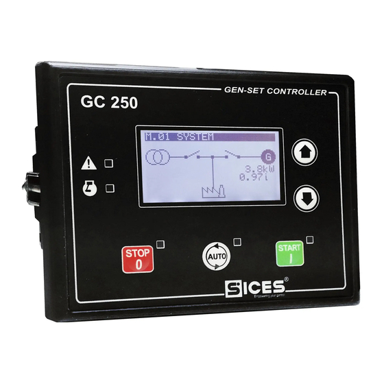
Page 5: Front Panel
Fig. 1 – Front panel Legend 1) Buttons 2) Indicators Commands are available by five buttons (1a, 1b). Five lamps are available for indications (2a, 2b). GC250 user manual 5... - Page 6 The START button must be pressed and released again to perform a new start attempt. If pressed together with the STOP button while the controller is powered, it allows access to the special functions. GC250 user manual...
- Page 7 The controller is in another operating mode. Indicates the presence of at least one block or one deactivation. ALARM Indicates the presence of at least one warning. No anomalies. Indicates engine running. ENGINE RUNNING Indicates engine stopped. GC250 user manual 7...
-
Page 8: Contrast Adjustment
Finally, keeping the DOWN button pressed for at least one second, it selects and shows the desired mode. The UP and DOWN buttons are also used to scroll the pages within the selected display mode. GC250 user manual... - Page 9 The title shows the operating mode of the controller (2), which can be OFF, MAN, AUTO, TEST, and REMOTE START. It is useful for the operator, as it is displayed even if he is accessing other pages or display modes. GC250 user manual 9...
- Page 10 WARNING! Critical parameters must not be changed by the user. The “log in” operation is valid for a period of about 10 minutes from the end of programming. After this period, the access code must be entered again to access programming. GC250 user manual...
- Page 11 The protections and alarms are generally configurable by means of specific parameters. Normally, the trip time associated with the protection can also be configured. INFORMATION! By setting the tripping time to 0, the protection is disabled. GC250 user manual 11...
- Page 12 To exit the PROGRAM function and return to the main screen, press the STOP button repeatedly. GC250 user manual...
-
Page 13: Operating Modes
For many of this information, a time is also shown; for example, during the engine cooling cycle the time remaining at the end of this cycle is shown. The S.02 (ANOMALIES) page is automatically displayed in case of a new anomaly. For each anomaly, the following is shown: GC250 user manual 13... - Page 14 • PHYSICAL STATE: the controller shows the electrical level (active or inactive, or high or low) actually present on the input; it can be opposite to the corresponding logical state. It is displayed in reverse. GC250 user manual...
- Page 15 (T.12, T.13, T.14, T.15, T.09 and T.16). The controller shows the voltage on each terminal; for terminals T.13, T.14, T.15 it also shows the measurement in ohm. GC250 user manual 15...
- Page 16 Page M.08 (POWERS 2) displays the reactive (kvar) and apparent (kVA) powers, total and on the individual phases. Page M.09 (ENERGY) displays both the total and partial energy meters, active (kWh) and reactive (kvarh). INFORMATION! In single phase configuration some data are not displayed. GC250 user manual...
- Page 17 Keep the DOWN button pressed: one of the counters will be highlighted. • Use the UP and DOWN buttons to select the counter you wish to reset. • Press the UP and DOWN buttons for five seconds • Hold the UP button to deselect the counters. GC250 user manual 17...
-
Page 18: Fuel Pump (If Present)
TIER 4 / STAGE 5 standard. Pages E.16-17-18-19-20-21 are pages enabled in the ECU configuration files. Through these files it is possible to create customized pages showing specific measurements (not adhering to the J1939 standard), specific to that ECU. GC250 user manual... - Page 19 Hold the UP button to return to the "H.03" page. If you are in a mode that limits the use of the vertical scroll buttons, it may be necessary to press and hold the UP button one or more times. GC250 user manual 19...
- Page 20 An MCB circuit breaker for the management of the mains. • A GCB circuit breaker for the management of the generator. • The GC250 device for controlling the engine and the electrical lines involved. • Speed and voltage regulators. •...
- Page 21 If there are no GCB switching management sequences in the system configuration to power the "User" line, we recommend preferring the AUTO mode with the "start inhibition" digital input. GC250 user manual 21...
- Page 22 1. The controller opens GCB and closes MCB, connecting the loads to the mains. WARNING! Switching between MCB and GCB or vice versa creates a black out on the loads line. The loads will remain disconnected for the minimum time necessary to ensure correct contactor switching. GC250 user manual...
- Page 23 M.01, it is possible to switch the loads from the generator to the mains by the previously described digital inputs. This operation is up to the operator. Manual engine stopping sequence: 1) Check for the return of the mains on page M.01. The mains symbol must be lit steadily. GC250 user manual 23...
- Page 24 INFORMATION! The operating sequence described above is generic and, in some cases, may not correspond to that implemented in your system. For more information contact your installer or the manufacturer. GC250 user manual...
- Page 25 “stop level” threshold or contact is reached. • MAN-ON: the pump is activated when the fuel drops below the “maximum level” threshold or contact and is deactivated when it exceeds it, keeping the level always constant. GC250 user manual 25...
- Page 26 T.16. It is possible to manually activate the function, provided that the conditions described above are verified, by holding the STOP button for at least 5 seconds. To exit this mode, simply press the START button. GC250 user manual...
- Page 27 All rights reserved. SICES s.r.l. reserves the right to modify this document without prior notice. SICES has made any effort to ensure that the information herein provide are correct; in any case SICES does not assume any liability for the use this information.
Need help?
Do you have a question about the GC250 and is the answer not in the manual?
Questions and answers