Advertisement
Quick Links
Advertisement

Related Manuals for Sices DST4600A


Summary of Contents for Sices DST4600A
- Page 1 Filename: EAAM006212EN.docx Rev. 12 Date: 30/05/2013 ID Document: EAAM0062 Product: DST4600A...
- Page 2 1 General Information ..................... 5 Definitions ......................5 Symbols ........................ 5 Document validity ....................5 2 Front Panel ........................6 Operating and Functions Controls Area..............7 2.1.1 Operating area ....................7 2.1.2 Functions Area ....................9 2.1.3 Operating Conditions and Measurements Area ..........11 2.1.4 Faults Area ....................
- Page 3 4.4.5.1 From Digital Input ................. 21 4.4.5.2 From Analogue Input ................21 4.4.6 Non-masked Auxiliary Block ................. 21 4.4.7 Masked Auxiliary Block................. 21 4.4.8 Generator’s Voltage Over the Maximum Threshold (“OVERVOLTAGE”) ..22 4.4.9 Generator’s Frequency Over the Maximum Threshold (“OVERFREQUENCY”) ...................
- Page 4 8.2.3 Terminal 10 function ..................44 8.2.4 “Engine not in threshold with KG closed” alarm ..........44 9 References ........................44 SMS Protocol for Boards DST4600A and REMOTE SIGNALS ......44 DTS4600-PC Communication Protocol .............. 44 ModBus protocol implementation for SICES equipment ........44 Remote signal operating manual ................
- Page 5 The minor version is consistent between the two types of software (uu field is kept aligned). The major version for the DST4600A/P is increased by 5 respect the standard version. The major version for the DST4600A for asynchronous engines is increased by 7 respect the standard version.
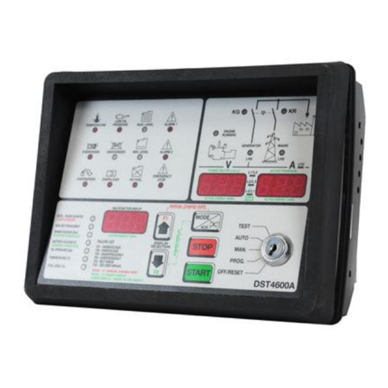
- Page 6 DST4600A and DST4600A/P front panels. User’s Manual...
- Page 7 There are two slightly different front panels. The DST4600A front panel is the standard one. The DST4600A/P front panel is used mainly for switchboard for parallel application; the boards with the DST4600A/P panel have different part number.
- Page 8 status and measurements” area mirror such conditions. By switching the selector to “OFF/RESET” the following operations are executed: 1) Activation of the engine shutdown sequence 2) Forced control of mains power supply 3) Reset of any stored fault causing the generator set shutdown When the board is in the “OFF/RESET”...
- Page 9 5 seconds. There is another hour counter. It cannot be cleared in any way. Its value is not shown on the DST4600A front panel, but can be read by the serial port. ...
- Page 10 “OIL PRESSURE (bar)”: when this function is selected, the display “MULTIFUNCTION” shows the engine’s oil pressure measured on the analogue sensor (terminal 42) (in Bars with a decimal). If the sensor isn’t configured (P47=0), the display will show three dashes (“---“).
- Page 11 In this area (right top of the front panel) is displayed the status of the generator set and of the mains. The following signals are provided: Indicators “KG” and “KR” (green): indicate the status of the contactors managing the power changeover.
- Page 12 phase systems) Volts. The right one (called display “A”) shows the phase currents in Amperes. The view format changes according to the set TA ratio (P17): P17 < 10: the currents are displayed with two decimals P17 >=10 and <100: the currents are displayed with one decimal ...
- Page 13 Indicator “DISCHARGED” (yellow) it indicates the alarm status due to the charge level of the starting battery of the generator set. Such battery also powers the board DST4600A. The alarm is produced if the battery voltage exceeds the tolerance limits: ...
- Page 14 As soon as the board is powered it executes the following operations: Lamp Test: during this phase it turns on all the indicators in the front panel and it shows 888 (with the decimal points turned on) on the three displays. This operation lasts two seconds and allows the identification of any failure in the front panel that could involve visual signaling of a fault.
- Page 15 (if still active) is disabled. Once the operator has recognized the alarms, they are automatically cancelled by DST4600A when the corresponding cause ceases to exist. If the alarm is cancelled, the visual signal turns off, too.
- Page 16 Disabling Bit 2 of Parameter P39 = 0 Conditions to activate it Engine running from the time set through the parameter P31 Digital input “OIL WARNING” (terminal 08) shorted to ground Fuel solenoid activated. Not existent in asynchronous engine version Filter time 2 seconds Quick flashing of the indicator “LOW OIL PRESSURE”...
- Page 17 Disabling Bit 7 of the Parameter P49 = 0 Starting not in progress (output “START”, terminal 20 not Conditions for its activation enabled) Battery voltage under 11.8 (or 23.2) V or battery voltage over 15 (or 30) V Filter time 40 seconds Slow flashing of the indicator “DISCHARGED”...
- Page 18 Disabling Bit 4 of the Parameter P49 = 0 Digital “INPUT B” (terminal 13) shorted to ground Conditions for its activation Filter time Time set through the parameter P40 Message “F10” on the display “MULTIFUNCTION” Visual signal Disabling P75 = 0 Conditions for its AUTO o TEST mode.
- Page 19 Disabling Parameter P13 = 0 Conditions for its No deactivation activation No block Engine running Generator already in the operating window from starting. Shutdown cycle not in progress Fuel solenoid activated With selector on MAN, generator set contactor closed Generator’s voltage under the threshold set through the parameter P13 at least on one phase Not existent in asynchronous engine version Filter time...
- Page 20 Disabling Cannot be disabled Conditions for its Key selector on AUTO or TEST activation STOP button pressed o external STOP command Filter time 0 seconds (immediate) Message “F07” on the display “MULTIFUNCTION” Visual signal Disabling Bit 5 of the Parameter P39 = 0 “FUEL END”...
- Page 21 Disabling Bit 1 Parameter P39 = 0 Conditions for its No block activation Fuel solenoid closed (“FUEL SOLENOID output, terminal 22 enabled) “TEMPERAT. ALARM” digital input (terminal 09) shorted to ground Filter time 2 seconds Indicator “TEMPERATURE” slowly flashing Visual signal Disabling Parameter P46 = 0 and/or parameter P35 = 0 Conditions for its...
- Page 22 Disabling Parameter P14 = max No block Conditions for its Engine Running activation Fuel solenoid activated Generator’s voltage over the threshold set through the parameter P14 at least on one phase Not existent in asynchronous engine version. Filter time Time set through the parameter P24 Message “F02”...
- Page 23 Disabling Bit 2 of the Parameter P49 = 0 Conditions for its No block activation “OVERLOAD” digital input (terminal 11) shorted to ground Filter time Time set through the parameter P40. Starting from 08.00.23 version, a fixed time of 1.5 second is added to the set value. “OVERLOAD”...
- Page 24 Disabling Bit 7 of the Parameter P39 = 0 Conditions for its No block activation Engine running Shutdown cycle not in progress Voltage measured at the D+WL input (terminals 39-40) under the threshold of 8 (or 16) V. Filter time 20 seconds Message “F05”...
- Page 25 Disabling From revision 00.00.40 by setting bit 4 of P79 to 0 Conditions for its Shutdown cycle in progress activation Engine still running after the time limit set through the parameter P09 Filter time Immediate Message “F21” on the display “MULTIFUNCTION” Visual signal Disabling Parameter P52 = 0 and/or Parameter P53 = 0...
- Page 26 Parameters for the mains management: P01: intervention threshold for minimum mains voltage (V) P02: Hysteresis (%) P04: generator set intervention delay for mains voltage failure (s) P05: Mains restoration delay (closing mains contactor from mains present) (s) ...
- Page 27 The T1 and T2 times change according to the position of the key selector and if the engine is running or dead: SELECTOR ENGINE AUTO-TEST Dead MAN-PROG-OFF Dead AUTO-TEST Running (operating speed) 2 s Running (operating speed) 2 s As you can see, the transitional mains failure is cancelled (2 seconds) with the engine running. In such conditions, as soon as a mains failure occurs, if the selector is on AUTO the users are switched on the generator.
- Page 28 4 of the parameter P39. On the DST4600A board this time act only if the generator set contactor is open. If it is closed, wait until the alarms management starts the F01.F04 alarm and then execute the emergency stop cycle.
- Page 29 It is a series of many conditions. The most important one is the absence of any block or deactivation. The remaining conditions depend on the key selector status: a) “START” button pressed. AUTO a) Mains status “Absent” (and no “MAINS SIMULATION”) b) “REMOTE TEST”...
- Page 30 In the MANUAL mode the board DST4600A can receive the engine start/shutdown commands and those for the power changeover from the buttons located on the front panel. When the selector is brought to MANUAL the following operations are executed: ...
- Page 31 Normally, with the board in the MANUAL mode the users are switched on the mains. Only if the engine is running, if the generator is “present” and the delay before the supply has passed - P06 (or if the temperature exceeds the minimum threshold set with P55), the operator has the opportunity to switch them on the generator.
- Page 32 4. The “START” output (terminal 20) controlling the generator set starter, is enabled. The output is kept for the time set with the parameter P08 or until the engine running recognition. In this phase the display “MULTIFUNCTION” shows the message “STA”. If the engine gets started phase 6 will follow, otherwise phase 5 will follow (unless the starting attempts have ended, 5.
- Page 33 The boards waits until the mains gets “present” and all the other start requests get off (see par.5.1.1). Further, the arising of new faults of the generator set is checked. In sequential order there are: Opening of the generator set contactor (closed contact at terminals 58-59) ...
- Page 34 The board is able to execute the true r.m.s measurements on the generator’ voltages and currents as well as the active, reactive, apparent power and power factor measurements of the system when it is powered by the generator. In addition, it manages an energy meter for the power supplied by the generator set.
- Page 35 The energy meter managed by DST4600A counts the energy supplied by the generator set. It has an internal resolution under 100 Wh but it is displayed in kWh. It is updated every second.
- Page 36 Starting from 08.00.24 version, it is possible to avoid black-out due to KR failure. In case of such failure the user power line remains unsupplied if the grid is present. Using this function is possible to guarantee power availability at user level. To use this function the system must be configured as following: ...
- Page 37 You can set the board to control a fuel pump for the automatic filling of the tank. The function can be used only if the fuel level analogue sensor exists. You have to set the two operating threshold: P29: fuel level threshold under which the pump is started. ...
- Page 38 From the software release 08.00.25 is it possible to order as option the second serial port of DST4600A board. It is then possible to connect to this serial port one expansion board provided with 32 digital outputs or 16 outputs and 16 inputs. The outputs can be used as additional remote signals.
- Page 39 “OUTPUT 1” output and the “F49” warning are deactivated (the “F49” warning is still present on the DST4600A panel if not acknowledged). If the active power is between the P56 and P58 thresholds, the maximum power status and the “OUTPUT 1”...
- Page 40 P56. Starting from SW revision 08.00.24, it is possible to install in DST4600A boards a Real Time Clock option (RTC). The option is equipped by a lithium battery that let the watch running also without supply.
- Page 41 Once in RTC display mode (see previous paragraph), pressing “MODE/ACK” the RTC setting mode is entered. Display “F” will show one of the following messages, while display “A” will show the proper value: “SEC”: seconds (valid value 0 through 59) ...
- Page 42 The parameter P19 determines the duration of the test operation of the generator set. If during the programming you change the value P18 the period count will restart from zero in the moment in which you’ll exit the PROGRAMMING procedure. The automatic periodical test is disabled if at least one of the two parameters is equal to zero or if RTC based periodical test is enabled.
- Page 43 The correspondent SW version for the DST4600A/P is 12.05.22. The input function is specialized for the parallel fault condition. The only difference between DST4600A and DST4600A/P is the default of the P65 (ALARM2 (terminal 02) filter time): for DST4600A/P is 180s instead of 1s.
- Page 44 In the standard version, this terminal acquires the high water temperature alarm. In this version, it acquires the “engine in threshold” status, and so the high water temperature alarm is disabled. Only for this version, the board can activate a block (“F40”) when the KG is closed and the signal on terminal 10 becomes inactive, with a fixed filter delay of 0.5 seconds.
- Page 45 This document is owned by SICES s.r.l.. All rights reserved. SICES s.r.l. reserves the right to modify this document without prior notice. SICES has made any effort to ensure that the information herein provide are correct; in any case SICES does not assume any liability for the use these information.
Need help?
Do you have a question about the DST4600A and is the answer not in the manual?
Questions and answers