Sign In
Upload
Manuals
Brands
Sices Manuals
Controller
GC250
User Manuals: Sices GC250 Genset Controller
Manuals and User Guides for Sices GC250 Genset Controller. We have
2
Sices GC250 Genset Controller manuals available for free PDF download: Technical Manual, User Manual
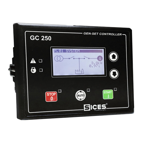
Sices GC250 Technical Manual (145 pages)
Brand:
Sices
| Category:
Controller
| Size: 1 MB
Table of Contents
Table of Contents
3
Sommario
12
Introduction
12
References
12
Information on Safety
12
Introduction and Prerequisites
13
Notes on the Parameters Configuration of the Device
13
Definitions
13
Conventions
14
Software Revisions
14
Views of the Device
15
Technical Features
16
Measurement Resolution
18
Installation
19
Mounting
19
Wiring
19
IN/OUT Connections and Configuration
20
Correspondence Input/Output and Their Logic Functions
21
Plant Type
22
Principle Connection Diagram SSB Plant
23
Principle Connection Diagram SPM Plant
24
And T.02 Device Supply
25
Engine Commands Outputs T.03 and T.04
26
START Command for the Engine Starter Motor
26
FUEL SOLENOID Fuel Solenoid Command
26
D+ Energizing and Checking the Operation of the Recharge Alternator
28
D+ Input Used as Analogue Input
29
Static Digital Outputs and Command Loads Switching
29
Load Switching Commands SSB Plants
30
Load Switching Commands SPM Plants
31
Digital Outputs Configuration
32
AND/OR Logics
35
Analogue Inputs
38
T.13, T.14, T.15 - Resistive Analogue Inputs
38
Configuration and Functions of Analogue Inputs
39
Conversion Curves
42
Digital Inputs
43
D+ Input Used as Analogue Input
43
Virtual Digital Inputs
44
Digital Inputs Configuration
44
Measurement of the Mains Neutral
48
Measurement of the Generator Neutral
49
USB Connection
51
CAN-BUS Connections
52
Command and Indications
53
Front Panel GC250
53
Push-Buttons
53
Indicators
53
Multifunctional Display
56
LCD Lighting
56
Contrast Adjustment
56
Mode Navigation
56
Structure of Display Areas
57
Top Status Bar
57
Status Information (S.XX)
58
Electrical Measures (M.XX)
61
Engine Measurements (E.XX)
64
History Logs (H.XX)
70
Parameters Programming
77
Access to Programming Menu
77
Menu Selection
78
Parameter Organization
78
Parameters Selection
79
Modify a Parameter
79
Set up Limits
80
Exit from Programming
80
Loading Default Values
80
Protection Password
81
Password for Commands from Serial Port (USB)
82
Operation Sequence
83
Operating Mode
83
Recording of Mode in Event Archive
85
Operation Modes and Logics AND/OR
86
Mains
86
Internal Sensor
86
External Mains Sensor
89
Mains Global Status
90
Communication and Events
91
Generator
91
Genset Frequency
91
Genset Voltages
92
Generator Status
93
Communication and Events
94
Automatic Intervention of the Generator Inhibited
94
Inhibition from Contact
94
Inhibition from Clock
95
Engine
95
Engine Running/Stopped Status Acknowledgement
95
Engine Commands
96
Command Sequence of the Engine
97
Communication and Events
100
Circuit Breakers Management
101
Circuit Breakers Command
101
Acquiring Breakers Status
102
OFF/RESET Management Logic
102
Switching Logic in AUTO Mode
102
MAN or TEST Management Logic
103
Automatic Power Delivery of the Generator Inhibited
104
Events and Signallings Related to the Breakers
104
Anomalies
105
Silencing the Horn
106
Acknowledging Anomaly
106
Acknowledging Anomaly
107
Events and Signalling Relative to the Anomalies
107
Anomalies Connected to Digital Inputs
108
Anomalies Connected to Analogue Inputs
109
Anomalies List
109
Minimum Generator Voltage
110
Maximum Generator Voltage
110
Minimum Generator Frequency
110
Maximum Generator Frequency
111
Belt Break (Alternator Battery-Charger Failure)
111
Maximum Current
111
Manual Stop While in AUTO
113
Operating Conditions Failure
113
Mains Circuit Breaker (MCB) Not Closed
114
Genset Circuit Breaker (GCB) Not Closed
114
Short Circuit on the Generator
114
Overspeed
115
Engine Not Stopped
115
Overcrank
115
Mains Circuit Breaker (MCB) Not Open
116
Genset Circuit Breaker (GCB) Not Open
116
Minimum Fuel Level (from Contact)
116
Minimum Fuel Level (from Analogue Sensor)
117
Low Fuel Level (from Contact)
117
Low Fuel Level (from Analogue Sensor)
117
High Fuel Level (from Contact)
118
High Fuel Level (from Analogue Sensor)
118
High Coolant Temperature (from Contact)
118
High Coolant Temperature (from Analogue Sensor)
119
Maximum Coolant Temperature (from Contact)
119
Maximum Coolant Temperature (from Analogue Sensor)
119
Maximum Oil Temperature (from Analogue Sensor)
120
Starter Battery Voltage, Low
120
Starter Battery Voltage, High
120
Service Required
121
Minimum Oil Pressure (from Contact)
121
Minimum Oil Pressure (from Analogue Sensor)
122
Low Oil Pressure (from Contact)
122
Low Oil Pressure (from Analogue Sensor)
122
Emergency Stop
123
Maximum Power
123
Generator Voltages Unbalance
124
Generator Current Unbalance
124
High Oil Temperature (from Analogue Sensor)
124
Wrong Phases Sequence
125
Low Generator Voltage
125
Clock Not Valid
126
Low Generator Frequency
126
High Generator Voltage
126
High Generator Frequency
127
Faulty Engine CAN-BUS 0 Link
127
Fuel Pump Failure
127
Low Coolant Temperature (from Analogue Sensor)
128
Maximum Time Without CAN-BUS Data (Engine)
128
Battery Charger Failure from CAN-BUS
128
Maximum Speed from CAN-BUS
128
High Coolant Temperature from CAN-BUS
129
Maximum Coolant Temperature from CAN-BUS
129
Minimum Coolant Level from CAN-BUS
129
Low Coolant Level from CAN BUS
130
Low Battery Voltage from CAN BUS
130
Minimum Oil Pressure from CAN BUS
130
Low Oil Pressure from CAN BUS
130
High Oil Temperature from CAN BUS
131
Maximum Oil Temperature from CAN BUS
131
Water in Fuel from CAN BUS
131
Warnings Cumulative Yellow Lamp from CAN-BUS
132
Alarms Cumulative Red Lamp from CAN-BUS
132
Other Functions
132
Fuel Pump
132
Use with an Analogue Level Transducer to Use this Function
133
To Use this Function Requires
134
Level Evaluation
134
Automatic Pump Control
134
Manual Pump Control
135
Protections
135
Load Thresholds
135
Low Load
135
High Load
136
Alternative Parameters Configuration
136
EJP Function
137
Maintenance
138
Service Hours Counter
138
Counters
138
Counters Reset
139
Clock
140
Engine TEST Start-Up Weekly Planning
140
Weekly Scheduling of Engine Operating Time Intervals
140
Advertisement
Sices GC250 User Manual (27 pages)
Brand:
Sices
| Category:
Controller
| Size: 1 MB
Table of Contents
Table of Contents
2
Front Panel
5
Buttons
5
Indicators
5
Contrast Adjustment
8
Program
8
Status Information (S.XX)
8
Electrical Measurements (M.XX)
8
Operating Modes
13
Off/Reset
13
Automatic
13
Manual
13
Test
13
Fuel Pump (if Present)
18
Advertisement
Related Products
Sices GC315
Sices GC315Plus
Sices GC400Link
Sices GC400Mains
Sices GC400Mains+Link
Sices GC400
Sices GC310
Sices GC350
Sices GC500
Sices GC500Plus
Sices Categories
Controller
Control Panel
Industrial Equipment
Computer Hardware
Remote Control
More Sices Manuals
Login
Sign In
OR
Sign in with Facebook
Sign in with Google
Upload manual
Upload from disk
Upload from URL